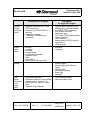
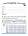
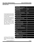
1
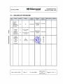
Supplement A31 Garmin G1000, VFR DA 40 D AFM 0.2 LIST OF EFFECTIVE PAGES Chapter Page Date 9-A31-0 08 Sep 2006 9-A31-1 01 Jun 2008 9-A31-2 01 Jun 2008 9-A31-3 01 Jun 2008 % 9-A31-4 01 Jun 2008 % 9-A31-5 01 Jun 2008 9-A31-6 01 Jun 2008 9-A31-7 01 Jun 2008 % 9-A31-8 01 Jun 2008 % 9-A31-9 01 Jun 2008 % 9-A31-10 01 Jun 2008 % 9-A31-11 01 Jun 2008 % 9-A31-12 01 Jun 2008 % 9-A31-13 01 Jun 2008 % 9-A31-14 01 Jun 2008 % 9-A31-15 01 Jun 2008 % 9-A31-16 01 Jun 2008 9-A31-17 01 Jun 2008 % 9-A31-18 01 Jun 2008 % 9-A31-19 01 Jun 2008 % 9-A31-20 01 Jun 2008 % % % % % % 0 1 2 % % % % % % Doc. # 6.01.05-E Rev. 3 01 Jun 2008 OÄM 40-224 or OÄM 40-268 Page 9 - A31 - 2 Supplement A31 Garmin G1000, VFR DA 40 D AFM Chapter Page Date % 9-A31-21 01 Jun 2008 % 9-A31-22 01 Jun 2008 % 9-A31-23 01 Jun 2008 % 9-A31-24 01 Jun 2008 % 9-A31-25 01 Jun 2008 % 9-A31-26 01 Jun 2008 9-A31-27 01 Jun 2008 9-A31-28 01 Jun 2008 % 9-A31-29 01 Jun 2008 % 9-A31-30 01 Jun 2008 % 9-A31-31 01 Jun 2008 % 9-A31-32 01 Jun 2008 % 9-A31-33 01 Jun 2008 % 9-A31-34 01 Jun 2008 % 9-A31-35 01 Jun 2008 9-A31-36 01 Jun 2008 % 9-A31-37 01 Jun 2008 % 9-A31-38 01 Jun 2008 % 9-A31-39 01 Jun 2008 9-A31-40 01 Jun 2008 9-A31-41 01 Jun 2008 % 9-A31-42 01 Jun 2008 % 9-31A-43 01 Jun 2008 9-A31-44 01 Jun 2008 % % % % % % 3 4A 4B 5, 6 % Doc. # 6.01.05-E Rev. 3 01 Jun 2008 OÄM 40-224 or OÄM 40-268 Page 9 - A31 - 3 Supplement A31 Garmin G1000, VFR DA 40 D AFM Chapter Page Date % 9-A31-45 01 Jun 2008 % 9-A31-46 01 Jun 2008 % 9-A31-47 01 Jun 2008 % 9-A31-48 01 Jun 2008 % 9-A31-49 01 Jun 2008 9-A31-50 01 Jun 2008 % 9-A31-51 01 Jun 2008 % 9-A31-52 01 Jun 2008 % 9-A31-53 01 Jun 2008 % 9-A31-54 01 Jun 2008 % 9-A31-55 01 Jun 2008 9-A31-56 01 Jun 2008 % % 7 8 Doc. # 6.01.05-E Rev. 3 01 Jun 2008 OÄM 40-224 or OÄM 40-268 Page 9 - A31 - 4 Supplement A31 Garmin G1000, VFR DA 40 D AFM 0.3 TABLE OF CONTENTS Page 1. GENERAL . . . . . . . . . . . . . . . . . . . . . . . . . . . . . . . . . . . . . . . . . . . . . . . 9-A31-6 2. OPERATING LIMITATIONS . . . . . . . . . . . . . . . . . . . . . . . . . . . . . . . . . . 9-A31-8 % 3. EMERGENCY PROCEDURES . . . . . . . . . . . . . . . . . . . . . . . . . . . . . . 9-A31-21 % 4A. NORMAL OPERATING PROCEDURES . . . . . . . . . . . . . . . . . . . . . . . 9-A31-35 % 4B. ABNORMAL OPERATING PROCEDURES . . . . . . . . . . . . . . . . . . . . . 9-A31-38 % 5. PERFORMANCE . . . . . . . . . . . . . . . . . . . . . . . . . . . . . . . . . . . . . . . . . 9-A31-44 % 6. MASS AND BALANCE . . . . . . . . . . . . . . . . . . . . . . . . . . . . . . . . . . . . . 9-A31-44 % 7. DESCRIPTION OF THE AIRPLANE AND ITS SYSTEMS . . . . . . . . . . 9-A31-45 % 8. AIRPLANE HANDLING, CARE AND MAINTENANCE . . . . . . . . . . . . . 9-A31-56 Doc. # 6.01.05-E Rev. 3 01 Jun 2008 OÄM 40-224 or OÄM 40-268 Page 9 - A31 - 5 Supplement A31 Garmin G1000, VFR DA 40 D AFM 1. GENERAL This Supplement supplies the information necessary for the efficient operation of the airplane when the Integrated Avionics System Garmin, G1000 is installed. The information contained within this Supplement is to be used in conjunction with the complete AFM. This Supplement is a permanent part of this AFM and must remain in this AFM at all times when the G1000 is installed. 1.5 DEFINITIONS AND ABBREVIATIONS (f) Designation of the circuit breakers on the instrument panel ESSENTIAL BUS HORIZON ADC AHRS COM1 FLOOD GPS/NAV1 XPDR LANDING PFD PITOT FLAPS AP WARN MASTER CONTROL ESS TIE ENG INST Doc. # 6.01.05-E Rev. 3 Artificial Horizon (Attitude Gyro) Air Data Computer Attitude and Heading Reference System COM Radio No. 1 Flood Light Global Positioning System and NAV Receiver No. 1 Transponder Landing Light Primary Flight Display Pitot Heating System Flap System Autopilot Warning Master Control (Avionics Relay) Bus Interconnection Engine Instruments 01 Jun 2008 OÄM 40-224 or OÄM 40-268 Page 9 - A31 - 6 Supplement A31 Garmin G1000, VFR DA 40 D AFM MAIN BUS MAIN TIE XFER PUMP MFD INST. LT AV/CDU FAN PWR STROBE POSITION TAXI/MAP START AV. BUS Bus Interconnection Fuel Transfer Pump Multi Function Display Instrument Lights Avionic-, CDU-Cooling Fans Power Strobe Lights (= Anti Collision Lights) Position Lights Taxi Light / Map Lights Starter Avionic Bus ECU BUS ECU ALT. ECU A ECU B ECU Alternate power relay ECU A ECU B AVIONICS BUS GPS/NAV2 COM2 AUDIO AP ADF DME WX500 Doc. # 6.01.05-E Global Positioning System and NAV Receiver No. 2 COM Radio No. 2 Audio Panel / Marker Beacon Receiver Autopilot System Automatic Direction Finder Distance Measuring Equipment Stormscope Rev. 3 01 Jun 2008 OÄM 40-224 or OÄM 40-268 Page 9 - A31 - 7 Supplement A31 Garmin G1000, VFR DA 40 D AFM 2. LIMITATIONS NOTE There is no change in existing operating limitations of the airplane. Following information is exclusively to reflect the indications on the Garmin G1000. % 2.4 POWER-PLANT LIMITATIONS % g) Oil temperature % % % TAE 125-01 TAE 125-02-99 (MÄM 40-256 carried out) % Minimum -32 °C -30 °C % Maximum +140 °C +140 °C TAE 125-01 TAE 125-02-99 (MÄM 40-256 carried out) % i) Coolant temperature % % % % Minimum -32 °C -30 °C % Maximum +105 °C +105 °C Doc. # 6.01.05-E Rev. 3 01 Jun 2008 OÄM 40-224 or OÄM 40-268 Page 9 - A31 - 8 Supplement A31 Garmin G1000, VFR DA 40 D AFM 2.5 ENGINE INSTRUMENT MARKINGS % Engine instrument markings and their color code significance are shown in the tables below: % If the TAE 125-01 engine is installed: Indication Red arc/bar = lower prohibited range Yellow arc/bar = caution range Green arc/bar = normal operating range Yellow arc/bar = caution range Red arc/bar = upper prohibited range -- -- up to 2400 RPM 2400 to 2500 RPM above 2500 RPM Oil pressure below 1.2 bar 1.2 to 2.3 bar 2.3 to 5.2 bar 5.2 to 6.5 bar above 6.5 bar Oil temp. below -32 °C -32 to 50 °C 50 to 130 °C 130 to 140 °C above 140 °C Coolant temp. below -32 °C -32 to 60 °C 60 to 101 °C 101 to 105 °C above 105 °C Gearbox temp. -- -- up to 115 °C 115 to 120 °C above 120 °C Load -- -- 0 - 100 % -- -- Fuel temp. below -30 °C -30 to 5 °C 5 to 70 °C 70 to 75 °C above 75 °C -- -- up to 85 A 85 to 90 A above 90 A below 11 V 11 to 12.6 V 12.6 to 15.0 V 15.0 to 15.5 V above 15.5 V -- -- RPM Ammeter Voltmeter Fuel qty. below 0.45 US gal Doc. # 6.01.05-E -- Rev. 3 0.45 to 14 US gal 01 Jun 2008 OÄM 40-224 or OÄM 40-268 Page 9 - A31 - 9 Supplement A31 Garmin G1000, VFR DA 40 D AFM % If the TAE 125-02-99 engine is installed (MÄM 40-256 is carried out): % % % % % % Indication Red arc/bar = lower prohibited range Yellow arc/bar = caution range Green arc/bar = normal operating range Yellow arc/bar = caution range Red arc/bar = upper prohibited range -- -- 0-2300 RPM -- above 2300 RPM % % % RPM % % % Oil pressure below 1.2 bar 1.2 to 2.3 bar 2.3 to 5.8 bar 5.8 to 6.5 bar above 6.5 bar % % % Oil temp. below -30 °C -30 to 50 °C 50 to 130 °C 130 to 140 °C above 140 °C % % % Coolant temp. below -30 °C -30 to 60 °C 60 to 101 °C 101 to 105 °C above 105 °C % % % Gearbox temp. -- -- up to 115 °C 115 to 120 °C above 120 °C % Load -- -- 0 - 100 % -- -- % % % Fuel temp. below -30 °C -30 to +5 °C +5 to 70 °C 70 to 75 °C above 75 °C % % % Ammeter -- -- up to 85 A 85 to 90 A above 90 A % % % Voltmeter below 11 V 11 to 12.6 V 12.6 to 15.0 V 15.0 to 15.5 V above 15.5 V % % % Fuel qty. below -- 1 to 14 US gal -- -- 1 US gal Doc. # 6.01.05-E Rev. 3 01 Jun 2008 OÄM 40-224 or OÄM 40-268 Page 9 - A31 - 10 Supplement A31 Garmin G1000, VFR DA 40 D AFM 2.6 WARNING, CAUTION AND STATUS LIGHTS NOTE Airplanes equipped with the Garmin G1000 have no annunciation panel. All annunciations are displayed on the G1000. The annunciations differ from those listed in the main part of the AFM. The following tables show the color and significance of the warning, caution and advisory alerts lights on the G1000. Color and significance of the warning alerts on the G1000 Warning alerts Meaning / Cause (red) WARNING ENG TEMP OIL TEMP OIL PRES L/R FUEL TEMP One of the Warnings listed below is being indicated. Engine coolant temperature is in the upper red range (too high / > 105 °C). Engine oil temperature is in the upper red range (too high / >140 °C). Engine oil pressure is in the lower red range (too low / < 1.2 bar). Fuel temperature is in the upper red range (too high / > 75 °C) GBOX TEMP Engine gearbox temperature is in the upper red range (too high / > 120 °C). ALTN AMPS Engine alternator output is in the upper red range (too high / > 90 amps). Doc. # 6.01.05-E Rev. 3 01 Jun 2008 OÄM 40-224 or OÄM 40-268 Page 9 - A31 - 11 Supplement A31 Garmin G1000, VFR DA 40 D AFM Warning alerts Meaning / Cause (red) ALTN FAIL Engine alternator has failed. STARTER Engine starter is engaged. DOOR OPEN Front and/or rear canopy are/is not closed and locked. AP TRIM FAIL Failure in the automatic trim system of the autopilot (if autopilot installed). POSN ERROR G1000 will no longer provide GPS based navigational guidance. ATTITUDE FAIL The display system is not receiving attitude reference information from the AHRS. AIRSPEED FAIL The display system is not receiving airspeed input from the air data computer. ALTITUDE FAIL The display system is not receiving altitude input from the air data computer. VERT SPEED FAIL The display system is not receiving vertical speed input from the air data computer. HDG The display system is not receiving valid heading input from the AHRS. WARN RAIM position warning. The nav deviation bar is removed. Doc. # 6.01.05-E Rev. 3 01 Jun 2008 OÄM 40-224 or OÄM 40-268 Page 9 - A31 - 12 Supplement A31 Garmin G1000, VFR DA 40 D AFM Color and significance of the caution alerts on the G1000 Meaning / Cause Caution-alerts (yellow) CAUTION One of the Cautions below is being indicated. * ECU A FAIL ECU B FAIL Engine ECU A has failed or * is tested during FADEC-test procedure during before takeoff check. * Engine ECU B has failed or * is tested during FADEC-test procedure during before takeoff check. L FUEL LOW Main tank fuel quantity is low. VOLTS LOW Engine bus voltage is too low (< 12.6 volts). COOL LVL Engine coolant level is low. PITOT FAIL Pitot heat has failed. PITOT HT OFF Pitot heat is OFF. INTEG RAIM not available RAIM (Receiver Autonomous Integrity Monitor) is not available. AHRS ALIGN: Keep Wings Level The AHRS (Attitude and Heading Reference System) is aligning. Doc. # 6.01.05-E Rev. 3 01 Jun 2008 OÄM 40-224 or OÄM 40-268 Page 9 - A31 - 13 Supplement A31 Garmin G1000, VFR DA 40 D AFM Color and significance of the advisory alerts on the G1000 Meaning / Cause advisory alerts (white) GLOW ON Engine glow plug active. FUEL XFER Fuel transfer from auxiliary to main tank is in progress. PFD FAN FAIL Cooling fan for the PFD is inoperative. MFD FAN FAIL Cooling fan for the PFD is inoperative. GIA FAN FAIL Cooling fan for the GIAs is inoperative. Doc. # 6.01.05-E Rev. 3 01 Jun 2008 OÄM 40-224 or OÄM 40-268 Page 9 - A31 - 14 Supplement A31 Garmin G1000, VFR DA 40 D AFM 2.13 KINDS OF OPERATION Provided that national operational requirements are met, the following kinds of operation are approved: • • daytime flights according to Visual Flight Rules (VFR) with the appropriate equipment: night flights according to Visual Flight Rules (VFR) Flights into known or forecast icing conditions are prohibited. Flights into known thunderstorms are prohibited. Minimum operational equipment (serviceable) The following table lists the minimum serviceable equipment required by JAR-23. Additional minimum equipment for the intended operation may be required by national operating rules and also depends on the route to be flown. NOTE Many of the items of minimum equipment listed in the following table are integrated in the G1000. Doc. # 6.01.05-E Rev. 3 01 Jun 2008 OÄM 40-224 or OÄM 40-268 Page 9 - A31 - 15 Supplement A31 Garmin G1000, VFR DA 40 D AFM for daytime VFR flights in addition for night VFR flights Flight & navigation instruments • airspeed indicator (on G1000 PFD or backup) • altimeter (on G1000 PFD or backup) • magnetic compass • 1 headset, used by pilot in command • vertical speed indicator (VSI) • attitude gyro (artificial horizon; on G1000 PFD or backup) • turn & bank indicator • directional gyro • VHF radio (COM) with speaker and microphone • VOR receiver • transponder (XPDR), mode A and mode C • GPS receiver engine instruments • • • • • • • • • • ammeter • voltmeter fuel qty. oil press. oil temp. coolant temp. coolant level indicator gearbox temp. load prop. RPM fuel temp. left & right tank lighting other operational minimum equipment • position lights • strobe lights (anti collision lights) • landing light • instrument lighting • flood light • flashlight • stall warning system • Pitot heating system • alternate means for fuel quantity • alternate static valve indication (see Section 7.9) • safety belts for each occupied seat • Airplane Flight Manual Doc. # 6.01.05-E Rev. 3 01 Jun 2008 OÄM 40-224 or OÄM 40-268 Page 9 - A31 - 16 Supplement A31 Garmin G1000, VFR DA 40 D AFM 2.16.8 GARMIN G1000 AVIONICS SYSTEM 1. The Garmin G1000 Cockpit Reference Guide, P/N 190-00324-03 Rev. A or later appropriate revision must be immediately available to the flight Crew. 2. The G1000 must utilize the software Garmin P/N: 010-00370-11, or later approved software in accordance with the mandatory service bulletin DAI MSB D4-045, latest version. Doc. # 6.01.05-E Rev. 3 01 Jun 2008 OÄM 40-224 or OÄM 40-268 Page 9 - A31 - 17 Supplement A31 Garmin G1000, VFR DA 40 D AFM Software Approved Function Version for approved version, see DAI MSB D4-045, latest version System 010-00370-( ) Manifest 006-B0093-( ) 006-B0172-( ) 006-B0190-( ) 006-B0193-( ) 006-B0203-( ) 006-B0223-( ) 006-B0224-( ) 006-B0319-( ) 006-B0328-( ) 006-B0329-( ) 006-C0048-( ) 006-C0049-( ) 006-C0055-( ) 006-D0159-( ) GPS1, GPS2 GTX1-GIA1, GTX1-GIA2 GIA1, GIA2 GEA1-GIA1; GEA1-GIA2 GMA1-GIA1, GMA1-GAI2 GRS1-GIA1, GRS1-GIA2 GMU1 PFD1, MFD1 GMU1 FPGA GRS1 FPGA GDC1 FPGA GRS1 MV DB 006-D0202-( ) 006-B0261-( ) GDC1-GIA1 006-B0081-( ) COM1, COM2 006-B0083-( ) GS1, GS2 006-B0082-( ) NAV1, NAV2 Doc. # 6.01.05-E Rev. 3 01 Jun 2008 OÄM 40-224 or OÄM 40-268 Page 9 - A31 - 18 Supplement A31 Garmin G1000, VFR DA 40 D AFM NOTE The database version is displayed on the MFD power-up page immediately after system power-up and must be acknowledged. The remaining system software versions can be verified on the AUX group sub-page 5, "AUX SYSTEM STATUS". 3. If not previously defined, the following default settings must be made in the "SYSTEM SETUP" menu of the G1000 prior to operation (refer to Pilot's Guide for procedure if necessary): (a) DIS, SPD : nm, kt (sets navigation units to "nautical miles" and "knots") (b) ALT, VS : ft, fpm (sets altitude units to "feet" and "feet per minute") (c) MAP DATUM : WGS 84 (sets map datum to WGS-84, see note below) (d) POSITION : deg-min (sets navigation grid units to decimal minutes) NOTE In some areas, datums other than WGS-84 or NAD-83 may be used. If the G1000 is authorized for use by the appropriate Airworthiness Authority, the required geodetic datum must be set in the G1000 prior to its use for navigation. 4. Operation is prohibited north of 70° N and south of 70° S latitudes. In addition, operation is prohibited in the following two regions: (a) north of 65° N between 75° W and 120° W longitude, and (b) south of 55° S between 120° E and 165° E longitude. Doc. # 6.01.05-E Rev. 3 01 Jun 2008 OÄM 40-224 or OÄM 40-268 Page 9 - A31 - 19 Supplement A31 Garmin G1000, VFR DA 40 D AFM 5. The fuel quantity, fuel required, and fuel remaining functions on the Fuel Page (displayed when pushing the FUEL button as shown in Section 7.9.4) of the FMS are supplemental information only and must be verified by the flight crew. 6. The pilot's altimeter is the primary altitude reference during all operations using advisory vertical navigation (VNAV) information. 7. Navigation must not be predicated upon the use of the Terrain or Obstacle data displayed by the G1000. NOTE The terrain display is intended to serve as a situational awareness tool only. It may not provide either the accuracy or fidelity, or both, on which to solely base decisions and plan maneuvers to avoid terrain ir obstacles. 8. The Terrain/Obstacle/Airport databases have an area of coverage as detailed below: 1. The Terrain Database has an area of coverage from North 75° Latitude to South 60° Latitude in all longitudes. 2. The Airport Terrain Database has an area of coverage that includes the United States, Canada, Mexico, Latin America, and South America. 3. The Obstacle Database has an area of coverage that includes the United States. Doc. # 6.01.05-E Rev. 3 01 Jun 2008 OÄM 40-224 or OÄM 40-268 Page 9 - A31 - 20 Supplement A31 Garmin G1000, VFR DA 40 D AFM 3. EMERGENCY PROCEDURES 3.1.3 SELECTING EMERGENCY FREQUENCY In an in-flight emergency, depressing and holding the Com transfer button »º on the G1000 for 2 seconds will tune the emergency frequency of 121.500 MHz. If the display is available, it will also show it in the "Active" frequency window. 3.8 AIRPLANE RELATED G1000 WARNINGS NOTE Airplanes equipped with the Garmin G1000 have no annunciation panel. All annunciations are displayed on the G1000. The annunciations differ from those listed in the main part of the AFM. 3.8.1 WARNINGS / GENERAL CHARACTERISTICS Means that the non-observation of the corresponding procedure leads to an immediate or important degradation in flight-safety. Red color coded warning text. Warning chime tone of 1.5 second duration which repeats without delay until acknowledged by the crew. Doc. # 6.01.05-E Rev. 3 01 Jun 2008 OÄM 40-224 or OÄM 40-268 Page 9 - A31 - 21 Supplement A31 Garmin G1000, VFR DA 40 D AFM 3.8.2 ENG TEMP Engine coolant temperature is in the upper red range (too high / above 105 °C) ENG TEMP - Check coolant qty. caution (COOL LVL). if off: during climb: - Reduce power by 10 %. - Increase airspeed by 10 KIAS. - If the coolant temperature does not reach the green range within 60 seconds, reduce power as far as possible and increase airspeed. during cruise: - Reduce power. - Increase airspeed. - Check coolant temperature in green range. CAUTION If the coolant temperature does not return to the green range, perform a precautionary landing on the nearest airfield in accordance with the procedures given in the AFM. if on: - Reduce power. - Expect loss of coolant. Doc. # 6.01.05-E Rev. 3 01 Jun 2008 OÄM 40-224 or OÄM 40-268 Page 9 - A31 - 22 Supplement A31 Garmin G1000, VFR DA 40 D AFM WARNING A further increase in coolant temperature must be expected. Prepare for an emergency landing in accordance with the procedures given in the AFM. 3.8.3 OIL TEMP OIL TEMP - Engine oil temperature is in the upper red range (too high / above 140 °C). Check oil pressure. if the oil pressure is low: - Reduce power. - Expect loss of oil with engine failure. Prepare for an emergency landing in accordance with the procedures given in the AFM. if the oil pressure is within the green range: - Reduce power. - Increase airspeed. Doc. # 6.01.05-E Rev. 3 01 Jun 2008 OÄM 40-224 or OÄM 40-268 Page 9 - A31 - 23 Supplement A31 Garmin G1000, VFR DA 40 D AFM 3.8.4 OIL PRES Engine oil pressure is in the lower red range (too low / below 1.2 bar). OIL PRES NOTE If the RPM indication is less than 1500 RPM with the power lever at IDLE, the oil pressure must drop into the red range to cause the OIL PRES warning to illuminate. - Reduce power. Expect loss of oil with engine failure. Prepare for an emergency landing in accordance with the procedures given in the AFM. 3.8.5 GBOX TEMP GBOX TEMP - Reduce power. - Increase airspeed. Engine gearbox temperature is in the upper red range (too high / above 120 °C). 3.8.6 L/R FUEL TEMP L/R FUEL TEMP - Reduce power. - Increase airspeed. Doc. # 6.01.05-E Fuel temperature is in the upper red range (too high / above 75 °C). Rev. 3 01 Jun 2008 OÄM 40-224 or OÄM 40-268 Page 9 - A31 - 24 Supplement A31 Garmin G1000, VFR DA 40 D AFM 3.8.7 ALTN AMPS ALTN AMPS Engine alternator output is in the upper red range (too high / above 90 amps). This warning is indicated when the consumption of electrical power is too high. Possible reasons are: - A fault in wiring or equipment 1. Electrical equipment . . . . . . . . . . . . . . . . . . . switch OFF as necessary and possible to reduce electric load if the problem does not clear itself: 2. Land on the nearest suitable airfield. Doc. # 6.01.05-E Rev. 3 01 Jun 2008 OÄM 40-224 or OÄM 40-268 Page 9 - A31 - 25 Supplement A31 Garmin G1000, VFR DA 40 D AFM 3.8.8 ALTN FAIL Engine alternator has failed. ALTN FAIL An alternator failure is indicated by a warning light (ALTN FAIL) on the G1000 System. The batteries are the last remaining source of electrical power for about 30 minutes. 1. Circuit breakers . . . . . . . . . . . . . . . . . . . . . . check; if all are O.K., proceed with step 2 2. ESSENTIAL BUS . . . . . . . . . . . . . . . . . . . . . ON 3. Electrical equipment . . . . . . . . . . . . . . . . . . . switch OFF all equipment which is not needed 4. Land on the nearest suitable airfield WARNING The ECU which is absolutely necessary for engine operation needs electrical power. It is recommended to switch off all electrical consumers and to land as soon as possible. Be prepared for an engine failure and an emergency landing. For a severe electrical failure a ECUBackup-System is installed. Doc. # 6.01.05-E Rev. 3 01 Jun 2008 OÄM 40-224 or OÄM 40-268 Page 9 - A31 - 26 Supplement A31 Garmin G1000, VFR DA 40 D AFM 3.8.9 STARTER STARTER Engine starter is engaged A 'STARTER'-warning on the G1000 System is equivalent to a 'START'-warning indicated on the annunciator panel as described in the AFM and all its procedures, whereby the 'STARTER'-warning of the G1000 is steady-on when appearing. 3.8.10 DOOR OPEN DOOR OPEN Front and/or rear canopy door are/is not closed and locked. A 'DOOR OPEN'-warning on the G1000 System is equivalent to a 'DOOR'-warning indicated on the annunciator panel as described in the AFM and in all its procedures. Doc. # 6.01.05-E Rev. 3 01 Jun 2008 OÄM 40-224 or OÄM 40-268 Page 9 - A31 - 27 Supplement A31 Garmin G1000, VFR DA 40 D AFM 3.9 G1000 SYSTEM WARNINGS 3.9.1 RED X A red X through any display field, such as COM frequencies, NAV frequencies, or engine data, indicates that display field is not receiving valid data. 3.9.2 POSN ERROR POSN ERROR The system will flag and no longer provide GPS based navigational guidance. Revert to the G1000 VOR/ILS receivers or an alternate means of navigation other than the G1000 GPS receivers. 3.9.3 ATTITUDE FAIL ATTITUDE FAIL The display system is not receiving attitude reference information from the AHRS; accompanied by the removal of sky/ground presentation and a red X over the attitude area. Revert to the standby attitude indicator. Doc. # 6.01.05-E Rev. 3 01 Jun 2008 OÄM 40-224 or OÄM 40-268 Page 9 - A31 - 28 Supplement A31 Garmin G1000, VFR DA 40 D AFM 3.9.4 AIRSPEED FAIL The display system is not receiving airspeed input from the air data computer; accompanied by a red X through the airspeed display. AIRSPEED FAIL Revert to the standby airspeed indicator. 3.9.5 ALTITUDE FAIL The display system is not receiving altitude input from the air data computer; accompanied by a red X through the altimeter display. ALTITUDE FAIL Revert to the standby altimeter. 3.9.6 VERT SPEED FAIL VERT SPEED FAIL The display system is not receiving vertical speed input from the air data computer; accompanied by a red X through the vertical speed display. Determine vertical speed based on the change of altitude information. Doc. # 6.01.05-E Rev. 3 01 Jun 2008 OÄM 40-224 or OÄM 40-268 Page 9 - A31 - 29 Supplement A31 Garmin G1000, VFR DA 40 D AFM 3.9.7 HDG HDG The display system is not receiving valid heading input from the AHRS; accompanied by a red X through the digital heading display. Revert to the emergency compass. 3.9.8 WARN WARN RAIM position warning - nav deviation bar removed. 1. CDI softkey . . . . . . . . . . . . . . . . . . . . . . . . . . switch to VOR/LOC Doc. # 6.01.05-E Rev. 3 01 Jun 2008 OÄM 40-224 or OÄM 40-268 Page 9 - A31 - 30 Supplement A31 Garmin G1000, VFR DA 40 D AFM 3.10 G1000 FAILURES 3.10.1 NAVIGATION INFORMATION FAILURE If GARMIN G1000 GPS navigation information is not available or invalid, utilize remaining operational navigation equipment as required. 3.10.2 PFD OR MFD DISPLAY FAILURE 1. DISPLAY BACKUP button on audio panel . . PUSH % Automatic Entry of Display Revisionary Mode % If the PFD and MFD have automatically entered reversionary mode, use the following % procedure. % (a) DISPLAY BACKUP button on audio panel ... PUSH (button will be OUT) % NOTE % After automatic entry of reversionary mode, the pilot must % press the DISPLAY BACKUP button on the audio panel. % After the DISPLAY BACKUP button has been pushed, the % system will remain in reversionary mode even if the % problem causing the automatic entry of reversionary mode % is resolved. A maximum of one attempt to return to normal % mode is approved using the following procedure. % (b) DISPLAY BACKUP button on audio panel ...... PUSH (button will be IN) % - If the system returns to normal mode, leave the DISPLAY BACKUP button IN and % continue. % - lf the system remains in reversionary mode, or abnormal display behavior such % as display flashing occurs, then return the DISPLAY BACKUP button to the OUT % position. Doc. # 6.01.05-E Rev. 3 01 Jun 2008 OÄM 40-224 or OÄM 40-268 Page 9 - A31 - 31 Supplement A31 Garmin G1000, VFR DA 40 D AFM 3.10.3 AHRS FAILURE NOTE A failure of the Attitude and Heading Reference System (AHRS) is indicated by a removal of the sky/ground presentation and a red X and a yellow "AHRS FAILURE" shown on the PFD. The digital heading presentation will be replaced with a yellow "HDG" and the compass rose digits will be removed. The course pointer will indicate straight up and course may be set using the digital window. 1. Use standby attitude indicator, emergency compass and Navigation Map 2. Course . . . . . . . . . . . . . . . . . . . . . . . . . . . . . set using digital window 3.10.4 AIR DATA COMPUTER (ADC) FAILURE NOTE Complete loss of the Air Data Computer is indicated by a red X and yellow text over the airspeed, altimeter, vertical speed, TAS and OAT displays. Some FMS functions, such as true airspeed and wind calculations, will also be lost. 1. Use standby airspeed indicator and altimeter. Doc. # 6.01.05-E Rev. 3 01 Jun 2008 OÄM 40-224 or OÄM 40-268 Page 9 - A31 - 32 Supplement A31 Garmin G1000, VFR DA 40 D AFM 3.10.5 ERRONEOUS OR LOSS OF ENGINE AND FUEL DISPLAYS NOTE Loss of an engine parameter is indicated by a red X through the data field. Erroneous information may be identified by indications which do not agree with other system information. Erroneous indications may be determined by comparing a display with other displays and other system information. 1. Set power based on throttle lever position, engine noise and speed. 2. Monitor other indications to determine the health of the engine. 3. Use known power settings and performance data of the AFM for approximate fuel flow values. 4. Use other system information, such as annunciator messages, GPS fuel quantity and flow, to safely complete the flight. Doc. # 6.01.05-E Rev. 3 01 Jun 2008 OÄM 40-224 or OÄM 40-268 Page 9 - A31 - 33 Supplement A31 Garmin G1000, VFR DA 40 D AFM 3.10.6 ERRONEOUS OR LOSS OF WARNING/CAUTION ANNUNCIATORS NOTE Loss of an annunciator may be indicated when engine or fuel displays show an abnormal or emergency situation and the annunciator is not present. An erroneous annunciator may be identified when an annunciator appears which does not agree with other displays or system information. 1. If an annunciator appears, treat it as if the condition exists. Refer to the procedures given in the AFM. 2. If a display indicates an abnormal condition but no annunciator is present, use other system information, such as engine displays, GPS fuel quantity and flow, to determine if the condition exists. If it cannot be determined that the condition does not exist, treat the situation as if the condition exists. Refer to the procedures given in the AFM. Doc. # 6.01.05-E Rev. 3 01 Jun 2008 OÄM 40-224 or OÄM 40-268 Page 9 - A31 - 34 Supplement A31 Garmin G1000, VFR DA 40 D AFM 4A. NORMAL OPERATING PROCEDURES NOTE Airplanes equipped with the Garmin G1000 have no annunciation panel. All annunciations are displayed on the G1000. The annunciations differ from those listed in the main part of the AFM. 4A.3.4 BEFORE TAXIING WARNING Do not load a new departure procedure in the flight plan of the G 1000 if one currently exists without first removing the existing departure procedure. Failing to observe this limitation can cause erroneous course deviation indications, loss of GPS navigation information and other display anomalies. NOTE If display anomalies are noted after editing the flight plan on the G 1000, perform either a direct to or activate leg operation as appropriate on the flight plan to ensure correct flight plan sequencing and guidance. Doc. # 6.01.05-E Rev. 3 01 Jun 2008 OÄM 40-224 or OÄM 40-268 Page 9 - A31 - 35 Supplement A31 Garmin G1000, VFR DA 40 D AFM 4A.3.11 DESCENT WARNING Do not load a new arrival procedure in the flight plan of the G 1000 if one currently exists without first removing the existing arrival procedure. Failing to observe this limitation can cause erroneous course deviation indications, loss of GPS navigation information and other display anomalies. NOTE If display anomalies are noted after editing the flight plan on the G 1000, perform either a direct to or activate leg operation as appropriate on the flight plan to ensure correct flight plan sequencing and guidance. Doc. # 6.01.05-E Rev. 3 01 Jun 2008 OÄM 40-224 or OÄM 40-268 Page 9 - A31 - 36 Supplement A31 Garmin G1000, VFR DA 40 D AFM 4A.4 ADVISORY ALERTS ON THE G1000 The G1000 provides the following advisory-alerts on the PFD in the alert area: 4A.4.1 ADVISORY / GENERAL White color coded text CHARACTERISTICS 4A.4.2 GLOW ON GLOW ON Engine glow plug active 4A.4.3 FUEL XFER FUEL XFER Fuel transfer from auxiliary to main tank is in progress 4A.4.4 PFD/MFD/GIA FAN FAIL PFD FAN FAIL Cooling Fan for the PFD is inoperative MFD FAN FAIL Cooling Fan for the MFD is inoperative GIA FAN FAIL Cooling Fan for the GIA is inoperative The flight may be continued, but maintenance action is required after landing. Doc. # 6.01.05-E Rev. 3 01 Jun 2008 OÄM 40-224 or OÄM 40-268 Page 9 - A31 - 37 Supplement A31 Garmin G1000, VFR DA 40 D AFM 4B. ABNORMAL OPERATING PROCEDURES 4B.8 ENGINE INSTRUMENT INDICATIONS OUTSIDE OF GREEN RANGE ON THE G1000 4B.8.1 HIGH RPM Proceed according to: 4B.2.1 RPM in the main part of the AFM. 4B.8.2 HIGH OR LOW COOLANT TEMPERATURE Proceed according to: 4B.2.2 COOLANT TEMPERATURE CT in the main part of the AFM. 4B.8.3 HIGH OR LOW OIL TEMPERATURE Proceed according to: 4B.2.3 OIL TEMPERATURE OT in the main part of the AFM. 4B.8.4 HIGH OR LOW OIL PRESSURE Proceed according to: 4B.2.4 OIL PRESSURE OP in the main part of the AFM. Doc. # 6.01.05-E Rev. 3 01 Jun 2008 OÄM 40-224 or OÄM 40-268 Page 9 - A31 - 38 Supplement A31 Garmin G1000, VFR DA 40 D AFM 4B.8.5 HIGH GEARBOX TEMPERATURE Proceed according to: 4B.2.5 GEARBOX TEMPERATURE GT in the main part of the AFM. 4B.8.6 HIGH OR LOW FUEL TEMPERATURE Proceed according to: 4B.2.6 FUEL TEMPERATURE FUEL TEMP in the main part of the AFM. 4B.8.7 HIGH OR LOW VOLTAGE Proceed according to: 4B.4.2 VOLT in the main part of the AFM. Doc. # 6.01.05-E Rev. 3 01 Jun 2008 OÄM 40-224 or OÄM 40-268 Page 9 - A31 - 39 Supplement A31 Garmin G1000, VFR DA 40 D AFM 4B.9 CAUTION-ALERTS ON THE G1000 The G1000 provides the following CAUTION-alerts on the PFD in the ALERT area. 4B.9.1 CAUTIONS / GENERAL CHARACTERISTICS * yellow color coded text * Single warning chime tone of 1.5 seconds duration * Engine ECU A has failed 4B.9.2 ECU A FAIL ECU A FAIL or * is being tested during FADEC test procedure before take-off check. A 'ECU A FAIL'-caution on the G1000 System is equivalent to a 'ECU A'-caution indicated on the annunciator panel as described in the AFM and all its procedures, whereby the 'ECU A FAIL'-caution of the G1000 is steady-on when appearing. Doc. # 6.01.05-E Rev. 3 01 Jun 2008 OÄM 40-224 or OÄM 40-268 Page 9 - A31 - 40 Supplement A31 Garmin G1000, VFR DA 40 D AFM 4B.9.3 ECU B FAIL ECU B FAIL * Engine ECU B has failed or * is being tested during FADEC test procedure before take-off check. A 'ECU B FAIL'-caution on the G1000 System is equivalent to a 'ECU B'-caution indicated on the annunciator panel as described in the AFM and all its procedures, whereby the 'ECU B FAIL'-caution on the G1000 is steady-on when appearing. 4B.9.4 L FUEL LOW L FUEL LOW Main tank fuel quantity is low. A 'L FUEL LOW'-caution on the G1000 System is equivalent to a 'LOW FUEL'-caution indicated on the annunciator panel as described in the AFM and all its procedures. 4B.9.5 LOW VOLTAGE CAUTION (LOW VOLTS) VOLTS LOW Bus voltage is too low (less than 12.6 volts) A 'VOLTS LOW'-caution on the G1000 System is equivalent to a 'LOW VOLTS'-caution indicated on the annunciator panel as described in the AFM and all its procedures. Doc. # 6.01.05-E Rev. 3 01 Jun 2008 OÄM 40-224 or OÄM 40-268 Page 9 - A31 - 41 Supplement A31 Garmin G1000, VFR DA 40 D AFM 4B.9.6 COOL LVL COOL LVL Engine coolant level is low. A 'COOL LVL'-caution on the G1000 System is equivalent to a 'WATER LEVEL'caution indicated on the AED-125 as described in the AFM and all its procedures. 4B.9.7 PITOT FAIL / HT OFF PITOT FAIL Pitot heating system has failed. PITOT HT OFF Pitot heating system is OFF. A 'PITOT FAIL'-caution on the G1000 System is equivalent to a 'PITOT'-caution indicated on the annunciator panel as described in the AFM and all its procedures. A 'PITOT OFF'-caution on the G1000 System informs the pilot that the Pitot heating system is switched off. Doc. # 6.01.05-E Rev. 3 01 Jun 2008 OÄM 40-224 or OÄM 40-268 Page 9 - A31 - 42 Supplement A31 Garmin G1000, VFR DA 40 D AFM 4B.9.8 INTEG-RAIM NOT AVAILABLE INTEG RAIM not available RAIM (Receiver Autonomous Integrity Monitor) is not available. Revert to other navigational method. 4B.9.9 AHRS ALIGNING - KEEP WINGS LEVEL AHRS ALIGN: Keep Wings Level The AHRS (Attitude and Heading Reference System) is aligning. Keep wings level using standby attitude indicator. Doc. # 6.01.05-E Rev. 3 01 Jun 2008 OÄM 40-224 or OÄM 40-268 Page 9 - A31 - 43 Supplement A31 Garmin G1000, VFR DA 40 D AFM 5. PERFORMANCE No change. 6. MASS AND BALANCE Upon removal or installation of the Garmin G1000 system the change of empty mass and corresponding center of gravity of the airplane must be recorded according to Chapter 6 of the Airplane Flight Manual. Doc. # 6.01.05-E Rev. 3 01 Jun 2008 OÄM 40-224 or OÄM 40-268 Page 9 - A31 - 44 Supplement A31 Garmin G1000, VFR DA 40 D AFM 7. DESCRIPTION OF THE AIRPLANE AND ITS SYSTEMS 7.4 INSTRUMENT PANEL Major instruments and controls 1 Electric Master switch 14 Flap selector switch 2 Fuel Transfer switch 15 Alternate static valve 3 Pitot Heat switch 16 Ventilation nozzles 4 Avionics Master switch 17 Backup airspeed indicator 5 Essential Bus switch 18 Backup artificial horizon 6 ECU Backup Unsafe light 19 Backup altimeter 7 ECU Test button 20 Emergency compass 8 ECU Swap switch 21 ELT control unit 9 Engine Master switch 22 Accessory power socket 10 Rotary buttons for instrument 23 Autopilot control unit (if Autopilot lighting and flood light installed) 11 Light switches 24 Primary Flight Display (PFD) 12 Emergency switch 25 Audio amplifier / Intercom / Marker beacon receiver Doc. # 6.01.05-E Rev. 3 01 Jun 2008 OÄM 40-224 or OÄM 40-268 Page 9 - A31 - 45 Supplement A31 Garmin G1000, VFR DA 40 D AFM 13 *) Circuit breakers* 26 Multi Function Display (MFD) Designations and abbreviations used to identify the circuit breakers are explained in Section 1.5 DEFINITIONS AND ABBREVIATIONS. NOTE The figure on previous page shows the typical DA 40 D installation position for the equipment with the G1000 System installed. The actual installation may vary due to the approved equipment version. Doc. # 6.01.05-E Rev. 3 01 Jun 2008 OÄM 40-224 or OÄM 40-268 Page 9 - A31 - 46 Supplement A31 Garmin G1000, VFR DA 40 D AFM 7.9 POWERPLANT 7.9.4 ENGINE INSTRUMENTS The engine instruments are displayed on the Garmin G1000 MFD. Also refer to Section 7.14.3 - MULTI-FUNCTION DISPLAY (MFD). Default page Display when pushing Display when pushing Engine the SYSTEM button the FUEL button Doc. # 6.01.05-E Rev. 3 01 Jun 2008 OÄM 40-224 or OÄM 40-268 Page 9 - A31 - 47 Supplement A31 Garmin G1000, VFR DA 40 D AFM NOTE The figure on previous page is a general demonstration of a typical G1000 MFD to show the different display modes. The pictured engine instrument markings may not stringently agree with the current engine limitations of the DA 40 D. NOTE The fuel calculations on the FUEL CALC portion do not use the airplane's fuel quantity indicators. The values shown are numbers which are calculated from the last fuel quantity update done by the pilot and actual fuel flow data. Therefore, the endurance and range data is for information only, and must not be used for flight planning. Designation Indication Unit LOAD Available power % RPM Propeller RPM 1/min VOLT Volts V AMPS Ampères A COOLANT TEMP Coolant temperature °C GEARBOX Gearbox temperature °C OIL TEMP Engine oil temperature °C OIL PRES Oil pressure bar FUEL QTY Fuel quantity US gal FFLOW Fuel flow US gal/hr FUEL TEMP. Fuel temperature °C Doc. # 6.01.05-E Rev. 3 01 Jun 2008 OÄM 40-224 or OÄM 40-268 Page 9 - A31 - 48 Supplement A31 Garmin G1000, VFR DA 40 D AFM 7.10 ELECTRICAL SYSTEM 7.10.3 WARNING, CAUTION AND ADVISORY MESSAGES Crew Alerting System (CAS) The G1000 Crew Alerting System (CAS) is designed to provide visual and aural alerts to the flight crew. Alerts are divided into three levels as follows: WARNING CAUTION ADVISORY Crew alerts will appear in the Alerts Window on the PFD. In this window Warnings will appear at the top, followed by Cautions and Advisories, respectively. Within the criticality levels, messages will appear from newest (top) to oldest (bottom). At the low right corner of the display there is a MSG (Message) soft key. The MSG key provides two functions in the CAS: 1. Pressing the MSG key acknowledges a new master warning / caution / advisory indication. 2. An additional MSG key press with no master alert indication active will open a pop-up Auxiliary Flight Display (AFD) page that contains information for all active alerts. This structure allows the crew to scroll through all system alerts if the Alerts Window overflows. This approach displays the most critical alerts close to the pilot´s primary field of view at all times, with the option of allowing lower criticality alerts to overflow and be accessible from the pop-up AFD page/window. Doc. # 6.01.05-E Rev. 3 01 Jun 2008 OÄM 40-224 or OÄM 40-268 Page 9 - A31 - 49 Supplement A31 Garmin G1000, VFR DA 40 D AFM Alert levels Level Text Color Importance Audible Tone Warning Red May require immediate corrective action Warning chime tone which repeats without delay until acknowledged by the crew Caution Yellow May require future corrective action Single warning chime tone Annunciation Advisory White None Message Advisory White None Safe Operation Annunciation Green Lowest None Warning, Caution and Advisory Alerts A list of all alerts is given in Section 2.6 WARNING, CAUTION AND ADVISORY ALERTS in this Supplement. Doc. # 6.01.05-E Rev. 3 01 Jun 2008 OÄM 40-224 or OÄM 40-268 Page 9 - A31 - 50 Supplement A31 Garmin G1000, VFR DA 40 D AFM 7.14 GARMIN G1000 INTEGRATED AVIONICS SYSTEM 7.14.1 GENERAL The Gamin G1000 is a fully integrated flight, engine, communication, navigation and surveillance instrumentation system. This Integrated Avionics System consists of a Primary Flight Display (PFD), a Multi-Function Display (MFD), an Audio Panel, an Attitude and Heading Reference System (AHRS), an Air Data Computer (ADC) and the sensors and computers to process flight and engine information for display to the pilot. The system contains dual GPS receivers, dual VOR/ILS receivers, dual VHF communications transceivers, a transponder, and an integrated annunciation system to alert the pilot of certain abnormal conditions. A remote avionic box is located behind the aft baggage compartment frame. A push-totalk (PTT) button for the COM portion of the G1000 is mounted on the end of each control stick. There are connection facilities for up to 4 headsets between the front seats. Refer to the Garmin G1000 Cockpit Reference Guide, Garmin P/N 190-00324-03 Rev. A, and Pilot's Guide, P/N 190-00363-01 Rev. B, for complete descriptions of the G1000 system and operating procedures. Doc. # 6.01.05-E Rev. 3 01 Jun 2008 OÄM 40-224 or OÄM 40-268 Page 9 - A31 - 51 Supplement A31 Garmin G1000, VFR DA 40 D AFM 7.14.2 PRIMARY FLIGHT DISPLAY (PFD) The Primary Flight Display (PFD; see figure below) typically displays airspeed, attitude, altitude, and heading information in a traditional format. Slip information is shown as a trapezoid under the bank pointer. One width of the trapezoid is equal to a one ball width slip. Rate of turn information is shown on the scale above the compass rose; full scale deflection is equal to a standard rate turn. The following controls are available on the PFD (clockwise from top right): *Communications frequency volume and squelch knob *Communications frequency set knobs *Communications frequency transfer button *Altimeter setting knob (baro set) *Course knob *Map range knob and cursor control *FMS control buttons and knob *PFD softkey buttons, including master warning/caution acknowledgment *Altitude reference set knob *Heading bug control *Navigation frequency transfer button *Navigation frequency set knobs *Navigation frequency volume and Identifier knob Doc. # 6.01.05-E Rev. 3 01 Jun 2008 OÄM 40-224 or OÄM 40-268 Page 9 - A31 - 52 Supplement A31 Garmin G1000, VFR DA 40 D AFM The PFD displays the crew alerting (annunciator) system. When a warning or caution message is received, a warning or caution annunciator will flash on the PFD, accompanied by an aural tone. A warning is accompanied by a repeating tone, and a caution is accompanied by a single tone. Acknowledging the alert will cancel the flashing and provide a text description of the message. Refer to the procedures given in the AFM and to Section 7.10.3 - WARNING, CAUTION AND ADVISORY MESSAGES of this supplement. Doc. # 6.01.05-E Rev. 3 01 Jun 2008 OÄM 40-224 or OÄM 40-268 Page 9 - A31 - 53 Supplement A31 Garmin G1000, VFR DA 40 D AFM Advisory messages related to G1000 system status are shown in white and are accompanied by a white flashing ADVISORY alert. Refer to the G1000 Pilot's Guide and Cockpit Reference Guide for descriptions of the messages and recommended actions (if applicable). Trend vectors are shown on the airspeed and altimeter displays as a magenta line predicting 6 seconds at the current rate. The turn rate indicator also functions as a trend indicator on the compass scale. The PFD can be displayed in a composite format for emergency use by pressing the DISPLAY BACKUP button on the audio panel. In the composite mode, the full crew alerting function remains, but no map functions are available. 7.14.3 MULTI-FUNCTION DISPLAY (MFD) The Multi-Function Display (MFD) typically displays engine data, maps, terrain, traffic and topography displays, and flight planning and progress information. The display unit is identical to the PFD and contains the same controls as previously listed. Engine instruments are displayed on the MFD. Discrete engine sensor information is processed by the Garmin Engine Airframe (GEA) sub-system. When an engine sensor indicates a value outside the normal operating range, the legend will turn yellow for caution range, and turn red and flash for warning range. Also refer to Section 7.9.4 - ENGINE INSTRUMENTS. Doc. # 6.01.05-E Rev. 3 01 Jun 2008 OÄM 40-224 or OÄM 40-268 Page 9 - A31 - 54 Supplement A31 Garmin G1000, VFR DA 40 D AFM 7.14.4 AUDIO PANEL The audio panel contains traditional transmitter and receiver selectors, as well as an integral intercom and marker beacon system. The marker beacon lights appear on the PFD. In addition, a clearance recorder records the last 2 ½ minutes of received audio. Lights above the selections indicate what selections are active. Pressing the red DISPLAY BACKUP button on the audio panel causes both the PFD and MFD to display a composite mode. 7.14.5 ATTITUDE AND HEADING REFERENCE SYSTEM (AHRS) The Attitude and Heading Reference System (AHRS) uses GPS, rate sensors, air data, and magnetic variation to determine pitch and roll attitude, sideslip and heading. Operation is possible in a degraded mode if the system loses any of these inputs. Status messages alert the crew of the loss of any of these inputs. The AHRS will align while the airplane is in motion, but will align quicker if the wings are kept level during the alignment process. 7.14.6 AIR DATA COMPUTER (ADC) The Air Data Computer (ADC) provides airspeed, altitude, vertical speed, and air temperature to the display system. In addition to the primary displays, this information is used by the FMS and TIS systems. Doc. # 6.01.05-E Rev. 3 01 Jun 2008 OÄM 40-224 or OÄM 40-268 Page 9 - A31 - 55 Supplement A31 Garmin G1000, VFR DA 40 D AFM 8. AIRPLANE HANDLING, CARE AND MAINTENANCE 8.5 CLEANING AND CARE 8.5.5 INTERIOR SURFACES All instruments can be cleaned using a soft dry cloth, plastic surfaces should be wiped clean using a damp cloth without any cleaning agents. CAUTION The PFD and MFD displays use a lens coated with a special anti-reflective coating that is very sensitive to skin oils, waxes, and abrasive cleaners. CLEANERS CONTAINING AMMONIA WILL HARM THE ANTI-REFLECTIVE COATING. It is very important to clean the lens using a clean, lint-free cloth and an eyeglass lens cleaner that is specified as safe for anti-reflective coatings. Doc. # 6.01.05-E Rev. 3 01 Jun 2008 OÄM 40-224 or OÄM 40-268 Page 9 - A31 - 56