1
2004 LEGACY SERVICE MANUAL
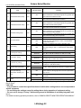
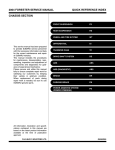
QUICK REFERENCE INDEX
BODY SECTION
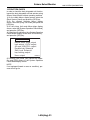
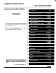
This service manual has been prepared
to provide SUBARU service personnel
with the necessary information and data
for the correct maintenance and repair
of SUBARU vehicles.
This manual includes the procedures
for maintenance, disassembling, reassembling, inspection and adjustment of
components and diagnostics for guidance of experienced mechanics.
Please peruse and utilize this manual
fully to ensure complete repair work for
satisfying our customers by keeping
their vehicle in optimum condition.
When replacement of parts during
repair work is needed, be sure to use
SUBARU genuine parts.
All information, illustration and specifications contained in this manual are
based on the latest product information
available at the time of publication
approval.
FUJI HEAVY INDUSTRIES LTD.
HVAC SYSTEM
(HEATER, VENTILATOR AND A/C)
AC
HVAC SYSTEM (AUTO A/C)
(DIAGNOSTICS)
AC(diag)
AIRBAG SYSTEM
AB
AIRBAG SYSTEM (DIAGNOSTICS)
AB(diag)
SEAT BELT SYSTEM
SB
LIGHTING SYSTEM
LI
WIPER AND WASHER SYSTEMS
WW
ENTERTAINMENT
ET
COMMUNICATION SYSTEM
COM
GLASS/WINDOWS/MIRRORS
GW
BODY STRUCTURE
BS
INSTRUMENTATION/DRIVER INFO
IDI
SEATS
SE
SECURITY AND LOCKS
SL
SUNROOF/T-TOP/CONVERTIBLE TOP
(SUNROOF)
SR
EXTERIOR/INTERIOR TRIM
EI
EXTERIOR BODY PANELS
EB
G2320GE7
2003 LEGACY SERVICE MANUAL
QUICK REFERENCE INDEX
BODY SECTION
CRUISE CONTROL SYSTEM
CC
CRUISE CONTROL SYSTEM
(DIAGNOSTICS)
CC(diag)
IMMOBILIZER (DIAGNOSTICS)
IM(diag)
LAN SYSTEM (DIAGNOSTICS)
LAN(diag)
G2320GE7
LAN SYSTEM (DIAGNOSTICS)
LAN(diag)
1.
2.
3.
4.
5.
6.
7.
8.
9.
10.
11.
12.
13.
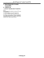
Page
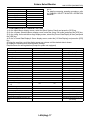
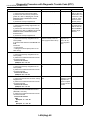
Basic Diagnostic Procedure ........................................................................2
Check List for Interview...............................................................................3
General Description ....................................................................................5
Electrical Component Location ...................................................................7
Control Module I/O Signal ...........................................................................9
Subaru Select Monitor...............................................................................14
Read Diagnostic Trouble Code (DTC) ......................................................24
Clear Memory Mode..................................................................................25
Read Current Data ....................................................................................26
Function Setting (Customize)....................................................................27
List of Diagnostic Trouble Code (DTC) .....................................................28
Diagnostic Procedure with Diagnostic Trouble Code (DTC) .....................30
General Diagnostic Table..........................................................................79
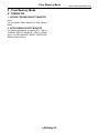
Basic Diagnostic Procedure
LAN SYSTEM (DIAGNOSTICS)
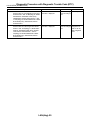
1. Basic Diagnostic Procedure
A: PROCEDURE
1. WITH SUBARU SELECT MONITOR
CAUTION:
• Subaru Select Monitor is required for reading DTC, performing diagnosis and reading current data.
• Remove foreign matter (dust, water and oil etc.) from the body integrated unit connector during removal and installation.
• For the model with immobilizer, registration of immobilizer may be needed after the replacement of
controller and etc. For detail procedure, refer to “REGISTRATION MANUAL FOR IMMOBILIZER”.
NOTE:
• To check harness for broken wires or short circuits, shake it while holding it or the connector.
• Check List for Interview <Ref. to LAN(diag)-3, Check List for Interview.>
1
2
3
4
5
Step
CHECK PRE-INSPECTION.
1) Ask the customer when and how the trouble occurred using interview check list. <Ref. to
LAN(diag)-3, Check List for Interview.>
2) Check the display of freeze frame data.
(Combination meter, odo/trip meter)
BASIC INSPECTION.
Check the components which might affect
body control. <Ref. to LAN(diag)-5, INSPECTION, General Description.>
CHECK INDICATION OF DTC.
1) Read the DTC. <Ref. to LAN(diag)-14,
READ DIAGNOSTIC TROUBLE CODE (DTC),
OPERATION, Subaru Select Monitor.>
Check
Is freeze frame data displayed?
Yes
Go to step 3.
No
Go to step 2.
Is the component that might
influence the body control
problem normal?
Go to step 3.
Repair or replace
each unit.
Is DTC displayed?
Go to step 5.
Go to step 4.
NOTE:
If the communication function of the Subaru Select Monitor cannot be executed normally,
check the communication circuit. <Ref. to
LAN(diag)-30, COMMUNICATION FOR INITIALIZING IMPOSSIBLE, Diagnostic Procedure with Diagnostic Trouble Code (DTC).>
2) Record all DTCs and freeze frame data.
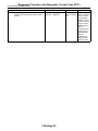
PERFORM THE GENERAL DIAGNOSTICS. Is result of inspection OK?
Inspect using “General Diagnostics Table”.
<Ref. to LAN(diag)-79, General Diagnostic
Table.>
PERFORM THE DIAGNOSIS.
Is DTC displayed?
1) Fix the wrong part.
2) Perform the clear memory mode. <Ref. to
LAN(diag)-20, CLEAR MEMORY MODE,
OPERATION, Subaru Select Monitor.>
3) Read DTC. <Ref. to LAN(diag)-14, READ
DIAGNOSTIC TROUBLE CODE (DTC),
OPERATION, Subaru Select Monitor.>
LAN(diag)-2
LAN system is nor- Go to step 5.
mal.
Repeat step 5 until Finish the diagnoDTC is not shown. sis.
Check List for Interview
LAN SYSTEM (DIAGNOSTICS)
2. Check List for Interview
A: CHECK
Inspect the following items about the vehicle’s state.
1. DISPLAY OF FREEZE FRAME DATA
Freeze frame data is displayed in odo/trip meter.
Ignition key position
Timing
When and how often are they displayed?
❏ Always
❏ Sometimes
❏ Only once
Which freeze frame data is displayed? (Record them all)
❏ Er IU (Fail in the body integrated unit)
❏ Er HC (Fail of high-speed CAN)
❏ Er LC (Fail of low-speed CAN)
❏ Er −− (Fails of both high-speed and low-speed CAN)
❏ Er EG (Fail of EGI communication counter)
❏ Er TC (Fail of TCM communication counter)
❏ Er Ab (Fail of vehicle dynamics control (VDC)/ABS communication counter)
❏ OFF
❏ ACC
❏ ON (before starting engine)
❏ START
❏ ON (after Engine starting, engine is running)
❏ ON (after Engine starting, engine is at a standstill)
❏ Immediately after turning the ignition to ON
❏ Immediately after turning the ignition to START
2. DISPLAY IN COMBINATION METER
Display in combination
meter
Center display
Display of other indicators
❏ OK / ❏ NG
❏ OK / ❏ NG
❏ OK / ❏ NG
❏ ON / ❏ OFF
❏ ON / ❏ OFF
❏ ON / ❏ OFF
a) Display of temperature gauge
b) Display of fuel gauge
c) Display of ambient temperature
d) Malfunction indicator light
e) SPORT indicator light (AT warning light)
f) ABS warning light/Vehicle dynamics control (VDC) warning
light
g) Immobilizer indicator light
h) Seat belt warning light (Driver’s seat)
i) Seat belt warning light (Passenger’s seat)
❏ ON / ❏ Blink / ❏ OFF
❏ ON / ❏ OFF
❏ ON / ❏ OFF
a)
b)
c)
d)
e)
f)
g)
h)
i)
j)
k)
l)
❏ Yes / ❏ No
❏ Yes / ❏ No
❏ Yes / ❏ No
❏ Yes / ❏ No
❏ Yes / ❏ No
❏ Yes / ❏ No
❏ Yes / ❏ No
❏ Yes / ❏ No
❏ Yes / ❏ No
❏ Yes / ❏ No
❏ Yes / ❏ No
❏ Yes / ❏ No
3. SYMPTOMS
Behavior of vehicle
Illumination volume control is not available.
Rear wiper does not operate.
Wiper deicer does not operate.
Rear defogger does not operate.
Door lock does not operate.
Trunk/rear gate lock does not operate
Driver’s door lock does not operate.
Shift lock does not operate.
Rear fog light does not come on.
Double lock does not operate. (EK model)
Heater cock valve does not operate.
Key illumination blinks.
LAN(diag)-3
Check List for Interview
LAN SYSTEM (DIAGNOSTICS)
4. CONDITIONS UNDER WHICH TROUBLE OCCURS
Driving condition
❏ At standstill (While idling)
❏ When the vehicle is running
Vehicle speed
❏ When accelerating
Acceleration
❏ Decelerating (With braking)
Deceleration
❏ Decelerating (Without braking) Deceleration
❏ Flat road
❏ Uphill
❏ Downhill
❏ Gravel road
❏ Bumpy road
❏ Snowy road
Does it occur when operating any part?
Operated part:
Trouble Symptom:
Are other troubles occurred?
From where:
Trouble Symptom:
LAN(diag)-4
km/h (MPH)
km/h (MPH) to km/h (MPH)
km/h (MPH) to km/h (MPH)
km/h (MPH) to km/h (MPH)
General Description
LAN SYSTEM (DIAGNOSTICS)
3. General Description
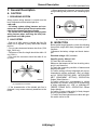
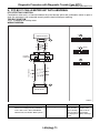
• When repairing the harness, connect the wires
using soldering and protect it with insulating tape,
etc.
A: CAUTION
1. SRS AIRBAG SYSTEM
Airbag system wiring harness is routed near the
body integrated unit and twisted pair line.
(A)
CAUTION:
• All airbag system wiring harness and connectors are colored yellow. Do not use the electrical test equipment on these circuits.
• Be careful not to damage the Airbag system
wiring harness when servicing the body integrated unit and LAN system.
LAN00080
(A) Soldering and protection with insulating tape
2. LAN SYSTEM
• Bus line of LAN system is twisted pair line. Be
careful not to bypass or partly unbind the twisted
pair line.
• Do not make clearance between bus lines (CAN
High, CAN Low).
• Difference of bus line length should be within 10
cm (3.94 in).
• Fray near the connector should be within 8 cm
(3.94 in).
(A)
LAN00081
(A) Bypass wire connection
• If the characteristics of the twisted pair line is
changed, it may cause extremely weakness to the
noise.
B: INSPECTION
Before performing diagnostics, check the following
items which might affect body integrated unit malfunctions.
1) Measure the battery voltage and check electrolyte.
Standard voltage: 12 V, or more
Specific gravity: Above 1.260
2) Check the fuse condition.
Make sure that ampere of the fuse is setting value,
and it is not blown out.
3) Check the connecting condition of harness and
harness connector.
4) Confirm settings of body integrated unit are corresponded to vehicle equipment. <Ref. to LAN(diag)-18, REGISTRATION BODY INTEGRATED
UNIT (EQUIPMENT SETTING), OPERATION,
Subaru Select Monitor.>
5) Confirm setting are corresponded to vehicle
equipment by function setting (ECM customizing)
of body integrated unit. <Ref. to LAN(diag)-20,
FREEZE FRAME DATA, OPERATION, Subaru
Select Monitor.>
6) Confirm “Factory initial setting” of body integrated unit registrations is “Market”.
7) Confirm key illumination does not blink with ignition switch turned to ON.
LAN(diag)-5
General Description
LAN SYSTEM (DIAGNOSTICS)
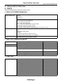
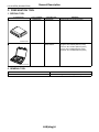
C: PREPARATION TOOL
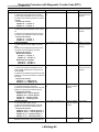
1. SPECIAL TOOL
ILLUSTRATION
TOOL NUMBER
24082AA230
DESCRIPTION
CARTRIDGE
REMARKS
Troubleshooting for electrical system.
22771AA030
SUBARU SELECT
MONITOR KIT
Troubleshooting for electrical system.
• English: 22771AA030 (Without printer)
• German: 22771AA070 (Without printer)
• French: 22771AA080 (Without printer)
• Spanish: 22771AA090 (Without printer)
ST24082AA230
ST22771AA030
2. GENERAL TOOL
TOOL NAME
Circuit tester
REMARKS
Used for measuring resistance, voltage and ampere.
LAN(diag)-6
Electrical Component Location
LAN SYSTEM (DIAGNOSTICS)
4. Electrical Component Location
A: LOCATION
(8)
(11)
(5)
(7)
(6)
(9)
(12)
(4)
(3)
(2)
(10)
(1)
LAN00101
(1)
(2)
(3)
(4)
(5)
Body integrated unit
Engine control module (ECM)
Auto A/C control unit
Navigation module
Keyless entry control unit
(Antenna)
(6)
(7)
(8)
(9)
A/C control panel
Center display
Transmission control module
(TCM)
(10)
(11)
Steering angle sensor
ABSCM&H/U or VDCCM&H/U (In
engine compartment)
(12)
Odo/trip meter
Combination meter
(3)
(1)
(2)
LAN00102
LAN(diag)-7
LAN00103
Electrical Component Location
LAN SYSTEM (DIAGNOSTICS)
(5)
(6)
(4)
LAN00104
LAN00105
(7)
(8)
LAN00007
LAN00106
(9)
(11)
(10)
LAN00107
8
P
R
N
D
60
km/h
140
40
F
160
20
180
0
SPORT
E
CRUISE
(12)
SET
LAN00111
LAN(diag)-8
LAN00008
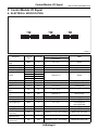
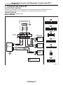
Control Module I/O Signal
LAN SYSTEM (DIAGNOSTICS)
5. Control Module I/O Signal
A: ELECTRICAL SPECIFICATION
A:
B: B280
i84
C: B281
1 2 3
4 5
6 7
8 9 10 11 12 13 14 15 16 17 18 19 20
23 24 25
26 27
28 29 30
21 22
1 2
3 4
5 6
7 8
9 10 11 12 13 14 15 16 17 18 19 20 21 22 23
24 25
26 27 28 29
30 31 32 33
34 35
4 5 6 7
1 2 3
8 9 10 11 12 13 14 15 16 17 18 19
27 28
22 23
24 25 26
20 21
LAN00012
Connector
No.
Terminal No.
Signal (V or Ω)
Ignition switch ON
(engine OFF)
NOTE
B281
C2
10 — 13 V
Always
B280
i84
i84
i84
B281
B281
B280
B281
B281
B7
A1
A24
A21
C9
C8
B22
C7
C23
10 — 13 V
10 — 13 V
10 — 13 V
Always
Ignition ON
ACC ON
Less than 1 Ω
Always
10 — 13 V
10 — 13 V
When ignition key inserted
When brake pedal depressed
i84
A10
4.5 — 5.5 V
Small light ON
i84
A2
0.5 — 4.5 V
—
i84
A25
Less than 1 Ω
Ground circuit
i84
B281
A5
C17
10 — 13 V
10 — 13 V
Rear fog light input
B281
C4
10 — 13 V
Rear fog light output
Headlight input
Door switch input
Driver’s seat
Door switch input
Passenger’s seat
Door switch input
Rear RH seat
B280
B281
B13
C16
10 — 13 V
10 — 13 V
Small light ON
Front fog light ON
Small light ON
Front fog light ON
Rear fog light ON
Rear fog light ON
Headlight ON (Both of Hi, Lo)
i84
A19
Less than 1 V (10 — 13 V at OFF)
Driver’s door open (ON)
i84
A32
Less than 1 V (10 — 13 V at OFF)
Passenger’s door open (ON)
i84
A18
Less than 1 V (10 — 13 V at OFF)
Rear RH door open (ON)
Description
System control power
supply
Backup power supply
Ignition power supply
ACC power supply
Ground
Key warning switch
Stop light switch
Illumination volume
(Vi1)
Illumination volume
(Vi 2)
Illumination volume
(Vi 3)
Illumination output
Front fog light input
LAN(diag)-9
Control Module I/O Signal
LAN SYSTEM (DIAGNOSTICS)
Connector
No.
Terminal No.
Signal (V or Ω)
Ignition switch ON
(engine OFF)
NOTE
i84
A31
Less than 1 V (10 — 13 V at OFF)
Rear LH door open (ON)
i84
A17
Less than 1 V (10 — 13 V at OFF)
Trunk/Rear gate open (ON)
i84
A30
10 — 13 V (at dimmer ON)
i84
A15
Less than 1 Ω
Extinct the clock and audio illumination
Door lock switch ON
i84
A29
Less than 1 Ω
Door lock switch ON
i84
i84
A34
A7
10 — 13 V
10 — 13 V
Manual, door key switch ON
i84
A8
10 — 13 V
Manual, door key switch ON
i84
A22
10 — 13 V
When the trunk open signal
received with keyless entry
(Sedan model)
Key/shift lock power
supply
B281
C1
10 — 13 V
Shift lock output
B280
B6
10 — 13 V
i84
A14
Less than 1 Ω
Ignition switch ON, at “P” range,
foot brake ON
Wiper deicer switch ON
B280
B14
Less than 1 Ω
Wiper deicer relay ON
Description
Door switch input
Rear LH seat
Door switch
Trunk/Rear gate
Illumination control
switch
Manual switch (LOCK)
Manual switch
(UNLOCK)
Door lock power supply
All door LOCK output
All door UNLOCK output
Trunk/Rear gate
UNLOCK output
Wiper deicer switch
Wiper deicer relay output
Rear defogger switch
Rear defogger relay
output
Shift switch (ON)
Shift switch (UP)
Shift switch (DOWN)
“P” range switch
i84
A28
Less than 1 Ω
Rear defogger switch ON
B281
B16
Less than 1 Ω
Rear defogger relay ON
B281
B281
B281
B281
C26
C15
C25
C13
Less than 1 Ω
Less than 1 Ω
Less than 1 Ω
Less than 1 Ω
At Manual mode
At Manual mode UP
At Manual mode DOWN
Impact sensor
B281
C5
Less than 1 Ω
Impact sensor ON
(Model with immobilizer)
Fuel level sensor
B281
B281
B281
C19
C3
C10
0 — 102.3 Ω
0.5 — 4.5 V
Less than 1 Ω
SIG
GND
i84
A4
Less than 1 Ω
Driver’s seat belt worn
i84
A13
Less than 1 Ω
Passenger’s seat belt worn
i84
A20
Less than 1 Ω
Driver’s seat belt worn
B281
C24
Less than 1 Ω
Passenger’s seat belt worn
B281
C11
B281
B281
B281
C6
C18
C27
Sedan 10 — 13 V
Wagon 0 — 5 V
Less than 1 Ω
Less than 1 Ω
Less than 1 Ω
Rear wiper switch ON
Rear wiper switch ON
Rear washer switch ON
B280
B21
10 — 13 V
B280
B1
B280
B8
10 — 13 V
Less than 1 Ω
B1 — B8 1 Ω or less
Ambient sensor
Seat belt switch
(driver’s seat)
Seat belt switch
(passenger’s seat)
Seat belt warning light
(driver’s seat)
Seat belt warning light
(passenger’s seat)
Sedan/Wagon identification switch
Rear wiper switch (ON)
Rear wiper switch (INT)
Rear washer switch
Rear wiper power supply
Rear wiper ON output
Rear wiper return
LAN(diag)-10
Rear wiper switch ON
At wiper reversing
Control Module I/O Signal
LAN SYSTEM (DIAGNOSTICS)
Connector
No.
Terminal No.
Signal (V or Ω)
Ignition switch ON
(engine OFF)
Room light output
B280
B3
Less than 1 Ω
Key ring illumination
output
B280
B4
Less than 1 Ω
Turn hazard output
B280
B12
Less than 1 Ω
Keyless buzzer output
i84
A6
Less than 1 Ω
Immobilizer pilot light
i84
A33
Less than 1 Ω
B280
i84
B12
A9
Less than 1 Ω
2 — 10 V
When LOCK, UNLOCK with keyless entry
Ignition key removed, driver door
open
When operating keyless entry
answer back
When operating keyless entry
answer back
At ignition key removed, immobilizer operating
Kick down switch ON
At keyless entry signal received
B280
B20
B280
B30
Between B20 — B30
Serial communication
At communicating
(sending and receiving)
i84
A26
i84
A25
Between A25 — A26
Serial communication
At communicating
(sending and receiving)
B280
B26
B280
B27
Between B25 — B27
Serial communication
At communicating
(sending and receiving)
(Model with auto A/C)
B281
C20 — C21
B18
(Back-up
B28)
Description
Kick down switch
Keyless communication
High-speed CAN circuit
(Hi)
High-speed CAN circuit
(Lo)
Low-speed CAN circuit
1 (Hi)
Low-speed CAN circuit
1 (Lo)
Low-speed CAN circuit
2 (Hi)
Low-speed CAN circuit
2 (Lo)
Immobilizer antenna
Immobilizer communication
(Main)
Subaru Select Monitor
communication
B280
B280
B19
Serial communication
Serial communication
Serial communication
LAN(diag)-11
NOTE
Control Module I/O Signal
LAN SYSTEM (DIAGNOSTICS)
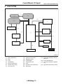
B: WIRING DIAGRAM
SYSTEM CONTROL POWER SUPPLY
C2
C13
"P" RANGE SWITCH
BACKUP POWER SUPPLY
B7
C26
SHIFT SWITCH (ON)
IGNITION POWER SUPPLY
A1
C15
SHIFT SWITCH (UP)
ACC POWER SUPPLY
A24
C25
SHIFT SWITCH (DOWN)
GROUND
A21
C19
FUEL LEVEL SENSOR
GROUND
C9
GROUND
C8
GROUND
B22
KEY WARNING SWITCH
C7
STOP LIGHT SWITCH
(AT MODEL)
ILLUMINATION OUTPUT
FRONT FOG LIGHT INPUT
REAR FOG LIGHT INPUT
REAR FOG LIGHT OUTPUT
HEADLIGHT INPUT
DOOR
SWITCH
INPUT
DRIVER'S SEAT
PASSENGER'S SEAT
REAR SEAT (RIGHT SIDE)
REAR SEAT (LEFT SIDE)
AMBIENT SENSOR (SIG)
AMBIENT SENSOR (GND)
A4
SEAT BELT SWITCH (DRIVER'S SEAT)
A13
C23
A20
A2
A10
ILLUMINATION
VOLUME
C3
C10
B27
A25
C11
SEDAN / WAGON IDENTIFICATION SWITCH
A5
C17
C22
REGISTRATION MODE SWITCH
(EXCEPT FOR EK MODEL)
KEYLESS COMMUNICATION
C4
B13
C16
A19
A32
A18
A31
TRUNK / REAR GATE
ENGINE HOOD SWITCH
A17
A16
ILLUMINATION CONTROL SWITCH (CLOCK)
A30
HEATER COCK VALVE OUTPUT
B15
A:
i84
B: B280
C: B281
BODY
INTEGRATED
UNIT
A9
B20
B30
HIGH-SPEED CAN CIRCUIT (HI)
HIGH-SPEED CAN CIRCUIT (LO)
A26
LOW-SPEED CAN CIRCUIT 1 (HI)
A27
LOW-SPEED CAN CIRCUIT 1 (LO)
B26
LOW-SPEED CAN CIRCUIT 2 (HI)
B25
LOW-SPEED CAN CIRCUIT 2 (LO)
C20
C21
MANUAL SWITCH (LOCK)
MANUAL SWITCH (UNLOCK)
DOOR LOCK POWER SUPPLY
ALL DOORS LOCK OUTPUT
ALL DOORS UNLOCK OUTPUT
DRIVER'S SEAT DOOR LOCK
(EXCEPT FOR EK MODEL)
TRUNK / REAR GATE UNLOCK OUTPUT
DOUBLE LOCK OUTPUT (EK MODEL)
SHIFT LOCK POWER SUPPLY
SHIFT LOCK OUTPUT
B18
B28
A15
A29
A34
A7
A8
REAR WIPER SWITCH (ON)
REAR WIPER SWITCH (INT)
C28
REAR WASHER SWITCH
B21
REAR WIPER POWER SUPPLY
A23
B1
REAR WIPER ON OUTPUT
A22
B8
REAR WIPER RETURN
A35
C1
B6
B3
ROOM LIGHT OUTPUT
B4
KEY RING ILLUMINATION OUTPUT
B12
TURN HAZARD OUTPUT
IMMOBILIZER PILOT LIGHT
A33
WIPER DEICER RELAY OUTPUT
B14
C22
REAR DEFOGGER SWITCH
(MODEL WITH MANUAL A/C)
A28
REAR DEFOGGER RELAY OUTPUT
B16
B11
(BLUE)
1 2
3 4
5 6
7 8
9 10 11 12 13 14 15 16 17 18 19 20 21 22 23
24 25
26 27 28 29
30 31 32 33
34 35
IMMOBILIZER COMMUNICATION (MAIN)
IMMOBILIZER COMMUNICATION (BACKUP)
C6
A14
i84
IMMOBILIZER ANTENNA
C18
WIPER DEICER SWITCH
A:
SEAT BELT SWITCH (PASSENGER'S SEAT)
SEAT BELT WARNING LIGHT
(DRIVER'S SEAT)
SEAT BELT WARNING LIGHT
(PASSENGER'S SEAT)
ALARM CONTROL ECM (EK MODEL)
B11
SECURITY HORN OUTPUT
(EXCEPT FOR EK MODEL)
B19
SUBARU SELECT MONITOR
COMMUNICATION
B: B280
1 2 3
4 5
6 7
8 9 10 11 12 13 14 15 16 17 18 19 20
21 22
23 24 25
26 27
28 29 30
C: B281
4 5 6 7
1 2 3
8 9 10 11 12 13 14 15 16 17 18 19
27 28
22 23
24 25 26
20 21
LAN00108
LAN(diag)-12
Control Module I/O Signal
LAN SYSTEM (DIAGNOSTICS)
C: LAN SYSTEM
(13)
(12)
(11)
(13)
(10)
(2)
(13)
(9)
(14)
(18)
(3)
(17)
(1)
(8)
(15)
(13)
(4)
(7)
(13)
(5)
(16)
(6)
LAN00109
(1)
(2)
(3)
(4)
(5)
(6)
(7)
Body integrated unit
ECM
TCM
VDC/ABSCM
Steering angle sensor
Keyless entry receiver
A/C control unit
(8)
(9)
(10)
(11)
(12)
(13)
(14)
Audio⋅A/C control panel
Navigation system
Center display
Combination meter
Clock
Exclusive communication line
IE-Bus (AV)
LAN(diag)-13
(15)
Subaru Select Monitor communication line
(16)
(17)
Subaru Select Monitor
Low speed CAN (Body integrated
unit)
(18)
High speed CAN (Driving control)
Subaru Select Monitor
LAN SYSTEM (DIAGNOSTICS)
6. Subaru Select Monitor
A: OPERATION
1. READ DIAGNOSTIC TROUBLE CODE
(DTC)
CAUTION:
Do not connect scan tools except for Subaru
Select Monitor.
5) Turn the ignition switch to ON (engine OFF) and
turn the Subaru Select Monitor switch to ON.
NOTE:
• DTC is displayed in the sequence of inputting.
(When inputting more than two simultaneously,
DTC is displayed in the sequence of priority.)
• When more than two DTCs are displayed, perform the diagnosis of top of them.
1) Prepare the Subaru Select Monitor kit.
(A)
LAN00017
(A) Power switch
LAN00014
2) Connect the diagnosis cable to Subaru Select
Monitor.
3) Insert the cartridge to Subaru Select Monitor.
<Ref. to LAN(diag)-6, SPECIAL TOOL, PREPARATION TOOL, General Description.>
6) On the «Main Menu» display screen, select the
{Each System Check} and press the [YES] key.
7) On the «System Selection Menu» display
screen, select the {Integ. Unit mode} and press the
[YES] key.
8) On the «Integ. Unit mode failuer diag» display
screen, select the {Diagnostic Code(s) Display}
and press the [YES] key.
NOTE:
• For details concerning operation procedure, refer to “SUBARU SELECT MONITOR OPERATION
MANUAL”.
• For details concerning DTCs, refer to the List of
Diagnostic Trouble Code (DTC). <Ref. to LAN(diag)-28, List of Diagnostic Trouble Code (DTC).>
ST
LAN00015
4) Connect the Subaru Select Monitor to data link
connector.
Data link connector is located in the lower portion of
the instrument panel (on the driver’s side).
LAN00110
LAN(diag)-14
Subaru Select Monitor
LAN SYSTEM (DIAGNOSTICS)
2. READ CURRENT DATA
1) On the «Main Menu» display screen, select the {Each System Check} and press the [YES] key.
2) On the «System Selection Menu» display screen, select the {Integ. Unit mode} and press the [YES] key.
3) On the «Integ. Unit mode failuer diag» display screen, select the {Current Data Display & Save} and press
the [YES] key.
4) On the «Current Data Display & Save» display screen, select the {12 Data Display} and press the [YES]
key.
5) Using the scroll key, scroll the display screen up or down until the desired data is shown.
• A support list contains both of analog and digital data, and they are shown in the following table.
3. DISPLAY OF ANALOG DATA
Items to be displayed
BATT Voltage (Control)
BATT Voltage (BACK UP)
IG power supply voltage
ACC voltage
Illumination VR voltage
Illumi. output d-ratio
ambient temp sensor V
Ambient temperature
Fuel level voltage
Fuel level resistance
key-lock solenoid V
number of regist.
Front Wheel Speed
VDC/ABS latest f-code
DTC display (Temporarily)
Blower fan steps
Fuel level resistance2
Fuel consumption
Coolant Temp.
0 — 2 level
0 — 102.3 Ω
cc/s
−40 — 130°C
NOTE
—
—
—
—
—
—
—
—
—
Body integrated unit input value
—
—
—
This is normal when the DTC is not input
though the this code is displayed
0: OFF, 1: Low, 2: More than 2 level
Body integrated unit output
—
—
m/s2
—
Vehicle lateral G
SPORT Shift Stages
Shift Position
Off delay time
Auto lock time
Unit of measure
10 — 15 V
10 — 15 V
10 — 15 V
10 — 15 V
0—5V
0 — 100%
0—5V
−40 — 87.5°C
0—8V
0 — 102.3 Ω
6 — 12 V
0—4
km/h
0 — 7 levels
0 — 7 levels
OFF, Short, Normal, Long
20, 30, 40, 50, 60 seconds
LAN(diag)-15
(0: light OFF, 6: fail, 7: ATF temperature
High/Low)
(8 is no input)
—
—
Subaru Select Monitor
LAN SYSTEM (DIAGNOSTICS)
4. DISPLAY OF ON/OFF DATA
Items to be displayed
key-lock warning SW
Stop Light Switch
Front fog lamp SW input
Rear fog lamp SW input
lighting SW input
Door key-lock SW input
Door unlock SW input
Driver’s door SW input
P-door SW input
Rear right door SW input
Rear left door SW input
R Gate SW input
Manual lock SW input
Manual unlock SW input
Lock SW (front hood)
Bright SW input
Tiptronic Mode Switch
TIP UPSW input
TIP DOWN SW input
P SW
R wiper ON SW input
R wiper INT SW input
R washer SW input
wiper deicer SW input
Rear Defogger SW
Driver’s Seat SW input
P seatbelt SW input
Fr wiper input
Registration SW input
Identification SW input
Rr defogger output
lock actuat. LOCK output
All seat UNLOCK output
D-seat UNLOCK output
R gate/trunk UNLK output
Double lock output
R wiper output
Shift Lock Solenoid
Key locking output
wiper deicer SW input
Starter cutting output
Hazard Output
Keyless Buzzer Output
Horn Output
Siren Output
D-belt warning light O/P
P-belt warning light O/P
Illumination lamp O/P
Room lamp output
key illumi. lamp o/p
Unit of measure
ON/OFF
ON/OFF
ON/OFF
ON/OFF
ON/OFF
ON/OFF
ON/OFF
ON/OFF
ON/OFF
ON/OFF
ON/OFF
ON/OFF
ON/OFF
ON/OFF
ON/OFF
ON/OFF
ON/OFF
ON/OFF
ON/OFF
ON/OFF
ON/OFF
ON/OFF
ON/OFF
ON/OFF
ON/OFF
ON/OFF
ON/OFF
ON/OFF
ON/OFF
ON/OFF
ON/OFF
ON/OFF
ON/OFF
ON/OFF
ON/OFF
ON/OFF
ON/OFF
ON/OFF
ON/OFF
ON/OFF
ON/OFF
ON/OFF
ON/OFF
ON/OFF
ON/OFF
ON/OFF
ON/OFF
ON/OFF
ON/OFF
ON/OFF
Items to be displayed
R fog lamp output
R fog lamp monitor
Immobilizer lamp output
Keyless operation 1
Keyless operation 2
CC Main Lamp
CC Set Lamp
SPORT Lamp
SPORT Blink
ATF Temperature Lamp
ATF Blink
Tire diameter abnormal 1
Tire diameter abnormal 2
SPORT Shift (UP)
SPORT Shift (DOWN)
SPORT Shift (buzzer 1)
SPORT Shift (buzzer 2)
ABS/VDC Judging
ADA Existence Judging
Small lamp SW
Headlamp
Headlight HI
Turn signal LH
Turn signal RH
Rr Defogger SW
Australia Judging Flag
Tire 18inch flag
Number of cylinders
Cam shaft specification
Turbo
E/G displacement (2.5L)
E/G displacement (3.0L)
AT/MT identification terminal
E/G cooling fan
Heater cock valve
Power window (Up)
Power window (Down)
Keyless buzzer
Bright Request
P/W ECM Failure
Keyless Hook SW
Door lock SW (Open)
Door lock SW (Close)
Door Key SW (Open)
Door Key SW (Close)
Under hook registration
Hook registration end
Unlock request
Center display failure
NAVI Failure
IE Bus failure
LAN(diag)-16
Unit of measure
ON/OFF
ON/OFF
ON/OFF
Registration/Normal
Clear/Normal
On/Off
On/Off
On/Off
Blink/Off
On/Off
Blink/Off
On/Off
Blink/Off
UP/OFF
DOWN/OFF
ON/OFF
ON/OFF
ABS/VDC
Yes/No
ON/OFF
ON/OFF
ON/OFF
ON/OFF
ON/OFF
ON/OFF
Australia/Others
18 in/others
4 cylinders/6 cylinders
SOHC/DOHC
Turbo/Non-turbo
2.5 L/ OFF
3.0 L/ OFF
AT model/MT model
ON/OFF
ON/OFF
ON/OFF
ON/OFF
ON/OFF
ON/OFF
NG/OK
ON/OFF
ON/OFF
ON/OFF
ON/OFF
ON/OFF
ON/OFF
ON/OFF
ON/OFF
OK/NG
OK/NG
Can not use
Subaru Select Monitor
LAN SYSTEM (DIAGNOSTICS)
Items to be displayed
Auto A/C failure
EBD Warning Light
ABS Warning Light
VDC OFF flag
VDC/ABS OK B
VDC/ABS condition
Destinat.
Touch SW
Unit of measure
OK/NG
OK/OFF
OK/OFF
ON/OFF
OK/NG
0—4
0 — 16
0 — 64
NOTE:
For details concerning operation procedure, refer
to “SUBARU SELECT MONITOR OPERATION
MANUAL”.
5. CONFIRMATION OF CURRENT SETTING
1) On the «Main Menu» display screen, select the {Each System Check} and press the [YES] key.
2) On the «System Selection Menu» display screen, select the {Integ. Unit mode} and press the [YES] key.
3) On the «Integ. Unit mode failuer diag» display screen, select the {Current Data Display & Save} and press
the [YES] key.
4) On the «Current Data Display & Save» display screen, select the {12 Data Display} and press the [YES]
key.
5) Using the scroll key, scroll the display screen up or down until the desired data is shown.
6) Display the following items and record the settings.
Required items for new registration (Except for system not equipped)
Item
Key No. to register
Off delay
Auto-lock
Rr defogger op. mode
Wiper deicer op. mode
Security Alarm Setup
Impact Sensor Setup
Alarm monitor delay setting
Lockout prevention
Impact Sensor
Siren setting
Answer-back buzzer setup
Hazard answer-back setup
Automatic locking setup
Ans.-back Buzzer
Auto locking
Door open warning (prevention of battery
run-out)
A/C ECM setting
P/W ECM setting
Center display failure
Wiper deicer
Rear fog light setting
Factory initial setting
Security setting (Specified security setting)
Item to confirm
1
2
3
4
OFF
Long
Normal
Short
60, 50, 40, 30, 20
OFF
Normal
Continuous
Normal
Continuous
ON
OFF
ON
OFF
ON
OFF
ON
OFF
Yes
No
Yes
No
ON
OFF
ON
OFF
ON
OFF
Yes
No
Yes
No
Yes
No
Yes
Yes
Yes
Yes
Yes
Manufacture
No
No
No
No
No
Market
Yes
No
LAN(diag)-17
Remarks
Registered ID type
Setting for lighting off time
(Unit sec.)
Optional setting
Optional setting
Optional setting
Optional setting
Not equipped
Not equipped
Model with auto A/C
Not equipped
Model with center display
Optional setting
Optional setting
Not change to Manufacture mode
Operate the selected security set.
(EK model)
Subaru Select Monitor
LAN SYSTEM (DIAGNOSTICS)
6. REGISTRATION BODY INTEGRATED
UNIT (EQUIPMENT SETTING)
CAUTION:
Body integrated unit is core of LAN system, and
also can select the function of all vehicle system control. It is possible to control the original
functions of vehicle when registrations of body
integrated unit and function setting are corresponded to vehicle equipment.
If registrations and function setting are different from vehicle equipment, vehicle system
does not operate normally and diagnosis cannot be performed correctly. Pay attention to
items below.
• Be sure to correspond registrations and
function settings to vehicle equipment.
• Do not change the settings of vehicle improperly.
• Confirm key illumination does not blink or
“Factory initial setting” of body integrated unit
registrations is “Market”. If “Factory initial setting” is set to “Factory”, key illumination blinks
with ignition key turned to ON to give warning
of unconfirmed settings.
• Key illumination does not blink with ignition
switch turned to ON and go off with door
closed.
• Be sure to register immobilizer if body integrated unit is replaced with a new one. (Model
with immobilizer)
• Make a registration of immobilizer when the
parts replaced related to immobilizer. Refer to
“REGISTRATION MANUAL FOR IMMOBILIZER”.
1) Turn the ignition switch to OFF.
2) Connect the Subaru Select Monitor to data link
connector.
3) Turn the ignition switch to ON and Subaru Select
Monitor to ON.
(A)
LAN00017
(A) Power switch
4) On the «Main Menu» display screen, select the
{Each System Check} and press the [YES] key.
5) On the «Each System Check» display screen,
select the {Integ. Unit mode} and then select the
“ECM customizing”.
LAN00110
LAN(diag)-18
Subaru Select Monitor
LAN SYSTEM (DIAGNOSTICS)
6) Change the setting with UP/DOWN key and press the [YES] key.
• List of body integrated unit registration item
NOTE:
Setting is different depending on grade of vehicle.
Data
Initial setting
Registration
ON
21
A/C ECM setting
OFF
OFF
22
P/W ECM setting
OFF
23
Center display failure (OP)
OFF
24
Wiperdeicer (OP)
OFF
ON
OFF
ON
OFF
ON
OFF
ON
25
Rear fog light setting (OP)
OFF
OFF
26
Factory initial setting
(Reset of body integrated
unit)
Factory (Reset)
Factory
Market (Settlement)
Remarks
Illumination control does not operate if A/C ECM
setting is set to “OFF” in case of model with auto
A/C.
If A/C ECM setting is set to “ON” in case of model
without auto A/C, illumination change to night illumination and it is difficult to be recognized.
Be sure to set P/W ECM setting to “OFF”.
Auto-reverse function
Information may not be displayed on center display
if Center display failure is set to “OFF” in case of
model with center display.
ON signal does not output with operation of wiper
deicer switch if Wiperdeicer is set to “OFF” in
model with wiper deicer.
Vehicle is controlled in rear fog light equipped
mode.
Vehicle is controlled in rear fog light no-equipped
mode. (Be sure to set to “OFF” in model without
rear fog light.
If Factory initial setting is set to “Factory”, registrations of items above is changed to “OFF”. Be sure
to set to “Market”.
CAUTION:
• It is possible to control the original functions of vehicle when registrations of body integrated unit
and function setting are corresponded to vehicle equipment.
• When body integrated unit is new one or “Factory” mode, key illumination blinks to show equipment settings does not completed.
• Be sure not to change Factory initial setting except installation of new body integrated unit.
NOTE:
• “Factory” mode:
• Body integrated unit has been not set yet. It can be recognized by key illumination blinking with ignition
switch turned to ON.
• All body integrated units as part for repair are set to “Factory” mode. When replacing a body integrated
unit, be sure to perform the registration operation.
• “Market” mode:
Each settings have been set. It can be recognized by key illumination coming on in concocting with room
light and going off with ignition switch turned to ON.
LAN(diag)-19
Subaru Select Monitor
LAN SYSTEM (DIAGNOSTICS)
7) Perform the Factory setting. On the «ECM customizing» display screen of Subaru Select Monitor,
select the {Factory initial setting} and press the
[YES] key.
8) Change the mode from Factory into Market.
9) Replace the immobilizer cartridge, and register
the immobilizer key. (Model with immobilizer)
10) Perform the registration according to the procedures of “IMMOBILIZER REGISTRATION MANUAL”.
11) When key registration is completed, “Do you
want to register remote engine start?” is displayed.
Perform the registration only if equipped.
12) Perform the function setting (ECM customizing).
<Ref. to LAN(diag)-21, FUNCTION SETTING
(ECM CUSTOMIZING), OPERATION, Subaru Select Monitor.>
NOTE:
For details concerning operation procedure, refer
to “SUBARU SELECT MONITOR OPERATION
MANUAL”.
7. CLEAR MEMORY MODE
1) On the «Main Menu» display screen, select the
{2. Each System Check} and press the [YES] key.
2) On the «System Selection Menu» display
screen, select the {Integ. Unit mode} and press the
[YES] key.
3) Press [YES] key after displayed the information
of body integrated unit type.
4) On the «Integ. Unit mode failuer diag» display
screen, select the {Clear Memory} and press the
[YES] key.
Display
Clear memory?
Contents to be monitored
Clear function of DTC and
freeze frame data
5) When the “Done” are shown on the display
screen, turn the ignition switch to OFF.
NOTE:
For detailed operation procedure, refer to “SUBARU SELECT MONITOR OPERATION MANUAL”.
8. FREEZE FRAME DATA
NOTE:
• Data stored at the time of trouble occurrence is
shown on display.
• Freeze frame data will be memorized maximum
to 20.
• If freeze frame data is not stored in memory correctly (caused by low power supply of body integrated unit), DTC will be displayed with “?” on the
head of it in the Subaru Select Monitor display. This
shows it may be an unreliable reading.
LAN(diag)-20
Subaru Select Monitor
LAN SYSTEM (DIAGNOSTICS)
9. FUNCTION SETTING (ECM CUSTOMIZING)
1) On the «Main Menu» display screen, select the {Each System Check} and press the [YES] key.
2) On the «System Selection Menu» display screen, select the {Integ. Unit mode} and press the [YES] key.
3) On the «Integ. Unit mode failuer diag» display screen, select the {ECM customizing} and press the [YES]
key.
4) Change the setting with UP/DOWN key and press the [YES] key.
• List of function setting item (ECM customizing)
No.
Data
Initial
setting
value
1
Off delay time
Normal
2
Auto-lock time
30 sec.
3
Rr defogger op. mode
15 min.
Customize setting
Setting
OFF
Short
Normal
Long
0 — 60 seconds
15 min.
Continuation
15 min.
4
Wiper deicer op. mode
15 min.
Continuation
5
Security Alarm Setup
OFF
ON
OFF
ON
6
Impact Sensor Setup
OFF
OFF
7
Alarm monitor delay setting
ON
8
Lockout prevention
ON
ON
OFF
ON
OFF
9
Impact sensor (OP)
OFF
ON
OFF
10
Siren setting
OFF
ON
OFF
Remarks
Delay time below can be selected by setting.
After door closed
After key unlock
0 sec.
0 sec.
3 sec.
10 sec.
5 sec.
20 sec.
8 sec.
30 sec.
Workable when Auto locking is set to “ON” and Automatic
locking setup is “ON”
Time can be changed by 10 seconds: 0 (OFF) — 60 (maximum).
Rear defogger stops in 15 minutes automatically after
switch is turned to ON.
Rear defogger repeats active condition for 15 minutes and
inactive condition for 2 minutes until switch is turned to OFF.
Wiper deicer stops in 15 minutes automatically after switch
is turned to ON.
Wiper deicer repeats active condition for 15 minutes and
inactive condition for 2 minutes until switch is turned to OFF.
Security alarm (horn or siren) in active condition
Security alarm in inactive condition
Workable when Impact Sensor Setup is set to “ON”
Impact sensor in active condition
Impact sensor in inactive condition
(Set Impact Sensor Setup of model without impact sensor
to “OFF”.)
After doors are locked by keyless entry system operated,
Alarm monitor starts in following time.
Delay time is 30 seconds.
Delay time is 0 second.
Lockout prevention in active condition
(Lockout prevention does not operate if safety knob is
locked by hand.)
Lockout prevention in inactive condition
Vehicle is controlled in impact sensor equipped mode. (Set
Impact sensor to “OFF” in model without impact sensor. If
Impact sensor is set to “ON”, hazard, horn or siren operate
after doors are locked by keyless entry system operated
(Alarm monitor starting).
Vehicle is controlled in impact sensor no-equipped mode.
Siren sounds when alarm operates.
(Set Siren setting to “OFF” in model without siren. Horn
does not sound if Siren setting is set to “ON”.)
Horn sounds when alarm operates.
LAN(diag)-21
Subaru Select Monitor
LAN SYSTEM (DIAGNOSTICS)
No.
Data
Initial
setting
value
Customize setting
ON
11
Answer-back buzzer setup
ON
OFF
ON
12
Hazard answer-back setup
ON
OFF
ON
13
Automatic locking setup
ON
OFF
ON
14
Ans.-back Buzzer
ON
OFF
ON
15
Auto locking
ON
16
Initial Keyless Setting
—
17
Initial button setting
—
18
Initial Security setting
—
19
Passive Alarm (Not used)
20
Door open warning
(prevention of battery runout)
OFF
(Specification) Security
setup
OFF
OFF
—
Execution
—
Execution
—
21
OFF
Execution
ON
OFF
ON
OFF
ON
OFF
Remarks
Workable when Answer-back buzzer setup is set to “ON”
When lock/unlock is selected by keyless entry system operated, answer-back buzzer sounds.
When lock/unlock is selected by keyless entry system operated, answer-back buzzer does not sound.
Workable when Hazard answer-back setup is set to “ON”
When lock/unlock is selected by keyless entry system operated, hazard answer-back operates.
When lock/unlock is selected by keyless entry system operated, hazard answer-back does not operate.
Workable when Automatic locking setup is set to “ON”
When lock/unlock is selected by keyless entry system operated, automatic locking operates.
When lock/unlock is selected by keyless entry system operated, automatic locking does not operate.
Vehicle is controlled in answer-back buzzer equipped mode.
Vehicle is controlled in answer-back buzzer non-equipped
mode. (Set Ans.-back Buzzer to “OFF” in model without
answer back buzzer.)
Vehicle is controlled in auto locking equipped mode.
Vehicle is controlled in auto locking non-equipped mode.
(Set Auto locking to “OFF” in model without answer-back
buzzer.)
—
Settings of keyless entry system are initialized. (No. 2: 30
sec., No.11: ON, No.12: ON, No.13: ON, No.14: ON)
—
Settings of each function are initialized. (No. 1: Normal, No.
3: 15 min., No. 4: 15 min., No. 8: ON)
—
Settings of security system are initialized. (No. 5: OFF, No.
6: OFF, No. 7: ON, No.10: OFF)
Applicable to North America model (If Passive Alarm is set
to “ON”, nothing operates and there is no negative effect.)
If detecting door open for 30 minutes, room light, key illumination and door warning light are turned off to prevent battery run-out.
Room light, key illumination and door warning light is not
turned off.
Selected security settings in active condition (EK model)
Normally in active condition
5) After setting, make sure that vehicle equipment is same as the setting changed in the {Current Data Display & Save}.
CAUTION:
• It is possible to control the original functions of vehicle when settings above are corresponded to
vehicle equipment.
• Do not change the settings except for setting above during operation of equipment setting.
• Be sure not to change “Factory” initial setting except in installation of new body integrated unit.
NOTE:
For details concerning operation procedure, refer to “SUBARU SELECT MONITOR OPERATION MANUAL”.
LAN(diag)-22
Subaru Select Monitor
LAN SYSTEM (DIAGNOSTICS)
10.FUNCTION CHECK
In order to check the body integrated unit function,
inspect the body integrated unit and actuator using
Subaru Select Monitor without operating switches.
1) On the «Main Menu» display screen, select the
{Each System Check} and press the [YES] key.
2) On the «System Selection Menu» display
screen, select the {Integ. Unit mode} and press the
[YES] key.
3) On the «Integ. Unit mode failuer diag» display
screen, select the {System Operation Check Mode}
and press the [YES] key.
4) Select item to operate on the «System Operation
Check Mode» display screen with “UP/Down key”,
and press the [YES] key.
Function check
Heater cock valve output
lock actuat, LOCK output
All seat UNLOCK, output
Double lock Solenoid
Shift Lock Solenoid
key locking output
Horn output
LAN00018
5) Pressing [YES] starts, [NO] cancels the operation and [YES] returns to the System Operation
Check Mode display screen.
NOTE:
If not equipped (based on area or condition), process will not go on.
LAN(diag)-23
Read Diagnostic Trouble Code (DTC)
LAN SYSTEM (DIAGNOSTICS)
7. Read Diagnostic Trouble
Code (DTC)
A: OPERATION
1. WITHOUT SUBARU SELECT MONITOR
NOTE:
Use the Subaru Select Monitor, because DTCs can
not be read out.
2. WITH SUBARU SELECT MONITOR
For details concerning DTC reading procedure, refer to “Subaru Select Monitor”. <Ref. to LAN(diag)14, READ DIAGNOSTIC TROUBLE CODE (DTC),
OPERATION, Subaru Select Monitor.>
LAN(diag)-24
Clear Memory Mode
LAN SYSTEM (DIAGNOSTICS)
8. Clear Memory Mode
A: OPERATION
1. WITHOUT SUBARU SELECT MONITOR
NOTE:
Use the Subaru Select Monitor for Clear Memory
Mode.
2. WITH SUBARU SELECT MONITOR
For detailed procedures of clearing DTC, refer to
“SUBARU SELECT MONITOR”. <Ref. to LAN(diag)-20, CLEAR MEMORY MODE, OPERATION,
Subaru Select Monitor.>
LAN(diag)-25
Read Current Data
LAN SYSTEM (DIAGNOSTICS)
9. Read Current Data
A: OPERATION
1) On the «Main Menu» display screen, select the
{Each System Check} and press the [YES] key.
2) On the «System Selection Menu» display
screen, select the {Integ. Unit mode} and press the
[YES] key.
3) On the «Integ. Unit mode failuer diag» display
screen, select the {Current Data Display & Save}
and press the [YES] key.
4) On the «Data Display Menu» screen, select the
{12 Data Display} and press the [YES] key.
5) Using the scroll key, scroll the display screen up
or down until the desired data is shown.
<Ref. to LAN(diag)-15, DISPLAY OF ANALOG DATA, OPERATION, Subaru Select Monitor.> <Ref.
to LAN(diag)-16, DISPLAY OF ON/OFF DATA,
OPERATION, Subaru Select Monitor.> <Ref. to
LAN(diag)-17, CONFIRMATION OF CURRENT
SETTING, OPERATION, Subaru Select Monitor.>
LAN(diag)-26
Function Setting (Customize)
LAN SYSTEM (DIAGNOSTICS)
10.Function Setting (Customize)
A: OPERATION
1. WITHOUT SUBARU SELECT MONITOR
NOTE:
Applied to the Model with center display.
1) Display the information screen with pressing the
“INFO” switch of center display.
2) Select “SET” on the touch panel at the right top
of center display screen.
3) Select the item from “A: Keyless entry” or “B:
Various setup” on the touch panel.
(A)
(B)
LAN00112
4) Change the setting on the touch panel which
contains item to be changed.
5) Return to the information display screen and
complete it.
Function setting item list
Item
Keyless
Each function
Setting
Auto lock
Auto lock time setting
Answerback hazard
Room light delay time
Anti-lock out
Rear defogger
Wiper deicer
2. WITH SUBARU SELECT MONITOR
For detailed procedures of function setting (ECM
customizing), refer to “SUBARU SELECT MONITOR”. <Ref. to LAN(diag)-21, FUNCTION SETTING (ECM CUSTOMIZING), OPERATION,
Subaru Select Monitor.>
LAN(diag)-27
List of Diagnostic Trouble Code (DTC)
LAN SYSTEM (DIAGNOSTICS)
11.List of Diagnostic Trouble Code (DTC)
A: LIST
DTC
None
Item
Communication for initializing
impossible
Content of diagnosis
Open or short in Subaru
Select Monitor communication line.
None
DTC is not stored.
Internal error of combination meter.
B0100
Integ. unit system error
Body integrated unit internal error
B0101
BATT power supply (Control) error
Open or short in battery
power supply control circuit
B0102
BATT p/supply malfunction cont.
Open or short in BATT
power backup circuit
B0103
IGN power failure
Open or short in IGN
power supply circuit
B0104
ACC power failure
Open or short in ACC
power supply circuit
B0106
shift lock circuit Failure
Ground short of shift lock
circuit
B0107
R Fog lamp circuit Failure
Ground short of rear fog
circuit
B0201
High speed CAN fail ⋅ error counter
abnormal
Malfunction of high-speed
CAN communication
B0202
CAN-HS bus off
Any unit is cut communication.
B0211
CAN-HS (EGI) data abnormal
Received error data from
ECM.
B0212
CAN-HS (TCM) data abnormal
Received error data from
TCM.
B0213
CAN-HS VDC/ABS data abnormal
Received error data from
VDC/ABS unit.
B0221
CAN-HS ECM no-receive data
Not received error data
from ECM.
B0222
CAN-HS TCM no-receive data
Not received error data
from TCM
LAN(diag)-28
NOTE
<Ref. to LAN(diag)-30, COMMUNICATION
FOR INITIALIZING IMPOSSIBLE, Diagnostic
Procedure with Diagnostic Trouble Code
(DTC).>
<Ref. to LAN(diag)-33, DIAGNOSTIC TROUBLE CODE (DTC) IS NOT STORED, Diagnostic
Procedure with Diagnostic Trouble Code
(DTC).>
<Ref. to LAN(diag)-33, DTC B0100 INTEG.
UNIT SYSTEM ERROR, Diagnostic Procedure
with Diagnostic Trouble Code (DTC).>
<Ref. to LAN(diag)-34, DTC B0101 BATT P/
SUPPLY MALFUNCTION CONT., Diagnostic
Procedure with Diagnostic Trouble Code
(DTC).>
<Ref. to LAN(diag)-36, DTC B0102 BATT P/
SUPPLY MALFUNCTION CONT., Diagnostic
Procedure with Diagnostic Trouble Code
(DTC).>
<Ref. to LAN(diag)-38, DTC B0103 IGNITION
POWER FAILURE, Diagnostic Procedure with
Diagnostic Trouble Code (DTC).>
<Ref. to LAN(diag)-40, DTC B0104 ACC
POWER FAILURE, Diagnostic Procedure with
Diagnostic Trouble Code (DTC).>
<Ref. to LAN(diag)-42, DTC B0106 SHIFT
LOCK CIRCUIT FAILURE, Diagnostic Procedure with Diagnostic Trouble Code (DTC).>
<Ref. to LAN(diag)-44, DTC B0107 R FOG
LAMP CIRCUIT FAILURE, Diagnostic Procedure with Diagnostic Trouble Code (DTC).>
<Ref. to LAN(diag)-46, DTC B0201 CAN-HS
COUNTER ABNORMAL, Diagnostic Procedure
with Diagnostic Trouble Code (DTC).>
<Ref. to LAN(diag)-47, DTC B0202 CAN-HS
BUS OFF, Diagnostic Procedure with Diagnostic Trouble Code (DTC).>
<Ref. to LAN(diag)-51, DTC B0211 CAN-HS
ECM DATA ABNORMAL, Diagnostic Procedure
with Diagnostic Trouble Code (DTC).>
<Ref. to LAN(diag)-53, DTC B0212 CAN-HS
TCM DATA ABNORMAL, Diagnostic Procedure
with Diagnostic Trouble Code (DTC).>
<Ref. to LAN(diag)-54, DTC B0213 CAN-HS
VDC/ABS DATA ABNORMAL, Diagnostic Procedure with Diagnostic Trouble Code (DTC).>
<Ref. to LAN(diag)-56, DTC B0221 CAN-HS
ECM NO-RECEIVE DATA, Diagnostic Procedure with Diagnostic Trouble Code (DTC).>
<Ref. to LAN(diag)-60, DTC B0222 CAN-HS
TCM NO-RECEIVE DATA, Diagnostic Procedure with Diagnostic Trouble Code (DTC).>
List of Diagnostic Trouble Code (DTC)
LAN SYSTEM (DIAGNOSTICS)
DTC
B0223
Item
CAN-HS VDC/ABS no-receive
data
Content of diagnosis
Not received error data
from VDC/ABS unit.
B0300
CAN-LS malfunction
B0301
CAN-LS fail / error counter abnormal
Open or short in lowspeed CAN circuit, on
each side or both sides.
Malfunction of low-speed
CAN communication
B0302
CAN-LS bus off
Any unit is cut communication.
B0311
CAN-LS meter unit data abnormal
Received error data from
meter.
B0313
CAN-LS monitor data abnormal
Received error data from
monitor unit.
B0321
CAN-LS meter no-receive data
Not received error data
from meter
B0401
M collation NG
B0402
Immobilizer Key collation NG
B0403
E/G request NG
B0500
Keyless UART com. Malfunction
Malfunction related immobilizer
Malfunction related immobilizer
Malfunction related immobilizer
Open or short circuit in
keyless UART circuit
LAN(diag)-29
NOTE
<Ref. to LAN(diag)-62, DTC B0223 CAN-HS
VDC/ABS NO-RECEIVE DATA, Diagnostic Procedure with Diagnostic Trouble Code (DTC).>
<Ref. to LAN(diag)-65, DTC B0300 CAN-LS
MALFUNCTION, Diagnostic Procedure with
Diagnostic Trouble Code (DTC).>
<Ref. to LAN(diag)-68, DTC B0301 CAN-LS
COUNTER ABNORMAL, Diagnostic Procedure
with Diagnostic Trouble Code (DTC).>
<Ref. to LAN(diag)-70, DTC B0302 CAN-LS
BUS OFF, Diagnostic Procedure with Diagnostic Trouble Code (DTC).>
<Ref. to LAN(diag)-73, DTC B0311 CAN-LS
METER UNIT DATA ABNORMAL, Diagnostic
Procedure with Diagnostic Trouble Code
(DTC).>
<Ref. to LAN(diag)-74, DTC B0313 CAN-LS
MONITOR DATA ABNORMAL, Diagnostic Procedure with Diagnostic Trouble Code (DTC).>
<Ref. to LAN(diag)-75, DTC B0321 CAN-LS
METER NO-RECEIVE DATA, Diagnostic Procedure with Diagnostic Trouble Code (DTC).>
<Ref. to IM(diag)-15, List of Diagnostic Trouble
Code (DTC).>
<Ref. to IM(diag)-15, List of Diagnostic Trouble
Code (DTC).>
<Ref. to IM(diag)-15, List of Diagnostic Trouble
Code (DTC).>
<Ref. to LAN(diag)-77, DTC B0500 KEYLESS
UART COM. MALFUNCTION, Diagnostic Procedure with Diagnostic Trouble Code (DTC).>
Diagnostic Procedure with Diagnostic Trouble Code (DTC)
LAN SYSTEM (DIAGNOSTICS)
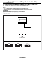
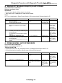
12.Diagnostic Procedure with Diagnostic Trouble Code (DTC)
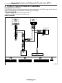
A: COMMUNICATION FOR INITIALIZING IMPOSSIBLE
NOTE:
• DTC is displayed in the sequence of the amount of counter numbers.
• When more than two DTCs are displayed, perform the diagnosis of top of them.
DIAGNOSIS:
Subaru Select Monitor communication line is open or shorted.
TROUBLE SYMPTOM:
Not communicable with Subaru Select Monitor.
WIRING DIAGRAM:
A:
i84
BODY INTEGRATED UNIT
A1
B19
B: B280
10
IGNITION RELAY
B40
DATA LINK CONNECTOR
A:
i84
1 2
3 4
5 6
7 8
9 10 11 12 13 14 15 16 17 18 19 20 21 22 23
24 25
26 27 28 29
30 31 32 33
34 35
B40
B: B280
4 5 6 7
1 2 3
8 9 10 11 12 13 14 15 16 17 18 19
27 28
22 23
24 25 26
20 21
(BLACK)
1 2 3 4 5 6 7 8
9 10 11 12 13 14 15 16
LAN00021
LAN(diag)-30
Diagnostic Procedure with Diagnostic Trouble Code (DTC)
LAN SYSTEM (DIAGNOSTICS)
1
2
3
4
5
6
7
8
9
Step
CHECK IGNITION SWITCH.
Check
Is the ignition switch ON?
Yes
Go to step 2.
CHECK BATTERY.
1) Turn the ignition switch to OFF.
2) Measure the battery voltage.
CHECK BATTERY TERMINAL.
Is the voltage more than 11 V? Go to step 3.
Is there poor contact at battery Repair or tighten
terminal?
the battery terminal.
CHECK COMMUNICATION OF SUBARU SE- Are system and model year
Go to step 7.
LECT MONITOR.
displayed?
1) Turn the ignition switch to ON.
2) Using the Subaru Select Monitor, check
whether communication to other systems can
be executed normally.
CHECK COMMUNICATION OF SUBARU SE- Are system and model year
Go to step 7.
LECT MONITOR.
displayed?
1) Turn the ignition switch to OFF.
2) Disconnect the body integrated unit connector.
3) Turn the ignition switch to ON.
4) Check whether communication to other
systems can be executed normally.
CHECK HARNESS CONNECTOR BETWEEN Is the resistance more than 1 Go to step 7.
EACH CONTROL UNIT AND SUBARU SEMΩ?
LECT MONITOR.
1) Turn the ignition switch to ON.
2) Disconnect the body integrated unit connector.
3) Measure the resistance between data link
connector and chassis ground.
Connector & terminal
(B40) No. 10 — Chassis ground:
Go to step 8.
CHECK OUTPUT SIGNAL TO BODY INTE- Is the voltage less than 1 V?
GRATED UNIT.
1) Turn the ignition switch to ON.
2) Measure the voltage between body integrated unit and chassis ground.
Connector & terminal
(B40) No. 10 (+) — Chassis ground (−):
CHECK HARNESS CONNECTOR BETWEEN Is the resistance less than 1
Go to step 9.
BODY INTEGRATED UNIT AND DATA LINK Ω?
CONNECTOR.
Measure the resistance between body integrated unit and data link connector.
Connector & terminal
(B40) No. 10 — (B280) No. 19:
CHECK INSTALLATION OF BODY INTEIs the body integrated unit con- Go to step 10.
GRATED UNIT CONNECTOR.
nector inserted into body inteTurn the ignition switch to OFF.
grated unit until the clamp
locks onto it?
LAN(diag)-31
No
Turn the ignition
switch to ON, and
select Integ. Unit
mode using Subaru Select Monitor.
Charge or replace
the battery.
Go to step 4.
Go to step 5.
Go to step 6.
Repair the harness and connector between each
control unit and
Subaru Select
Monitor.
Repair the harness and connector between each
control unit and
Subaru Select
Monitor.
Repair the harness and connector between body
integrated unit and
Subaru Select
Monitor.
Insert the body
integrated unit
connector into
body integrated
unit.
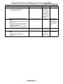
Diagnostic Procedure with Diagnostic Trouble Code (DTC)
LAN SYSTEM (DIAGNOSTICS)
10
11
12
Step
CHECK POWER SUPPLY CIRCUIT.
1) Turn the ignition switch to ON (engine
OFF).
2) Measure the ignition voltage between body
integrated unit connector and chassis ground.
Connector & terminal
(i84) No. 1 (+) — Chassis ground (−):
CHECK HARNESS CONNECTOR BETWEEN
BODY INTEGRATED UNIT AND CHASSIS
GROUND.
1) Turn the ignition switch to OFF.
2) Disconnect the connector from body integrated unit.
3) Measure the harness resistance between
the body integrated unit and chassis ground.
Connector & terminal
(B280) No. 19 — Chassis ground:
CHECK POOR CONTACT IN CONNECTORS.
Check
Yes
Is the voltage more than 10 V? Go to step 11.
No
Repair the open
circuit of harness
between the body
integrated unit and
battery.
Is the resistance more than 1
MΩ?
Repair the poor
contact of harness between the
body integrated
unit and ground.
Go to step 12.
Is there poor contact at control Replace the body
unit ground and Subaru Select integrated unit.
Monitor?
<Ref. to SL-46,
Body Integrated
Unit.>
Repair the poor
contact connector.
CAUTION:
When replacing body integrated unit on the model with immobilizer system, refer to “REGISTRATION
MANUAL FOR IMMOBILIZER”.
LAN(diag)-32
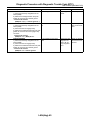
Diagnostic Procedure with Diagnostic Trouble Code (DTC)
LAN SYSTEM (DIAGNOSTICS)
B: DIAGNOSTIC TROUBLE CODE (DTC) IS NOT STORED
DTC DETECTING CONDITION:
Defective combination meter
DIAGNOSIS:
• Freeze frame data in odo/trip meter is not cleared.
• “No trouble code” is displayed on Subaru Select Monitor.
NOTE:
If DTC is not displayed on Subaru Select Monitor, LAN communication System should be OK.
1
2
3
4
Step
Check
CHECK FREEZE FRAME DATA WITH COM- Is the freeze frame data disBINATION METER.
played?
Turn the ignition switch to ON.
CHECK COMBINATION METER.
Is combination meter OK?
Perform the self-diagnosis of combination
meter.
Is the “Yes” displayed?
CHECK BODY INTEGRATED UNIT.
1) Display the current data of ECM using Subaru Select Monitor.
2) Check data of “body integrated unit data
received”.
CHECK BODY INTEGRATED UNIT.
Is the “Yes” displayed?
1) Display the current data of ECM using Subaru Select Monitor.
2) Check data of “body integrated unit counter
update”.
Yes
No
Perform the diag- Go to step 2.
nosis according to
freeze frame data.
Go to step 3.
Replace the combination meter.
<Ref. to IDI-16,
Combination
Meter Assembly.>
Go to step 4.
Replace the body
integrated unit.
<Ref. to SL-46,
Body Integrated
Unit.>
Repair the poor
Replace the body
contact connector. integrated unit.
<Ref. to SL-46,
Body Integrated
Unit.>
C: DTC B0100 INTEG. UNIT SYSTEM ERROR
DTC DETECTING CONDITION:
System error in body integrated unit
TROUBLE SYMPTOM:
• Check light comes on in the combination meter, and displays freeze frame data “Er IU”.
• LAN communication immobilizer function may not be executed normally.
1
Step
CHECK ALL DTCS.
Check
Is DTC concerning ECM displayed?
Yes
Go to step 2.
2
CHECK DTC CONCERNING ECM.
Is output DTC on ECM concerning CAN communication
error?
Replace the body
integrated unit.
<Ref. to SL-46,
Body Integrated
Unit.>
LAN(diag)-33
No
Replace the body
integrated unit.
<Ref. to SL-46,
Body Integrated
Unit.>
Perform the diagnosis according to
DTC concerning
ECM.
Diagnostic Procedure with Diagnostic Trouble Code (DTC)
LAN SYSTEM (DIAGNOSTICS)
D: DTC B0101 BATT P/SUPPLY MALFUNCTION CONT.
DTC DETECTING CONDITION:
BATT power supply control circuit is open or shorted.
TROUBLE SYMPTOM:
No malfunction occurs with back-up power supply function.
NOTE:
When some B0102 BATT p/supply malfunction backup are output at the same time, all function of body integrated unit may not function.
WIRING DIAGRAM:
BATTERY
A:
MAIN SBF-11
i84
BACK-UP
POWER SUPPLY
LR B13
B:
B:
B52
C:
C2
B281
4 5 6 7
1 2 3
8 9 10 11 12 13 14 15 16 17 18 19
27 28
24 25 26
22 23
20 21
B:
A:
B280
1 2 3
4 5
6 7
8 9 10 11 12 13 14 15 16 17 18 19 20
21 22
23 24 25
26 27
28 29 30
B7 LR
WL
C: R168
WL C24
FB-18 No.7
E
MB-29 No.8
SYSTEM CONTROL
POWER SUPPLY
1 2
3 4
5 6
7 8
9 10 11 12 13 14 15 16 17 18 19 20 21 22 23
24 25
26 27 28 29
30 31 32 33
34 35
B52
i84
MICRO COMPUTER
B: B280
BODY INTEGRATED UNIT
6 7 8 9 10 11
1 2 3 4 5
12 13 14 15 16 17 18 19 20 21 22 23 24
C9
BY
C8
C: R168
BY
BY B22
BY A21
C: B281
E
E
REF.TO GND-03
REF.TO GND-02
1 2 3 4
5 6 7 8 9
10 11 12 13 14 15 16 17 18 19 20
LAN00022
LAN(diag)-34
Diagnostic Procedure with Diagnostic Trouble Code (DTC)
LAN SYSTEM (DIAGNOSTICS)
1
2
3
4
Step
CHECK FUSE (No. 7).
1) Turn the ignition switch to OFF.
2) Remove the fuse (No. 7).
Check
Is the fuse blown out?
Yes
No
Replace the fuse Go to step 2.
(No. 7). If the
replaced fuse has
blown out easily,
repair the short circuit in harness
between fuse (No.
7) and body integrated unit.
Is the voltage more than 10 V? Go to step 3.
Repair the harCONTINUITY CHECK OF WIRING HARness for open or
NESS.
shorted circuit
1) Disconnect the connector (B281) from body
between body inteintegrated unit.
grated unit and
2) Measure the voltage between body intefuse.
grated unit connector and chassis ground.
Connector & terminal
(B281) No. 2 (+) — Chassis ground (−):
CHECK POOR CONTACT IN CONNECTORS. Is there poor contact in body
Repair the poor
Go to step 4.
integrated unit connector?
contact connector.
CHECK BODY INTEGRATED UNIT HARIs the same DTC displayed?
Replace the body Temporary poor
NESS.
integrated unit.
contact occurs.
1) Connect all the connectors.
<Ref. to SL-46,
2) Perform the clear memory mode.
Body Integrated
3) Read DTC.
Unit.>
LAN(diag)-35
Diagnostic Procedure with Diagnostic Trouble Code (DTC)
LAN SYSTEM (DIAGNOSTICS)
E: DTC B0102 BATT P/SUPPLY MALFUNCTION CONT.
DTC DETECTING CONDITION:
BATT power backup circuit is open or shorted.
TROUBLE SYMPTOM:
• Engine malfunction indicator light may be illuminates.
• Keyless entry, room light, key illumination does not operate.
• “En IU” may display in combination meter.
NOTE:
When some B0101 BATT p/supply malfunction cont. are output at the same time, all function of body integrated unit may not function.
WIRING DIAGRAM:
BATTERY
A:
MAIN SBF-11
i84
BACK-UP
POWER SUPPLY
LR B13
B:
B:
B52
C:
C2
B281
4 5 6 7
1 2 3
8 9 10 11 12 13 14 15 16 17 18 19
27 28
24 25 26
22 23
20 21
B:
A:
B280
1 2 3
4 5
6 7
8 9 10 11 12 13 14 15 16 17 18 19 20
21 22
23 24 25
26 27
28 29 30
B7 LR
WL
C: R168
WL C24
FB-18 No.7
E
MB-29 No.8
SYSTEM CONTROL
POWER SUPPLY
1 2
3 4
5 6
7 8
9 10 11 12 13 14 15 16 17 18 19 20 21 22 23
24 25
26 27 28 29
30 31 32 33
34 35
B52
i84
MICRO COMPUTER
B: B280
BODY INTEGRATED UNIT
6 7 8 9 10 11
1 2 3 4 5
12 13 14 15 16 17 18 19 20 21 22 23 24
C9
BY
C8
C: R168
BY
BY B22
BY A21
C: B281
E
E
REF.TO GND-03
REF.TO GND-02
1 2 3 4
5 6 7 8 9
10 11 12 13 14 15 16 17 18 19 20
LAN00022
LAN(diag)-36
Diagnostic Procedure with Diagnostic Trouble Code (DTC)
LAN SYSTEM (DIAGNOSTICS)
1
2
3
4
Step
CHECK FUSE (No. 8).
1) Turn the ignition switch to OFF.
2) Remove the fuse (No. 8).
Check
Is the fuse blown out?
Yes
No
Replace the fuse Go to step 2.
(No. 8). If the
replaced fuse has
blown out easily,
repair the short circuit in harness
between fuse (No.
8) and body integrated unit.
Is the voltage more than 10 V? Go to step 3.
Repair the harCONTINUITY CHECK OF WIRING HARness for open or
NESS.
shorted circuit
1) Disconnect the connector (B280) from body
between body inteintegrated unit.
grated unit and
2) Measure the voltage between body intefuse.
grated unit connector and chassis ground.
Connector & terminal
(B280) No. 7 (+) — Chassis ground (−):
CHECK POOR CONTACT IN CONNECTORS. Is there poor contact in body
Repair the poor
Go to step 4.
integrated unit connector?
contact connector.
CHECK BODY INTEGRATED UNIT HARIs the same DTC displayed?
Replace the body Temporary poor
NESS.
integrated unit.
contact occurs.
1) Connect all the connectors.
<Ref. to SL-46,
2) Perform the clear memory mode.
Body Integrated
3) Read DTC.
Unit.>
LAN(diag)-37
Diagnostic Procedure with Diagnostic Trouble Code (DTC)
LAN SYSTEM (DIAGNOSTICS)
F: DTC B0103 IGNITION POWER FAILURE
DTC DETECTING CONDITION:
IGN power supply circuit is open or shorted.
TROUBLE SYMPTOM:
Symptom that illuminating engine malfunction indicator light, “Er HC” high speed CAN error display may be
occurred.
WIRING DIAGRAM:
IGNITION SWITCH
BATTERY
OFF ACC ON
MAIN SBF-11
W
1
B
Y
2
ACC
G
4
IG
E
A:
i84
1 2
3 4
5 6
7 8
9 10 11 12 13 14 15 16 17 18 19 20 21 22 23
24 25
26 27 28 29
30 31 32 33
34 35
A:
IG POWER SUPPLY
FB-37 No.12
YG
GR A8
A1 GR
B52
A24 YG
B:
B1
FB-28 No.31
ACC POWER SUPPLY
B72
B:
1 2 3
4 5
6 7
8 9 10 11 12 13 14 15 16 17 18 19 20
21 22
23 24 25
26 27
28 29 30
C:
A:
B280
B281
i5
4 5 6 7
1 2 3
8 9 10 11 12 13 14 15 16 17 18 19
27 28
24 25 26
22 23
20 21
B:
B52
1 2 3 4 5
6 7 8 9 10 11
12 13 14 15 16 17 18 19 20 21 22 23 24
i84
B: B280
MICRO COMPUTER
BODY INTEGRATED UNIT
C: B281
C8
C9
BY
BY
BY B22
BY A21
A:
i5
1 2 3 4
5 6 7 8 9
10 11 12 13 14 15 16 17 18 19 20
B72
1 2 3
4 5 6
E
E
REF.TO GND-03
REF.TO GND-02
LAN00023
LAN(diag)-38
Diagnostic Procedure with Diagnostic Trouble Code (DTC)
LAN SYSTEM (DIAGNOSTICS)
1
2
3
4
Step
CHECK FUSE (No. 12).
1) Turn the ignition switch to OFF.
2) Remove the fuse (No. 12).
Check
Is the fuse blown out?
Yes
No
Replace the fuse Go to step 2.
(No. 12). If the
replaced fuse has
blown out easily,
repair the short circuit in harness
between fuse (No.
12) and body integrated unit.
Is the voltage more than 10 V? Go to step 3.
Repair the harness for open or
shorted circuit
between body integrated unit and
fuse.
CONTINUITY CHECK OF WIRING HARNESS.
1) Disconnect the connector (i84) from body
integrated unit.
2) Turn the ignition switch to ON.
3) Measure the voltage between body integrated unit connector and chassis ground.
Connector & terminal
(i84) No. 1 (+) — Chassis ground (−):
CHECK POOR CONTACT IN CONNECTOR. Is there poor contact in body
integrated unit connector?
CHECK BODY INTEGRATED UNIT HARIs the same DTC displayed?
NESS.
1) Connect all the connectors.
2) Perform the clear memory mode.
3) Read DTC.
LAN(diag)-39
Repair the poor
Go to step 4.
contact connector.
Replace the body Temporary poor
integrated unit.
contact occurs.
<Ref. to SL-46,
Body Integrated
Unit.>
Diagnostic Procedure with Diagnostic Trouble Code (DTC)
LAN SYSTEM (DIAGNOSTICS)
G: DTC B0104 ACC POWER FAILURE
DTC DETECTING CONDITION:
ACC power supply circuit is open or shorted.
TROUBLE SYMPTOM:
Rear wiper may not operate on ACC.
WIRING DIAGRAM:
IGNITION SWITCH
BATTERY
OFF ACC ON
MAIN SBF-11
W
1
B
Y
2
ACC
G
4
IG
E
A:
i84
1 2
3 4
5 6
7 8
9 10 11 12 13 14 15 16 17 18 19 20 21 22 23
24 25
26 27 28 29
30 31 32 33
34 35
A:
IG POWER SUPPLY
FB-37 No.12
YG
GR A8
A1 GR
B52
A24 YG
B:
B1
FB-28 No.31
ACC POWER SUPPLY
B72
B:
1 2 3
4 5
6 7
8 9 10 11 12 13 14 15 16 17 18 19 20
21 22
23 24 25
26 27
28 29 30
C:
A:
B280
B281
i5
4 5 6 7
1 2 3
8 9 10 11 12 13 14 15 16 17 18 19
27 28
24 25 26
22 23
20 21
B:
B52
1 2 3 4 5
6 7 8 9 10 11
12 13 14 15 16 17 18 19 20 21 22 23 24
i84
B: B280
MICRO COMPUTER
BODY INTEGRATED UNIT
C: B281
C8
C9
BY
BY
BY B22
BY A21
A:
i5
1 2 3 4
5 6 7 8 9
10 11 12 13 14 15 16 17 18 19 20
B72
1 2 3
4 5 6
E
E
REF.TO GND-03
REF.TO GND-02
LAN00023
LAN(diag)-40
Diagnostic Procedure with Diagnostic Trouble Code (DTC)
LAN SYSTEM (DIAGNOSTICS)
1
2
3
4
Step
CHECK FUSE (No. 31).
1) Turn the ignition switch to OFF.
2) Remove the fuse (No. 31).
Check
Is the fuse blown out?
Yes
No
Replace the fuse Go to step 2.
(No. 31). If the
replaced fuse has
blown out easily,
repair the short circuit in harness
between fuse (No.
31) and body integrated unit.
Is the voltage more than 10 V? Go to step 3.
Repair the harness for open or
shorted circuit
between body integrated unit and
fuse.
CONTINUITY CHECK OF WIRING HARNESS.
1) Disconnect the connector (i84) from body
integrated unit.
2) Turn the ignition switch to ON.
3) Measure the voltage between body integrated unit connector and chassis ground.
Connector & terminal
(i84) No. 24 (+) — Chassis ground (−):
CHECK POOR CONTACT IN CONNECTOR. Is there poor contact in body
integrated unit connector?
CHECK BODY INTEGRATED UNIT HARIs DTC displayed?
NESS.
1) Connect all the connectors.
2) Perform the clear memory mode.
3) Read DTC.
LAN(diag)-41
Repair the poor
Go to step 4.
contact connector.
Replace the body Temporary poor
integrated unit.
contact occurs.
<Ref. to SL-46,
Body Integrated
Unit.>
Diagnostic Procedure with Diagnostic Trouble Code (DTC)
LAN SYSTEM (DIAGNOSTICS)
H: DTC B0106 SHIFT LOCK CIRCUIT FAILURE
DTC DETECTING CONDITION:
Shift lock circuit is ground shorted.
TROUBLE SYMPTOM:
Key interlock does not unlock or lock.
WIRING DIAGRAM:
OC :
1 2
WL
GR
YR
FB-3
F/B FUSE No.8
(B)
WB
REF.TO POWER SUPPLY ROUTING
FB-28
FB-37
MB-28
F/B FUSE No.31 F/B FUSE No.12 M/B FUSE No.34
(ACC)
(IG)
(B)
1 2
WC
OC
STOP LIGHT
SWITCH
WC
OC
OC :
B64
WC :
B65
BrW
2 3
B64
WC :
B65
1 2
3 4
F: B159
7
3 4
8 9
F9
1 2
5 6
C1 WB
A1 GR
A24 YR
B:
B280
C:
B281
BODY INTEGRATED UNIT
B116
1 2
3 4
5 6 7 8 9 10
A:
i84
1 2
3 4
5 6
7 8
9 10 11 12 13 14 15 16 17 18 19 20 21 22 23
24 25
26 27 28 29
30 31 32 33
34 35
B6
i84
R
B: B280
: WITHOUT CRUISE CONTROL
WC
: WITH CRUISE CONTROL
1 2 3
4 5
6 7
8 9 10 11 12 13 14 15 16 17 18 19 20
21 22
23 24 25
26 27
28 29 30
3
R
OC
C: B281
SHIFT LOCK
SOLENOID
B
4 5 6 7
1 2 3
8 9 10 11 12 13 14 15 16 17 18 19
27 28
24 25 26
22 23
20 21
4
B116
B
A:
F: B159
C23 BrR
BrR F5
JOINT FUSE BOX
E
REF.TO GND-02
LAN00025
LAN(diag)-42
Diagnostic Procedure with Diagnostic Trouble Code (DTC)
LAN SYSTEM (DIAGNOSTICS)
1
2
3
4
5
Step
CHECK HARNESS.
1) Disconnect the body integrated unit connector (B280).
2) Measure the resistance between body integrated unit connector and chassis ground.
Connector & terminal
(B280) No. 6 — Chassis ground:
CHECK HARNESS.
1) Disconnect the body integrated unit connector (B280).
2) Disconnect the shift lock solenoid connector.
3) Measure the resistance between body integrated unit connector and shift lock solenoid
connector.
Connector & terminal
(B280) No. 6 — (B116) No. 3:
CHECK SHIFT LOCK SOLENOID.
1) Disconnect the shift lock solenoid connector.
2) Measure the internal resistance of shift lock
solenoid.
Connector & terminal
(B116) No. 3 — No. 4:
CHECK GROUND CIRCUIT.
1) Disconnect the shift lock solenoid connector.
2) Measure the resistance between shift lock
solenoid connector and chassis ground.
Connector & terminal
(B116) No. 4 — Chassis ground:
CHECK HARNESS.
1) Disconnect the body integrated unit connector (B280).
2) Measure the resistance between body integrated unit connector (B280) and chassis
ground.
Connector & terminal
(B280) No. 6 — Chassis ground:
Check
Is the resistance 10 — 30 Ω?
Yes
Go to step 5.
No
Go to step 2.
Is the resistance less than 10
Ω?
Go to step 3.
Repair or replace
the open or short
circuit of harness.
Is the resistance 10 — 30 Ω?
Go to step 4.
Replace the shift
lock solenoid.
Is the resistance less than 10
Ω?
Temporary poor
contact occurs.
Check the connection of each terminals, and then
repair them if necessary.
Replace the body
integrated unit.
<Ref. to SL-46,
Body Integrated
Unit.>
Replace the body
integrated unit.
<Ref. to SL-46,
Body Integrated
Unit.>
Is the resistance more than 1
MΩ?
LAN(diag)-43
Repair or replace
the short circuit of
harness.
Diagnostic Procedure with Diagnostic Trouble Code (DTC)
LAN SYSTEM (DIAGNOSTICS)
I:
DTC B0107 R FOG LAMP CIRCUIT FAILURE
DTC DETECTING CONDITION:
Rear fog input/output circuits are ground shorted.
TROUBLE SYMPTOM:
• Rear fog light does not come on or go off.
• Indicator in the combination meter may not be goes off.
WIRING DIAGRAM:
REF.TO POWER SUPPLY ROUTING
B71
LG
V
28
FB-14
F/B FUSE No.16
(B)
26
FB-2
F/B FUSE No.1
(B)
1
9
2
10
3 4 5 6
11 12 13 14 15
7
16
8
17
B: B280
REAR FOG
LIGHT RELAY
1 2 3
4 5
6 7
8 9 10 11 12 13 14 15 16 17 18 19 20
23 24 25
26 27
28 29 30
21 22
27
25
B225
B13
C: B281
4 5 6 7
1 2 3
8 9 10 11 12 13 14 15 16 17 18 19
27 28
22 23
24 25 26
20 21
BODY INTEGRATED UNIT
REAR FOG LIGHT
C4
B: B280
C: B281
13
B225
REAR FOG
LIGHT SWITCH
ON
OFF
2
3
4
5
6
7
8
9
10
11 12
13
14
15 16
17
18
19 20
21
22
23 24
25
26
27 28
29
30
31 32
33
34
35 36
37
38
39 40
B
16
B71
1
E
REF. TO GROUND DISTRIBUTION
[GND-02]
LAN00026
LAN(diag)-44
Diagnostic Procedure with Diagnostic Trouble Code (DTC)
LAN SYSTEM (DIAGNOSTICS)
1
2
3
Step
CHECK HARNESS.
1) Disconnect the body integrated unit connector (B280).
2) Measure the voltage between body integrated unit connector and chassis ground.
Connector & terminal
(B280) No. 13 (+) — Chassis ground (−):
CHECK HARNESS.
1) Disconnect the body integrated unit connector (B280).
2) Disconnect the rear fog light relay.
3) Measure the resistance between body integrated unit connector and rear fog light relay
connector.
Connector & terminal
(B280) No. 13 — (B225) No. 27:
CHECK HARNESS.
1) Disconnect the body integrated unit connector (B280).
2) Disconnect the rear fog light relay.
3) Measure the resistance between body integrated unit connector and chassis ground.
Connector & terminal
(B280) No. 13 — Chassis ground:
Check
Is the voltage 10 — 13 V?
Yes
Temporary poor
contact.
No
Go to step 2.
Is the resistance less than 1
Ω?
Go to step 3.
Repair the open or
short circuit of harness.
Is the resistance more than 1
MΩ?
Replace the body
integrated unit.
<Ref. to SL-46,
Body Integrated
Unit.>
Repair or replace
the short circuit of
harness.
LAN(diag)-45
Diagnostic Procedure with Diagnostic Trouble Code (DTC)
LAN SYSTEM (DIAGNOSTICS)
J: DTC B0201 CAN-HS COUNTER ABNORMAL
DTC DETECTING CONDITION:
High speed CAN communication of body integrated unit which monitoring the error data and non-received
data are faulty.
TROUBLE SYMPTOM:
• “Er HC” is displayed in odo/trip meter.
• Engine malfunction indicator light illuminates.
1
2
3
4
5
6
Step
CHECK HARNESS.
1) Disconnect the body integrated unit connector (B280).
2) Measure the resistance between harness
connector terminals.
Connector & terminal
(B280) No. 20 — No. 30:
CHECK HARNESS.
1) Disconnect the body integrated unit connector (B280).
2) Measure the resistance between harness
connector terminals.
Connector & terminal
(B280) No. 20 — No. 30:
CHECK HARNESS.
1) Disconnect the body integrated unit connector (B280).
2) Measure the input voltage between harness connector and chassis ground while turning the ignition switch to ON.
Connector & terminal
(B280) No. 20 (+) — Chassis ground (−):
(B280) No. 30 (+) — Chassis ground (−):
CHECK HARNESS.
1) Disconnect the body integrated unit connector (B280).
2) Measure the resistance between harness
connector and chassis ground.
Connector & terminal
(B280) No. 20 — Chassis ground:
(B280) No. 30 — Chassis ground:
CHECK BODY INTEGRATED UNIT.
Read the data of “body integrated unit data
received” on ECM data display using Subaru
Select Monitor.
Check
Is the resistance 55 — 65 Ω?
Yes
Temporary poor
contact occurs.
No
Go to step 2.
Is the resistance more than 30 Repair or replace Go to step 3.
MΩ?
the open circuit of
harness.
Is the voltage more than 6 V?
Repair or replace Go to step 4.
the short circuit of
harness.
Is the resistance less than 10
Ω?
Repair or replace Go to step 5.
the short circuit of
harness.
Is the “Yes” displayed?
Go to step 6.
CHECK BODY INTEGRATED UNIT.
Is the “Yes” displayed?
Read the data of “body integrated unit counter
update” on ECM data display using Subaru
Select Monitor.
LAN(diag)-46
Replace the body
integrated unit.
<Ref. to SL-46,
Body Integrated
Unit.>
Temporary poor
Replace the body
contact occurs.
integrated unit.
Check the con<Ref. to SL-46,
nected condition of Body Integrated
connector, read
Unit.>
the DTC again to
make sure that the
DTC is not output.
Diagnostic Procedure with Diagnostic Trouble Code (DTC)
LAN SYSTEM (DIAGNOSTICS)
K: DTC B0202 CAN-HS BUS OFF
DTC DETECTING CONDITION:
• Locate the unit or CAN line which trouble occurs, and repair and replace it.
• Not received data and error data may be detected at the same time.
TROUBLE SYMPTOM:
“Er HC” is displayed in odo/trip meter.
WIRING DIAGRAM:
B: B280
ECM
VDCCM & H/U
13
B30
B20
D26 C14
D18 C13
D: B137
*1
*2
B310
BODY INTEGRATED
UNIT
29
C: B136
STEERING ANGLE
SENSOR
TWISTED WIRE
2
1
3
B231
ABS
VDC
4AT
1 2 3 4
L
L
L
L
SOHC RHD MODEL;
(KA) RHD MODEL;
LHD MODEL;
(KS) LHD MODEL
*2
: EXCEPT FOR 2.0 L SOHC
RHD AND 2.5 L (KA) RHD
MODEL;
2.5 L (EC, K4) LHD MODEL;
3.0 L LHD MODEL
BY
B54
ABSCM & H/U
REF. TO GROUND DISTRIBUTION
[GND-02]
TCM
B231
: 2.0
2.5
2.0
2.5
E
B301
A:
*1
11
26
A12 A3
5AT
A3 A4
ABS
VDC
5AT A:
1 2 3 4
10 11 12 13
19 20 21
D: B137
1 2 3 4 5 6 7
8 9 10 11 12 13 14 15 16 17
18 19 20 21 22 23
24 25
26 27
28 29
30 31
4AT A:
B54
5 6
14 15
7
16
22
8
17
23
9
18
24
B: B280
B54
4 5
6 7
1 2 3
8 9 10 11 12 13 14 15 16 17 18 19 20
23 24 25
26 27
28 29 30
21 22
1 2
3 4 5 6 7
8 9 10 11 12 13 14 15 16
17 18 19 20 21
22 23 24
B310
C: B136
1 2 3 4
7 8 9 10 11 12 13
17 18 19 20 21 22 23 24
28 29 30
31 32
5 6
14 15 16
25 26 27
33 34 35
B301
5
6
7
8
9
10
1 2 3 4
11 12 13 14 15 16 17 18 19 20 21 22 23 24 25 26
27 28 29 30 31 32 33 34 35 36 37 38 39 40 41 42
12
13
14
15
1 2 3 4 5 6 7 8 9 10 11
16 17 18 19 20 21 22 23 24 25 26
LAN00113
LAN(diag)-47
Diagnostic Procedure with Diagnostic Trouble Code (DTC)
LAN SYSTEM (DIAGNOSTICS)
1
2
3
4
5
6
7
Step
CHECK TCM.
1) Disconnect the TCM connector (B54).
2) Perform the clear memory of body integrated unit. <Ref. to LAN(diag)-20, CLEAR
MEMORY MODE, OPERATION, Subaru
Select Monitor.>
3) Read DTC of body integrated unit.
CHECK STEERING ANGLE SENSOR.
1) Disconnect the steering angle sensor connector (B231).
2) Perform the clear memory mode of body
integrated unit. <Ref. to LAN(diag)-20, CLEAR
MEMORY MODE, OPERATION, Subaru
Select Monitor.>
3) Read DTC of body integrated unit.
CHECK BODY INTEGRATED UNIT.
1) Disconnect the body integrated unit connector (B280).
2) Read the data between VDC/ABSCM and
ECM.
Check item:
• Engine speed
• Average front wheel speed (value on constant driving)
CHECK HARNESS.
1) Disconnect the body integrated unit connector (B280).
2) Measure the resistance between harness
connector terminals.
Connector & terminal
(B280) No. 20 — No. 30:
CHECK HARNESS.
1) Disconnect the body integrated unit connector (B280).
2) Measure the resistance between harness
connector terminals.
Connector & terminal
(B280) No. 20 — No. 30:
CHECK HARNESS.
1) Disconnect the harness connector of body
integrated unit.
2) Measure the resistance between harness
connector terminals.
Connector & terminal
(B280) No. 20 — No. 30:
CHECK HARNESS.
1) Disconnect the VDC/ABSCM connector
(ABS:B301, VDC:310).
2) Measure the resistance between harness
connector terminals.
Connector & terminal
ABS
(B301) No. 11 — No. 26:
VDC
(B310) No. 13 — No. 29:
Check
Is DTC (B0202) displayed?
Yes
Go to step 2.
No
Replace the TCM.
<Ref. to 4AT-140,
Transmission Control Device.> <Ref.
to 5AT-61, Transmission Control
Module (TCM).>
Replace the steering angle sensor.
<Ref. to VDC-16,
REPLACEMENT,
Steering Angle
Sensor.>
Is DTC (B0202) displayed?
Go to step 3.
Engine speed, front wheel
speed is correctly communicated. (Appears same value)
Replace the body
integrated unit.
<Ref. to SL-46,
Body Integrated
Unit.>
Go to step 4.
Is the resistance 55 — 65 Ω?
Go to step 10.
Go to step 5.
Is the resistance 115 — 125
Ω?
Go to step 7.
Go to step 6.
Is the resistance more than 30 Open harness on Go to step 7.
MΩ?
related line of body
integrated unit.
Repair or replace
the open circuit of
harness.
Is the resistance 115 — 125
Ω?
LAN(diag)-48
Go to step 8.
Go to step 9.
Diagnostic Procedure with Diagnostic Trouble Code (DTC)
LAN SYSTEM (DIAGNOSTICS)
8
Step
CHECK VDC/ABSCM.
1) Disconnect the VDC/ABSCM connector
(ABS:B301, VDC:310).
2) Measure the resistance between VDC/
ABSCM terminals.
Connector & terminal
ABS
(B301) No. 11 — No. 26:
VDC
(B310) No. 13 — No. 29:
Check
Is the resistance 115 — 125
Ω?
9
CHECK ECM.
Is the resistance 115 — 125
1) Disconnect the ECM connector (*1: B136, Ω?
*2: B137).
2) Measure the resistance between ECM connector terminals.
Connector & terminal
*1: 2.0 L SOHC RHD model, 2.5 L (KA)
RHD model, 2.0 L LHD model, 2.5 L (KS)
LHD model
(B136) No. 13 — No. 14:
*2: Except for 2.0 L SOHC RHD and 2.5 L
(KA) RHD model, 2.5 L (EC, K4) LHD
model, 3.0 L LHD model
(B137) No. 18 — No. 26:
10
CHECK HARNESS.
1) Disconnect the body integrated unit connector (B280).
2) Measure the resistance between body integrated unit connector and chassis ground.
Connector & terminal
(B280) No. 20 — Chassis ground:
(B280) No. 30 — Chassis ground:
CHECK HARNESS.
1) Disconnect the body integrated unit connector (B280).
2) Measure the voltage between body integrated unit connector and chassis ground.
Connector & terminal
(B280) No. 20 (+) — Chassis ground (−):
(B280) No. 30 (+) — Chassis ground (−):
CHECK DTC.
Read the DTC of ECM using Subaru Select
Monitor. <Ref. to EN(H4SO 2.0)(diag)-25,
READ DIAGNOSTIC TROUBLE CODE (DTC)
FOR ENGINE (NORMAL MODE), OPERATION, Subaru Select Monitor.> <Ref. to
EN(H4DOTC)(diag)-21, READ DIAGNOSTIC
TROUBLE CODE (DTC) FOR ENGINE (NORMAL MODE), OPERATION, Subaru Select
Monitor.>
11
12
Is the resistance less than 10
Ω? (Ground)
Yes
Go to step 9.
No
Open harness in
end resistance of
VDC/ABSCM.
Replace the VDC/
ABSCM. <Ref. to
ABS-6, ABS Control Module and
Hydraulic Control
Unit (ABSCM&H/
U).> <Ref. to VDC7, VDC Control
Module & Hydraulic Control Unit
(VDCCM&H/U).>
Repair or replace Open harness in
the open circuit of end resistance of
harness connec- ECM. Replace the
tor.
ECM. <Ref. to
FU(H4SO 2.0)-34,
Engine Control
Module (ECM).>
<Ref. to FU(H4SO
2.5)-36, Engine
Control Module
(ECM).> <Ref. to
FU(H4DOTC)-35,
Engine Control
Module (ECM).>
<Ref. to
FU(H6DO)-34,
Engine Control
Module (ECM).>
Repair or replace Go to step 11.
the ground short
circuit of the harness.
Is the voltage more than 6 V?
(Power)
Repair or replace Go to step 12.
the short circuit of
harness.
Is DTC other than “CAN communication” displayed?
Perform the diag- Go to step 13.
nosis according to
DTC.
LAN(diag)-49
Diagnostic Procedure with Diagnostic Trouble Code (DTC)
LAN SYSTEM (DIAGNOSTICS)
13
14
Step
CHECK DTC.
Read the DTC of VDC/ABSCM using Subaru
Select Monitor. <Ref. to ABS(diag)-15, READ
DIAGNOSTIC TROUBLE CODE (DTC),
OPERATION, Subaru Select Monitor.> <Ref.
to VDC(diag)-16, READ DIAGNOSTIC TROUBLE CODE (DTC), OPERATION, Subaru
Select Monitor.>
CHECK DTC.
Read the DTC of TCM using Subaru Select
Monitor. <Ref. to 4AT(diag)-17, READ DIAGNOSTIC TROUBLE CODE (DTC), OPERATION, Subaru Select Monitor.> <Ref. to
5AT(diag)-16, READ DIAGNOSTIC TROUBLE CODE (DTC), OPERATION, Subaru
Select Monitor.>
Check
Is DTC other than “CAN communication” displayed?
Yes
No
Perform the diag- Go to step 14.
nosis according to
DTC.
Is DTC other than “CAN communication” displayed?
Perform the diag- Replace the body
nosis according to integrated unit.
DTC.
<Ref. to SL-46,
Body Integrated
Unit.>
LAN(diag)-50
Diagnostic Procedure with Diagnostic Trouble Code (DTC)
LAN SYSTEM (DIAGNOSTICS)
L: DTC B0211 CAN-HS ECM DATA ABNORMAL
DTC DETECTING CONDITION:
Defective data from ECM.
TROUBLE SYMPTOM:
“Er HC” or “Er EG” is displayed in odo/trip meter.
WIRING DIAGRAM:
B: B280
C: B136
ECM
B20
D26 C14
TWISTED WIRE
*1
*2
D18 C13
D: B137
B30
BODY INTEGRATED
UNIT
ABSCM & H/U
VDCCM & H/U
*1
: 2.0
2.5
2.0
2.5
L
L
L
L
SOHC RHD MODEL;
(KA) RHD MODEL;
LHD MODEL;
(KS) LHD MODEL
*2
: EXCEPT FOR 2.0 L SOHC
RHD AND 2.5 L (KA) RHD
MODEL;
2.5 L (EC, K4) LHD MODEL;
3.0 L LHD MODEL
TCM
B: B280
4 5
6 7
1 2 3
8 9 10 11 12 13 14 15 16 17 18 19 20
23 24 25
26 27
28 29 30
21 22
C: B136
1 2 3 4
7 8 9 10 11 12 13
17 18 19 20 21 22 23 24
28 29 30
31 32
D: B137
5 6
14 15 16
25 26 27
33 34 35
1 2 3 4 5 6 7
8 9 10 11 12 13 14 15 16 17
18 19 20 21 22 23
24 25
28 29
30 31
26 27
LAN00114
LAN(diag)-51
Diagnostic Procedure with Diagnostic Trouble Code (DTC)
LAN SYSTEM (DIAGNOSTICS)
1
Step
CHECK ECM.
Read the DTC of ECM using Subaru Select
Monitor.
Check
Is DTC other than “CAN communication” displayed?
LAN(diag)-52
Yes
No
Perform the diag- Replace the ECM.
nosis according to <Ref. to FU(H4SO
DTC.
2.0)-34, Engine
Control Module
(ECM).> <Ref. to
FU(H4SO 2.5)-36,
Engine Control
Module (ECM).>
<Ref. to
FU(H4DOTC)-35,
Engine Control
Module (ECM).>
<Ref. to
FU(H6DO)-34,
Engine Control
Module (ECM).>
Diagnostic Procedure with Diagnostic Trouble Code (DTC)
LAN SYSTEM (DIAGNOSTICS)
M: DTC B0212 CAN-HS TCM DATA ABNORMAL
DTC DETECTING CONDITION:
TCM error, or harness between the main harness splice and TCM is open or short, the connector is not connected securely and the terminal has poor caulking.
TROUBLE SYMPTOM:
• SPORT indicator light blinks.
• “Er HC” or “Er tC” is displayed in odo/trip meter.
WIRING DIAGRAM:
B: B280
B30
B20
BODY INTEGRATED
UNIT
ABSCM & H/U
VDCCM & H/U
4AT
A3 A4
5AT
A:
A12 A3
ECM
B54
TCM
B: B280
4 5
6 7
1 2 3
8 9 10 11 12 13 14 15 16 17 18 19 20
21 22
23 24 25
26 27
28 29 30
5AT A:
B54
1 2 3 4
10 11 12 13
19 20 21
5 6
14 15
4AT A:
7
16
22
8
17
23
9
18
24
B54
1 2
3 4 5 6 7
8 9 10 11 12 13 14 15 16
17 18 19 20 21
22 23 24
LAN00029
1
Step
CHECK TCM.
Read the DTC of TCM using Subaru Select
Monitor. <Ref. to 4AT(diag)-17, READ DIAGNOSTIC TROUBLE CODE (DTC), OPERATION, Subaru Select Monitor.> <Ref. to
5AT(diag)-16, READ DIAGNOSTIC TROUBLE CODE (DTC), OPERATION, Subaru
Select Monitor.>
Check
Is DTC other than “CAN communication” displayed?
LAN(diag)-53
Yes
No
Perform the diag- Replace the TCM.
nosis according to <Ref. to 4AT-65,
DTC.
Transmission Control Module
(TCM).> <Ref. to
5AT-61, Transmission Control Module (TCM).>
Diagnostic Procedure with Diagnostic Trouble Code (DTC)
LAN SYSTEM (DIAGNOSTICS)
N: DTC B0213 CAN-HS VDC/ABS DATA ABNORMAL
DTC DETECTING CONDITION:
VDC/ABSCM body error, or harness between the main harness splice and TCM is open or short, the connector is not connected securely and the terminal has poor caulking.
TROUBLE SYMPTOM:
• ABS warning light and VDC warning light come on.
• “Er HC” or “Er Ab” is displayed in odo/trip meter.
WIRING DIAGRAM:
B310
B: B280
29
13
VDCCM & H/U
B30
B20
BODY INTEGRATED
UNIT
STEERING ANGLE
SENSOR
2
1
3
B231
ABS
VDC
VDC
11
26
BY
ABS
ECM
E
B301
ABSCM & H/U
B: B280
4 5
6 7
1 2 3
8 9 10 11 12 13 14 15 16 17 18 19 20
21 22
23 24 25
26 27
28 29 30
REF. TO GROUND DISTRIBUTION
[GND-02]
B310
B301
10
5
6
7
8
9
1 2 3 4
11 12 13 14 15 16 17 18 19 20 21 22 23 24 25 26
27 28 29 30 31 32 33 34 35 36 37 38 39 40 41 42
12
13
14
15
1 2 3 4 5 6 7 8 9 10 11
16 17 18 19 20 21 22 23 24 25 26
B231
1 2 3 4
LAN00030
LAN(diag)-54
Diagnostic Procedure with Diagnostic Trouble Code (DTC)
LAN SYSTEM (DIAGNOSTICS)
1
Step
CHECK VDC/ABSCM.
Read the DTC of VDC/ABSCM using Subaru
Select Monitor.
Check
Is DTC other than “CAN communication” displayed?
LAN(diag)-55
Yes
No
Perform the diag- Replace the VDC/
nosis according to ABSCM. <Ref. to
DTC.
ABS-6, ABS Control Module and
Hydraulic Control
Unit (ABSCM&H/
U).> <Ref. to VDC7, VDC Control
Module & Hydraulic Control Unit
(VDCCM&H/U).>
Diagnostic Procedure with Diagnostic Trouble Code (DTC)
LAN SYSTEM (DIAGNOSTICS)
O: DTC B0221 CAN-HS ECM NO-RECEIVE DATA
DTC DETECTING CONDITION:
Defective ECM. (If error is in the main harness, Diagnostic Trouble Code (DTC) P0600 High-speed CAN circuit is input simultaneously.)
TROUBLE SYMPTOM:
• Engine malfunction indicator light illuminates.
• “Er HC” is displayed in odo/trip meter.
WIRING DIAGRAM:
B: B280
C: B136
ECM
B20
D26 C14
TWISTED WIRE
*1
*2
D18 C13
D: B137
B30
BODY INTEGRATED
UNIT
ABSCM & H/U
VDCCM & H/U
*1
: 2.0
2.5
2.0
2.5
L
L
L
L
SOHC RHD MODEL;
(KA) RHD MODEL;
LHD MODEL;
(KS) LHD MODEL
*2
: EXCEPT FOR 2.0 L SOHC
RHD AND 2.5 L (KA) RHD
MODEL;
2.5 L (EC, K4) LHD MODEL;
3.0 L LHD MODEL
TCM
B: B280
4 5
6 7
1 2 3
8 9 10 11 12 13 14 15 16 17 18 19 20
21 22
23 24 25
26 27
28 29 30
C: B136
1 2 3 4
7 8 9 10 11 12 13
17 18 19 20 21 22 23 24
28 29 30
31 32
D: B137
5 6
14 15 16
25 26 27
33 34 35
1 2 3 4 5 6 7
8 9 10 11 12 13 14 15 16 17
18 19 20 21 22 23
24 25
28 29
30 31
26 27
LAN00114
LAN(diag)-56
Diagnostic Procedure with Diagnostic Trouble Code (DTC)
LAN SYSTEM (DIAGNOSTICS)
1
2
Step
CHECK HARNESS.
1) Disconnect the body integrated unit connector (B280).
2) Measure the resistance between harness
connectors.
Connector & terminal
(B280) No. 20 — No. 30:
Check
Is the resistance 55 — 65 Ω?
(Standard 60 Ω)
CHECK HARNESS.
1) Disconnect the body integrated unit connector (B280).
2) Measure the resistance between harness
connectors.
Connector & terminal
(B280) No. 20 — No. 30:
Is the resistance 115 — 125
Ω? (End resistance or main
line is open)
LAN(diag)-57
Yes
No
Read the DTC of Go to step 2.
ECM. Perform the
diagnosis according to DTC. <Ref.
to EN(H4SO
2.0)(diag)-25,
READ DIAGNOSTIC TROUBLE
CODE (DTC) FOR
ENGINE (NORMAL MODE),
OPERATION,
Subaru Select
Monitor.> <Ref. to
EN(H4SO
2.5)(diag)-26,
READ DIAGNOSTIC TROUBLE
CODE (DTC) FOR
ENGINE (NORMAL MODE),
OPERATION,
Subaru Select
Monitor.> <Ref. to
EN(H4DOTC)(diag
)-21, READ DIAGNOSTIC TROUBLE CODE (DTC)
FOR ENGINE
(NORMAL
MODE), OPERATION, Subaru
Select Monitor.>
<Ref. to
EN(H6DO)(diag)25, READ DIAGNOSTIC TROUBLE CODE (DTC)
FOR ENGINE
(NORMAL
MODE), OPERATION, Subaru
Select Monitor.>
Go to step 3.
Related line of
body integrated
unit is open when
∞ Ω. Repair or
replace the open
circuit of harness.
Diagnostic Procedure with Diagnostic Trouble Code (DTC)
LAN SYSTEM (DIAGNOSTICS)
3
4
Step
CHECK HARNESS.
1) Disconnect the ECM connector (*1: B136,
*2: B137).
2) Measure the resistance between harness
connector terminals.
Connector & terminal
*1: 2.0 L SOHC RHD model, 2.5 L (KA)
RHD model, 2.0 L LHD model, 2.5 L (KS)
LHD model
(B136) No. 13 — No. 14:
*2: Except for 2.0 L SOHC RHD and 2.5 L
(KA) RHD model, 2.5 L (EC, K4) LHD
model, 3.0 L LHD model
(B137) No. 18 — No. 26:
CHECK ECM.
1) Disconnect the ECM connector (*1: B136,
*2: B137).
2) Measure the resistance between ECM connector terminals.
Connector & terminal
*1: 2.0 L SOHC RHD model, 2.5 L (KA)
RHD model, 2.0 L LHD model, 2.5 L (KS)
LHD model
(B136) No. 13 — No. 14:
*2: Except for 2.0 L SOHC RHD and 2.5 L
(KA) RHD model, 2.5 L (EC, K4) LHD
model, 3.0 L LHD model
(B137) No. 18 — No. 26:
Check
Is the resistance 115 — 125
Ω? (End resistance standard
120 Ω)
Yes
Go to step 4.
No
Go to step 5.
Is the resistance 115 — 125
Ω?
Read the DTC of
ECM. Perform the
diagnosis according to DTC. <Ref.
to EN(H4SO
2.0)(diag)-25,
READ DIAGNOSTIC TROUBLE
CODE (DTC) FOR
ENGINE (NORMAL MODE),
OPERATION,
Subaru Select
Monitor.> <Ref. to
EN(H4SO
2.5)(diag)-26,
READ DIAGNOSTIC TROUBLE
CODE (DTC) FOR
ENGINE (NORMAL MODE),
OPERATION,
Subaru Select
Monitor.> <Ref. to
EN(H4DOTC)(diag
)-21, READ DIAGNOSTIC TROUBLE CODE (DTC)
FOR ENGINE
(NORMAL
MODE), OPERATION, Subaru
Select Monitor.>
<Ref. to
EN(H6DO)(diag)25, READ DIAGNOSTIC TROUBLE CODE (DTC)
FOR ENGINE
(NORMAL
MODE), OPERATION, Subaru
Select Monitor.>
End resistance is
open. Replace the
ECM. <Ref. to
FU(H4SO 2.0)-34,
Engine Control
Module (ECM).>
<Ref. to FU(H4SO
2.5)-36, Engine
Control Module
(ECM).> <Ref. to
FU(H4DOTC)-35,
Engine Control
Module (ECM).>
<Ref. to
FU(H6DO)-34,
Engine Control
Module (ECM).>
LAN(diag)-58
Diagnostic Procedure with Diagnostic Trouble Code (DTC)
LAN SYSTEM (DIAGNOSTICS)
5
6
Step
Check
CHECK HARNESS.
Is the resistance less than 10
1) Disconnect the ECM connector (*1: B136, Ω?
*2: B137).
2) Measure the resistance between harness
connector and chassis ground.
Connector & terminal
*1: 2.0 L SOHC RHD model, 2.5 L (KA)
RHD model, 2.0 L LHD model, 2.5 L (KS)
LHD model
(B136) No. 13 — Chassis ground:
(B136) No. 14 — Chassis ground:
*2: Except for 2.0 L SOHC RHD and 2.5 L
(KA) RHD model, 2.5 L (EC, K4) LHD
model, 3.0 L LHD model
(B137) No. 18 — Chassis ground:
(B137) No. 26 — Chassis ground:
Is the voltage more than 6 V?
CHECK HARNESS.
1) Disconnect the body integrated unit connector (B280), ECM connector (*1: B136, *2:
B137), TCM connector (B54), ABS (B301)/
VDC (B310) CM connector.
2) Measure the input voltage between harness connector and chassis ground while turning the ignition switch to ON.
Connector & terminal
(B280) No. 20 (+) — Chassis ground (−):
(B280) No. 30 (+) — Chassis ground (−):
LAN(diag)-59
Yes
No
Repair or replace Go to step 6.
the short circuit of
harness.
Repair or replace Read the DTC of
the short circuit of ECM. Perform the
harness.
diagnosis according to DTC. <Ref.
to EN(H4SO
2.0)(diag)-25,
READ DIAGNOSTIC TROUBLE
CODE (DTC) FOR
ENGINE (NORMAL MODE),
OPERATION,
Subaru Select
Monitor.> <Ref. to
EN(H4SO
2.5)(diag)-26,
READ DIAGNOSTIC TROUBLE
CODE (DTC) FOR
ENGINE (NORMAL MODE),
OPERATION,
Subaru Select
Monitor.> <Ref. to
EN(H4DOTC)(diag
)-21, READ DIAGNOSTIC TROUBLE CODE (DTC)
FOR ENGINE
(NORMAL
MODE), OPERATION, Subaru
Select Monitor.>
<Ref. to
EN(H6DO)(diag)25, READ DIAGNOSTIC TROUBLE CODE (DTC)
FOR ENGINE
(NORMAL
MODE), OPERATION, Subaru
Select Monitor.>
Diagnostic Procedure with Diagnostic Trouble Code (DTC)
LAN SYSTEM (DIAGNOSTICS)
P: DTC B0222 CAN-HS TCM NO-RECEIVE DATA
DTC DETECTING CONDITION:
TCM error, or harness between the main harness splice and TCM is open or short, the connector is not connected securely and the terminal has poor caulking.
TROUBLE SYMPTOM:
• Engine malfunction indicator light illuminates.
• “Er HC” is displayed in odo/trip meter.
WIRING DIAGRAM:
B: B280
B30
B20
BODY INTEGRATED
UNIT
ABSCM & H/U
VDCCM & H/U
4AT
A3 A4
5AT
A:
A12 A3
ECM
B54
TCM
B: B280
4 5
6 7
1 2 3
8 9 10 11 12 13 14 15 16 17 18 19 20
21 22
23 24 25
26 27
28 29 30
5AT A:
B54
1 2 3 4
10 11 12 13
19 20 21
5 6
14 15
4AT A:
7
16
22
8
17
23
9
18
24
B54
1 2
3 4 5 6 7
8 9 10 11 12 13 14 15 16
17 18 19 20 21
22 23 24
LAN00029
LAN(diag)-60
Diagnostic Procedure with Diagnostic Trouble Code (DTC)
LAN SYSTEM (DIAGNOSTICS)
1
2
Step
CHECK HARNESS.
1) Disconnect the TCM connector (B54)
2) Measure the resistance between harness
connector terminals.
Connector & terminal
4AT MODEL
(B54) No. 3 — No. 12:
5AT MODEL
(B54) No. 3 — No. 4:
CHECK TCM.
Read the DTC of TCM using Subaru Select
Monitor. <Ref. to 4AT(diag)-17, READ DIAGNOSTIC TROUBLE CODE (DTC), OPERATION, Subaru Select Monitor.> <Ref. to
5AT(diag)-16, READ DIAGNOSTIC TROUBLE CODE (DTC), OPERATION, Subaru
Select Monitor.>
Check
Is the resistance ∞ Ω?
Yes
No
Open harness in Go to step 2.
related lines of
TCM. Repair or
replace the open
circuit of harness.
Is DTC other than “CAN communication” displayed?
Perform the diag- Replace the TCM.
nosis according to <Ref. to 4AT-65,
DTC.
Transmission Control Module
(TCM).> <Ref. to
5AT-61, Transmission Control Module (TCM).>
LAN(diag)-61
Diagnostic Procedure with Diagnostic Trouble Code (DTC)
LAN SYSTEM (DIAGNOSTICS)
Q: DTC B0223 CAN-HS VDC/ABS NO-RECEIVE DATA
DTC DETECTING CONDITION:
Defective VDC/ABSCM. (If error is in the main harness, DTC P0600 High-speed CAN circuit is input at the
same time.)
TROUBLE SYMPTOM:
• ABS warning light and VDC warning light come on.
• “Er HC” is displayed in odo/trip meter.
WIRING DIAGRAM:
B310
B: B280
29
13
VDCCM & H/U
B30
B20
BODY INTEGRATED
UNIT
STEERING ANGLE
SENSOR
2
1
3
B231
ABS
VDC
VDC
11
26
BY
ABS
ECM
E
B301
ABSCM & H/U
B: B280
4 5
6 7
1 2 3
8 9 10 11 12 13 14 15 16 17 18 19 20
21 22
23 24 25
26 27
28 29 30
REF. TO GROUND DISTRIBUTION
[GND-02]
B310
B301
10
5
6
7
8
9
1 2 3 4
11 12 13 14 15 16 17 18 19 20 21 22 23 24 25 26
27 28 29 30 31 32 33 34 35 36 37 38 39 40 41 42
12
13
14
15
1 2 3 4 5 6 7 8 9 10 11
16 17 18 19 20 21 22 23 24 25 26
B231
1 2 3 4
LAN00030
LAN(diag)-62
Diagnostic Procedure with Diagnostic Trouble Code (DTC)
LAN SYSTEM (DIAGNOSTICS)
1
2
3
4
5
6
Step
CHECK HARNESS.
1) Disconnect the harness connector of body
integrated unit.
2) Measure the resistance between harness
connector terminals.
Connector & terminal
(B280) No. 20 — No. 30:
CHECK HARNESS.
1) Disconnect the harness connector of body
integrated unit.
2) Measure the resistance between harness
connector terminals.
Connector & terminal
(B280) No. 20 — No. 30:
CHECK HARNESS.
1) Disconnect the harness connector of body
integrated unit.
2) Measure the resistance between the harness connector terminal and chassis ground.
Connector & terminal
(B280) No. 20 — Chassis ground:
(B280) No. 30 — Chassis ground:
CHECK HARNESS.
1) Disconnect the harness connector of body
integrated unit.
2) Measure the voltage between the harness
connector terminal and chassis ground. (Ignition switch ON)
Connector & terminal
(B280) No. 20 (+) — Chassis ground (−):
(B280) No. 30 (+) — Chassis ground (−):
CHECK END RESISTANCE.
1) Disconnect the VDC/ABSCM harness connector.
2) Measure the resistance between VDC/
ABSCM connector terminals.
Connector & terminal
ABS
(B301) No. 11 — No. 26:
VDC
(B310) No. 13 — No. 29:
CHECK HARNESS.
1) Disconnect the body integrated unit connector (B280) and VDC/ABSCM connector
(ABS:B301, VDC:310).
2) Measure the resistance between harness
connector terminals.
Connector & terminal
ABS
(B301) No. 11 — (B280) No. 30:
(B301) No. 26 — (B280) No. 20:
VDC
(B310) No. 13 — (B280) No. 20:
(B310) No. 29 — (B280) No. 30:
Check
Is the resistance 55 — 65 Ω?
Yes
No
Read the DTC of Go to step 2.
VDC/ABSCM, and
perform the diagnosis according to
DTC.
Is the resistance 115 — 125
Ω?
Go to step 5.
Is the resistance ∞ Ω?
Open harness on Go to step 4.
related line of body
integrated unit.
Repair or replace
the open circuit of
harness.
Is the voltage more than 6 V?
Repair or replace Go to step 5.
the short circuit of
harness.
Is the resistance between 115 Go to step 6.
— 125 Ω?
Is the resistance less than 10
Ω?
LAN(diag)-63
Go to step 7.
Go to step 3.
End resistance is
opened. Replace
the VDC/ABSCM.
<Ref. to ABS-6,
ABS Control Module and Hydraulic
Control Unit
(ABSCM&H/U).>
<Ref. to VDC-7,
VDC Control Module & Hydraulic
Control Unit
(VDCCM&H/U).>
Main wiring harness opened.
Repair or replace
the open circuit of
harness.
Diagnostic Procedure with Diagnostic Trouble Code (DTC)
LAN SYSTEM (DIAGNOSTICS)
7
Step
Check
CHECK VDC/ABSCM.
Is DTC other than “CAN com1) Connect all the connectors.
munication” displayed?
2) Read the DTC of VDC/ABSCM using Subaru Select Monitor.
LAN(diag)-64
Yes
Perform the diagnosis according to
DTC concerning
VDC/ABSCM.
No
Temporary poor
contact occurs.
Check the connecting condition
of connector and
terminals.
Diagnostic Procedure with Diagnostic Trouble Code (DTC)
LAN SYSTEM (DIAGNOSTICS)
R: DTC B0300 CAN-LS MALFUNCTION
DTC DETECTING CONDITION:
Each side of low-speed CAN communication line is open or shorted, connector is not connected securely, the
terminal has poor caulking.
TROUBLE SYMPTOM:
“Er LC” is displayed in odo/trip meter, but no interfere on communication.
WIRING DIAGRAM:
A:
1 2
3 4
5 6
7 8
9 10 11 12 13 14 15 16 17 18 19 20 21 22 23
24 25
26 27 28 29
30 31 32 33
34 35
A21
A22
P
V
i10
B:
B280
1 2 3
4 5
6 7
8 9 10 11 12 13 14 15 16 17 18 19 20
21 22
23 24 25
26 27
28 29 30
V
P
TWISTED WIRE
COMBINATION METER
A:
i84
i90
(BLACK)
1
7
A:
1 2 3 4 5 6 7 8
8 10 11 12 13 14 15 16
CAN JOINT
CONNECTOR
11
V
P
V
5
P
8
V
P
i77
2
MODEL WITHOUT
NAVIGATION SYSTEM
4
2
CENTER
DISPLAY
A:
i10
(BLACK)
1 2 3 4 5
6 7 8 9 10
11 12 13 14 15 16 17 18 19 20 21 22
i103
MODEL WITH
NAVIGATION SYSTEM
BODY
INTEGRATED
UNIT
A:
i84
B:
B280
A27
A26
P
V
B26
P
AE
B25
V
AE
V
P
A:
CENTER
DISPLAY
B1
B11
i77
1 2 3 4 5 6 7 8 9 10 11 12
i90
P
V
B:
A14
A6
AUTO A/C
CONTROL
MODULE
i103
1 2
3 4
B283
B: B283
AE
: WITH AUTO A/C
1 2 3 4 5 6 7 8 9 10
11 12 13 14 15 16 17 18 19 20
LAN00115
LAN(diag)-65
Diagnostic Procedure with Diagnostic Trouble Code (DTC)
LAN SYSTEM (DIAGNOSTICS)
1
2
3
4
5
6
7
Step
CHECK HARNESS.
1) Disconnect the CAN junction connector
(i77) and body integrated unit connector (i84).
2) Measure the resistance between connector
terminals.
Connector & terminal
(i84) No. 26 — (i77) No. 8:
(i84) No. 27 — (i77) No. 2:
CHECK HARNESS.
1) Disconnect the combination meter connector.
2) Measure the resistance between junction
connector and combination meter connector.
Connector & terminal
(i10) No. 21 — (i77) No. 1:
(i10) No. 22 — (i77) No. 7:
CHECK HARNESS.
1) Disconnect the center display connector
(i90).
2) Measure the resistance between junction
connector and center display connector.
Connector & terminal
Model with navigation
(i90) No. 6 — (i77) No. 5:
(i90) No. 14 — (i77) No. 11:
Model without navigation
(i103) No. 2 — (i77) No. 5:
(i103) No. 4 — (i77) No. 11:
CHECK HARNESS.
1) Disconnect the body integrated unit connector (B280) and auto A/C control unit connector (B238).
2) Measure the resistance between body integrated unit connector and auto A/C control unit
connector.
Connector & terminal
(B238) No. 1 — (B280) No. 26:
(B238) No. 11 — (B280) No. 25:
CHECK HARNESS.
1) Connect the junction connector.
2) Measure the resistance between body integrated unit connector and chassis ground.
Connector & terminal
(B280) No. 25 — Chassis ground:
(B280) No. 26 — Chassis ground:
(i84) No. 26 — Chassis ground:
(i84) No. 27 — Chassis ground:
CHECK HARNESS.
1) Turn the ignition switch to ON.
2) Measure the voltage between body integrated unit connector and chassis ground.
Connector & terminal
(B280) No. 25 (+) — Chassis ground (−):
(B280) No. 26 (+) — Chassis ground (−):
(i84) No. 26 (+) — Chassis ground (−):
(i84) No. 27 (+) — Chassis ground (−):
CHECK CENTER DISPLAY FAIL.
Read the current data of body integrated unit.
Check
Is the resistance less than 10
Ω?
Yes
Go to step 2.
No
Repair or replace
the short circuit of
harness.
Is the resistance less than 10
Ω?
Go to step 3.
Repair or replace
the open circuit of
harness.
Is the resistance less than 10
Ω?
Go to step 4.
Repair or replace
the open circuit of
harness.
Is the resistance less than 10
Ω?
Go to step 5.
Repair or replace
the open circuit of
harness.
Is the resistance less than 10
Ω?
Repair or replace Go to step 6.
the short circuit of
harness.
Is the voltage more than 6 V?
Repair or replace Go to step 7.
the short circuit of
harness.
Is center display fail OK?
Go to step 8.
LAN(diag)-66
Replace the center
display.
Diagnostic Procedure with Diagnostic Trouble Code (DTC)
LAN SYSTEM (DIAGNOSTICS)
8
9
Step
Check
CHECK AUTO A/C.
Is the self-diagnosis OK?
Perform the auto A/C self-diagnosis. <Ref. to
AC(diag)-13, A/C CONTROL SYSTEM SELFDIAGNOSIS, OPERATION, Diagnostic Chart
for Self-Diagnosis.>
CHECK COMBINATION METER.
Is “Er SS” and “Er SP” dis1) Connect all the connectors.
played?
2) Turn the ignition switch to ON.
3) Check the display of combination meter,
odo/trip.
LAN(diag)-67
Yes
Go to step 9.
Replace the body
integrated unit.
<Ref. to SL-46,
Body Integrated
Unit.>
No
Replace the auto
A/C control unit.
<Ref. to AC-32,
Control Unit (Auto
A/C Model).>
Replace the combination meter.
<Ref. to IDI-16,
Combination
Meter Assembly.>
Diagnostic Procedure with Diagnostic Trouble Code (DTC)
LAN SYSTEM (DIAGNOSTICS)
S: DTC B0301 CAN-LS COUNTER ABNORMAL
DTC DETECTING CONDITION:
Locate the unit which trouble occurs, open or short in CAN line, and repair and replace it.
(Free running counter error may be detected at the same time from the unit which the malfunction occurs.)
TROUBLE SYMPTOM:
“Er LC” is displayed in odo/trip meter.
1
2
3
4
5
6
Step
CHECK CENTER DISPLAY.
1) Display the accelerator opening angle in
the meter on “Information” of center display
menu.
2) Read the display when the accelerator
opening angle is fully opened from fully closed.
CHECK AUTO A/C CONTROL UNIT.
1) Display the current data of body integrated
unit using Subaru Select Monitor.
2) Display the number of blower fan level in
the analog data.
3) Read the data display when the blower fan
level is changed on air conditioner control part.
CHECK COMBINATION METER.
1) Display the current data of body integrated
unit using Subaru Select Monitor.
2) Display the door switch in analog data.
3) Read the display of data and combination
meter when each door is opened/closed.
CHECK CENTER DISPLAY HARNESS.
1) Disconnect the center display harness connector and CAN joint connector.
2) Measure the resistance between harness
connectors.
Connector & terminal
(i90) No. 14 — (i77) No. 1:
(i90) No. 6 — (i77) No. 5:
CHECK AUTO A/C CONTROL UNIT HARNESS.
1) Disconnect the auto A/C control module
connector.
2) Disconnect the body integrated unit connector.
3) Measure the resistance of harness
between body integrated unit and auto A/C
control unit.
Connector & terminal
(B280) No. 26 — (B283) No. 1:
(B280) No. 25 — (B283) No. 11:
CHECK COMBINATION METER HARNESS.
1) Disconnect the combination meter connector.
2) Disconnect the body integrated unit connector.
3) Measure the resistance between body integrated unit and combination meter connector.
Connector & terminal
(i84) No. 26 — (i10) No. 22:
(i84) No. 27 — (i10) No. 21:
Check
Yes
Does the value changed from 0 Go to step 2.
to 100?
No
Go to step 7.
Does the data display change? Go to step 3.
Go to step 5.
Does the indicator of data and Go to step 4.
combination meter on body
integrated unit change according to operation?
Go to step 6.
Is the resistance less than 10
Ω?
Go to step 7.
Repair or replace
the open circuit of
harness.
Is the resistance less than 10
Ω?
Go to step 8.
Repair or replace
the open circuit of
harness.
Is the resistance less than 10
Ω?
Go to step 9.
Repair or replace
the open circuit of
harness.
LAN(diag)-68
Diagnostic Procedure with Diagnostic Trouble Code (DTC)
LAN SYSTEM (DIAGNOSTICS)
7
8
9
10
11
Step
CHECK CENTER DISPLAY.
1) Display the current data of body integrated
unit using Subaru Select Monitor.
2) Read the fail display of center display.
CHECK AUTO A/C CONTROL UNIT.
Perform the auto A/C control unit self-diagnosis. <Ref. to AC(diag)-13, A/C CONTROL
SYSTEM SELF-DIAGNOSIS, OPERATION,
Diagnostic Chart for Self-Diagnosis.>
CHECK COMBINATION METER.
Perform the self-diagnosis for combination
meter system. <Ref. to IDI-3, SELF-DIAGNOSIS, INSPECTION, Combination Meter System.>
CHECK BODY INTEGRATED UNIT.
Read the data of “body integrated unit data
received” on ECM data display using Subaru
Select Monitor.
Check
Is center display fail OK?
Yes
Go to step 8.
Is the self-diagnosis OK?
Go to step 9.
Is the self-diagnosis OK?
Is the “Yes” displayed?
CHECK BODY INTEGRATED UNIT.
Is the “Yes” displayed?
Read the data of “body integrated unit counter
update” on ECM data display using Subaru
Select Monitor.
LAN(diag)-69
No
Replace the center
display.
Replace the auto
A/C control unit.
<Ref. to AC-32,
Control Unit (Auto
A/C Model).>
Go to step 10.
Replace the combination meter.
<Ref. to IDI-16,
Combination
Meter Assembly.>
Go to step 11.
Replace the body
integrated unit.
<Ref. to SL-46,
Body Integrated
Unit.>
Temporary poor
Replace the body
contact occurs.
integrated unit.
Check the connec- <Ref. to SL-46,
tion of connector. Body Integrated
Unit.>
Diagnostic Procedure with Diagnostic Trouble Code (DTC)
LAN SYSTEM (DIAGNOSTICS)
T: DTC B0302 CAN-LS BUS OFF
DTC DETECTING CONDITION:
Because of occurring a lot of error data, some units are disconnected not to affect other units.
Communication error from the unit which error is occurred is input at the same time.
TROUBLE SYMPTOM:
“Er LC” is displayed in odo/trip meter.
WIRING DIAGRAM:
A:
1 2
3 4
5 6
7 8
9 10 11 12 13 14 15 16 17 18 19 20 21 22 23
24 25
26 27 28 29
30 31 32 33
34 35
A21
A22
P
V
i10
B:
B280
1 2 3
4 5
6 7
8 9 10 11 12 13 14 15 16 17 18 19 20
21 22
23 24 25
26 27
28 29 30
V
P
TWISTED WIRE
COMBINATION METER
A:
i84
i90
(BLACK)
1
7
A:
1 2 3 4 5 6 7 8
8 10 11 12 13 14 15 16
CAN JOINT
CONNECTOR
11
V
P
V
5
P
8
V
P
i77
2
MODEL WITHOUT
NAVIGATION SYSTEM
4
2
CENTER
DISPLAY
A:
i10
(BLACK)
1 2 3 4 5
6 7 8 9 10
11 12 13 14 15 16 17 18 19 20 21 22
i103
MODEL WITH
NAVIGATION SYSTEM
BODY
INTEGRATED
UNIT
A:
i84
B:
B280
A27
A26
P
V
B26
P
AE
B25
V
AE
V
P
A:
CENTER
DISPLAY
B1
B11
i77
1 2 3 4 5 6 7 8 9 10 11 12
i90
P
V
B:
A14
A6
AUTO A/C
CONTROL
MODULE
i103
1 2
3 4
B283
B: B283
AE
: WITH AUTO A/C
1 2 3 4 5 6 7 8 9 10
11 12 13 14 15 16 17 18 19 20
LAN00115
LAN(diag)-70
Diagnostic Procedure with Diagnostic Trouble Code (DTC)
LAN SYSTEM (DIAGNOSTICS)
1
2
3
4
5
6
7
8
Step
CHECK CENTER DISPLAY.
1) Display the accelerator opening angle in
the meter on “Information” of center display
menu.
2) Read the display when the accelerator
opening angle is fully opened from fully closed.
CHECK AUTO A/C CONTROL UNIT. (FOR
MANUAL A/C, GO TO STEP 3.)
1) Display the current data of body integrated
unit using Subaru Select Monitor.
2) Display the number of blower fan level in
the analog data.
3) Read the data display when the number of
blower fan level is changed on air conditioner
control part.
CHECK COMBINATION METER.
1) Display the current data of body integrated
unit using Subaru Select Monitor.
2) Display the door switch in analog data.
3) Read the display of data and combination
meter when each door is opened/closed.
CHECK CENTER DISPLAY HARNESS.
1) Disconnect the center display harness connector and CAN joint connector.
2) Measure the resistance between harness
connectors.
Connector & terminal
(i90) No. 14 — (i77) No. 11:
(i90) No. 6 — (i77) No. 5:
CHECK AUTO A/C CONTROL UNIT HARNESS.
1) Disconnect the auto A/C control module
connector.
2) Disconnect the body integrated unit connector.
3) Measure the resistance of harness
between body integrated unit and auto A/C
control unit.
Connector & terminal
(B280) No. 26 — (D283) No. 1:
(B280) No. 25 — (D283) No. 11:
CHECK COMBINATION METER HARNESS.
1) Disconnect the combination meter connector.
2) Disconnect the body integrated unit connector.
3) Measure the resistance between body integrated unit and combination meter connector.
Connector & terminal
(i84) No. 26 — (i10) No. 22:
(i84) No. 27 — (i10) No. 21:
CHECK CENTER DISPLAY.
1) Display the current data of body integrated
unit using Subaru Select Monitor.
2) Read the fail display of center display.
CHECK AUTO A/C CONTROL UNIT.
Perform the auto A/C control unit self-diagnosis. <Ref. to AC(diag)-13, A/C CONTROL
SYSTEM SELF-DIAGNOSIS, OPERATION,
Diagnostic Chart for Self-Diagnosis.>
Check
Yes
Is the value changes from 0 to Go to step 2.
100?
No
Go to step 7.
Does the data display change? Go to step 3.
Go to step 5.
Does the indicator of data and Go to step 4.
combination meter on body
integrated unit change according to operation?
Go to step 6.
Is the resistance less than 10
Ω?
Go to step 7.
Repair or replace
the open circuit of
harness.
Is the resistance less than 10
Ω?
Go to step 8.
Repair or replace
the open circuit of
harness.
Is the resistance less than 10
Ω?
Go to step 9.
Repair or replace
the open circuit of
harness.
Is center display fail OK?
Go to step 8.
Replace the center
display.
Is the self-diagnosis OK?
Go to step 9.
Replace the auto
A/C control unit.
<Ref. to AC-32,
Control Unit (Auto
A/C Model).>
LAN(diag)-71
Diagnostic Procedure with Diagnostic Trouble Code (DTC)
LAN SYSTEM (DIAGNOSTICS)
9
10
11
Step
Check
CHECK COMBINATION METER.
Is the self-diagnosis OK?
Perform the self-diagnosis for combination
meter system. <Ref. to IDI-3, SELF-DIAGNOSIS, INSPECTION, Combination Meter System.>
CHECK BODY INTEGRATED UNIT.
Is the “Yes” displayed?
Read the data of “body integrated unit data
received” on ECM data display using Subaru
Select Monitor.
Yes
Go to step 10.
CHECK BODY INTEGRATED UNIT.
Is the “Yes” displayed?
Read the data of “body integrated unit counter
update” on ECM data display using Subaru
Select Monitor.
Connect all the
connector, and
make sure same
DTC is not displayed.
LAN(diag)-72
Go to step 11.
No
Replace the combination meter.
<Ref. to IDI-16,
Combination
Meter Assembly.>
Replace the body
integrated unit.
<Ref. to SL-46,
Body Integrated
Unit.>
Replace the body
integrated unit.
<Ref. to SL-46,
Body Integrated
Unit.>
Diagnostic Procedure with Diagnostic Trouble Code (DTC)
LAN SYSTEM (DIAGNOSTICS)
U: DTC B0311 CAN-LS METER UNIT DATA ABNORMAL
DTC DETECTING CONDITION:
Combination meter error, or harness between the main harness splice and combination meter is open or
short, the connector is not connected securely and the terminal has poor caulking.
TROUBLE SYMPTOM:
“Er Lc” is displayed in odo/trip meter.
WIRING DIAGRAM:
A:
A21
A22
P
V
COMBINATION METER
A:
i10
1 2
3 4
5 6
7 8
9 10 11 12 13 14 15 16 17 18 19 20 21 22 23
24 25
26 27 28 29
30 31 32 33
34 35
P
V
7
A:
1
i84
i10
(BLACK)
1 2 3 4 5
6 7 8 9 10
11 12 13 14 15 16 17 18 19 20 21 22
2
8
V
i77
1 2 3 4 5 6 7 8 9 10 11 12
A27
A26 V
P
TWISTED WIRE
i77
P
CAN JOINT
CONNECTOR
A:
i84
INTEGRATED UNIT
LAN00032
1
Step
CHECK COMBINATION METER.
Perform the self-diagnosis for combination
meter. <Ref. to IDI-3, SELF-DIAGNOSIS,
INSPECTION, Combination Meter System.>
Check
Is the self-diagnosis OK?
LAN(diag)-73
Yes
Read the DTC
again, and then
perform the diagnosis according to
DTC displayed on
the top.
No
Replace the combination meter.
<Ref. to IDI-16,
Combination
Meter Assembly.>
Diagnostic Procedure with Diagnostic Trouble Code (DTC)
LAN SYSTEM (DIAGNOSTICS)
V: DTC B0313 CAN-LS MONITOR DATA ABNORMAL
DTC DETECTING CONDITION:
Center display unit error, or harness between the center display unit and combination meter is open or short,
the connector is not connected securely and the terminal has poor caulking.
TROUBLE SYMPTOM:
“Er LC” is displayed in odo/trip meter.
WIRING DIAGRAM:
2
8
5
11
V
P
V
i77
P
CAN JOINT CONNECTOR
MODEL WITHOUT
NAVIGATION SYSTEM
V
4
CENTER
DISPLAY
P
2
A:
BODY
INTEGRATED
UNIT
A27
P
A26
V
MODEL WITH
NAVIGATION SYSTEM
V
A:
A14
i84
CENTER
DISPLAY
P
TWISTED WIRE
A:
i103
i84
1 2
3 4
5 6
7 8
9 10 11 12 13 14 15 16 17 18 19 20 21 22 23
24 25
26 27 28 29
30 31 32 33
34 35
A:
i90
A:
i77
i103
1 2 3 4 5 6 7 8 9 10 11 12
1 2
3 4
(BLACK)
1 2 3 4 5 6 7 8
8 10 11 12 13 14 15 16
A6
i90
LAN00116
1
2
Step
Check
CHECK CENTER DISPLAY.
Is center display fail OK?
1) Display the current data of body integrated
unit using Subaru Select Monitor.
2) Read the fail display of center display.
Is NAVI fail OK?
CHECK NAVIGATION.
1) Display the current data of body integrated
unit using Subaru Select Monitor.
2) Read the display of NAVI fail.
LAN(diag)-74
Yes
Go to step 2.
No
Replace the center
display.
Replace the center Send the navigadisplay.
tion unit to repair
center.
Diagnostic Procedure with Diagnostic Trouble Code (DTC)
LAN SYSTEM (DIAGNOSTICS)
W: DTC B0321 CAN-LS METER NO-RECEIVE DATA
DTC DETECTING CONDITION:
Combination meter unit error, or harness between the main harness splice and combination meter unit is
open or short, the connector is not connected securely and the terminal has poor caulking.
TROUBLE SYMPTOM:
Fail mode occurs because the data is not received from combination meter unit.
WIRING DIAGRAM:
A:
A21
A22
P
V
COMBINATION METER
A:
i10
1 2
3 4
5 6
7 8
9 10 11 12 13 14 15 16 17 18 19 20 21 22 23
24 25
26 27 28 29
30 31 32 33
34 35
P
V
7
A:
1
i84
i10
(BLACK)
1 2 3 4 5
6 7 8 9 10
11 12 13 14 15 16 17 18 19 20 21 22
2
8
V
i77
1 2 3 4 5 6 7 8 9 10 11 12
A27
A26 V
P
TWISTED WIRE
i77
P
CAN JOINT
CONNECTOR
A:
i84
INTEGRATED UNIT
LAN00032
LAN(diag)-75
Diagnostic Procedure with Diagnostic Trouble Code (DTC)
LAN SYSTEM (DIAGNOSTICS)
1
2
3
4
5
6
Step
CHECK COMMUNICATION LINE.
1) Warm up the engine.
2) Compare the data of body integrated unit
and combination meter using Subaru Select
Monitor.
Check item:
• Engine speed
• Each door switch
• P switch
CHECK HARNESS.
1) Disconnect the body integrated unit, combination meter connector.
2) Measure the resistance between harness
connectors.
Connector & terminal
(i10) No. 21 — (i84) No. 27:
(i10) No. 26 — (i84) No. 26:
CHECK HARNESS.
1) Disconnect the CAN joint connector (i77)
with connector of unit is disconnected.
2) Measure the resistance between harness
connector.
Connector & terminal
(i10) No. 21 — (i77) No. 1:
(i10) No. 26 — (i77) No. 7:
(i84) No. 27 — (i77) No. 2:
(i84) No. 26 — (i77) No. 8:
CHECK HARNESS.
Measure the resistance between harness connector (i77) and chassis ground.
Connector & terminal
(i77) No. 1 — Chassis ground:
(i77) No. 7 — Chassis ground:
(i77) No. 2 — Chassis ground:
(i77) No. 8 — Chassis ground:
CHECK HARNESS.
1) Turn the ignition switch to ON.
2) Measure the voltage between harness connector (i77) and chassis ground.
Connector & terminal
(i77) No. 1 (+) — Chassis ground (−):
(i77) No. 7 (+) — Chassis ground (−):
(i77) No. 2 (+) — Chassis ground (−):
(i77) No. 8 (+) — Chassis ground (−):
CHECK COMBINATION METER.
Perform the self-diagnosis for combination
meter. <Ref. to IDI-3, SELF-DIAGNOSIS,
INSPECTION, Combination Meter System.>
Check
Is the data displayed same?
Yes
Go to step 2.
Is the resistance less than 10
Ω?
Go to step 4.
Is the resistance less than 10
Ω?
Go to step 4.
Is the resistance less than 10
Ω?
Repair or replace Go to step 5.
the short circuit of
harness.
Is the voltage more than 6 V?
Repair or replace Go to step 6.
the short circuit of
harness.
Is the self-diagnosis OK?
Temporary poor
contact occurs.
LAN(diag)-76
No
Perform the selfdiagnosis for combination meter.
<Ref. to IDI-3,
SELF-DIAGNOSIS, INSPECTION,
Combination
Meter System.>
Go to step 3.
Repair or replace
the open circuit of
harness.
Check the connection of connector.
Replace the combination meter.
<Ref. to IDI-16,
Combination
Meter Assembly.>
Diagnostic Procedure with Diagnostic Trouble Code (DTC)
LAN SYSTEM (DIAGNOSTICS)
X: DTC B0500 KEYLESS UART COM. MALFUNCTION
DTC DETECTING CONDITION:
UART between keyless control unit and body integrated unit is open or shorted, connector is not connected
securely, the terminal has poor caulking.
TROUBLE SYMPTOM:
Door lock does not operate with keyless.
WIRING DIAGRAM:
REF.TO POWER SUPPLY ROUTING
i83
1
LR
A4
LR
FB-10
M/B FUSE No.28
(P)
i82
KEYLESS ENTRY
CONTROL MODULE
LR
5
ILLMINATION & BACK-UP
JOINT CONNECTOR
A:
LR
i84
A9
BY
INTEGRATED
UNIT
YG
4
YG
3
BY
7
5
i96
i97
BY
BY
1
GROUND JOINT
CONNECTOR
E
GB-3
i97
i96
A:
i84
i82
1 2 3 4
5 6 7 8
1 2
3 4
5 6
7 8
9 10 11 12 13 14 15 16 17 18 19 20 21 22 23
24 25
26 27 28 29
30 31 32 33
34 35
i83
1 2 3 4 5 6
7 8 9 10 11 12
LAN00039
LAN(diag)-77
Diagnostic Procedure with Diagnostic Trouble Code (DTC)
LAN SYSTEM (DIAGNOSTICS)
1
2
3
4
5
Step
CHECK HARNESS.
1) Disconnect the body integrated unit connector (i84) and keyless entry control unit connector (i96).
2) Measure the resistance between harness.
Connector & terminal
(i84) No. 9 — (i96) No. 3:
CHECK HARNESS.
Measure the resistance between harness connector and chassis ground.
Connector & terminal
(i84) No. 9 — Chassis ground:
CHECK HARNESS.
1) Turn the ignition switch to ON.
2) Measure the voltage between harness connector and chassis ground.
Connector & terminal
(i84) No. 9 (+) — Chassis ground (−):
OPERATION CHECK.
Check the door lock operation when the doors
LOCK/UNLOCK using manual LOCK switch.
Check
Is the resistance less than 10
Ω?
Yes
Go to step 2.
Is the resistance less than 1
MΩ?
Repair or replace Go to step 3.
the short circuit of
harness.
Is the voltage more than 6 V?
Repair or replace Go to step 4.
the short circuit of
harness.
Does it operate on switch oper- Go to step 5.
ation?
OPERATION CHECK.
Does it operate?
1) Disconnect the key warning switch connector (B350).
2) Close all the door, and then perform the
LOCK/UNLOCK operation on keyless entry
operation.
LAN(diag)-78
No
Repair or replace
the open circuit of
harness.
Replace the body
integrated unit.
<Ref. to SL-46,
Body Integrated
Unit.>
Check key warning Replace the keyswitch.
less entry control
module. <Ref. to
SL-45, Keyless
Entry Control
Unit.>
General Diagnostic Table
LAN SYSTEM (DIAGNOSTICS)
13.General Diagnostic Table
A: INSPECTION
Read the DTC or inspect and diagnose the following data in the current data display using Subaru Select
Monitor.
1. LAN SYSTEM
Item
Specifications
Operation
YES
DTC is not displayed.
NO
Perform the diagnosis according to
DTC.
Diagnostic code
DTC is not displayed when inspecting all DTCs.
Engine coolant
temperature
Check the current data display of
ECM, TCM and body integrated
unit, and make sure all data have
same values.
Same values
Inspect LAN system.
R defogger SW
It turns to ON when pressing
switch. (Low-speed CAN is OK)
Turns to ON.
Inspect rear defogger switch.
R defogger output
When switch input, it is output.
Output
Replace the body
integrated unit.
Door lock SW
When locked with door lock switch,
it turns to ON.
Turns to ON.
Inspect door lock
switch.
Door lock actuator
When locked with door lock switch,
it is output.
Output
Replace the body
integrated unit.
NOTE
—
If engine coolant temperature sensor is not OK,
inspect the sensor circuit.
Rear defogger switch is
connected with Lowspeed CAN.
If not operate with output,
check the rear defogger
relay.
Door lock switch is connected with Low-speed
CAN.
—
2. BODY INTEGRATED UNIT
Item
Illumination VR
power supply
Fuel level resistance
R fog light input
Specifications
Operation
Operate the illumination volume,
illumination light is controlled with
changing of data display voltage.
Check the fuel level resistance and
fuel level resistance 2. Both resistances are same.
When turned rear fog light switch to
ON, data display turns to ON.
YES
Illumination light is
controlled with
changing of data.
NO
Inspect the illumination volume.
—
Same values
Inspect body integrated unit.
Compare the input and
output values of body integrated unit.
Turns to ON.
Inspect rear fog
light switch.
R fog light output
When turned rear fog light switch to
ON, output turns to ON.
Turns to ON.
Inspect body integrated unit.
R wiper SW input
When rear wiper SW to ON, data
display turns to ON.
Turns to ON.
Inspect rear wiper
switch.
R wiper output
When rear wiper switch to ON, output signal turns to ON.
Turns to ON.
Replace the body
integrated unit.
Keyless Entry
Keyless entry LOCK/UNLOCK the
doors.
Operate
Brake SW
Shift lock solenoid
When brake pedal is depressed, it
turns to ON.
The shift lock releases when
depressing the brake pedal.
NOTE
Turns to ON.
Released
LAN(diag)-79
Inspect the keyless antenna.
Inspect brake
switch.
Inspect the shift
lock.
—
If not operate with output
turned to ON, check the
rear fog light relay.
—
If not operate with output
turned to ON, check the
rear wiper motor.
If the antenna is OK,
replace the body integrated unit.
—
—
General Diagnostic Table
LAN SYSTEM (DIAGNOSTICS)
Item
Body integrated
unit registration
function setting
Customize
Manual mode
Function check
Security
Specifications
Operation
YES
Does Vehicle equipment correspond to setting values?
Correspondence
When changing customize setting,
the registration completes correctly.
Switch the shift (UP/DOWN) on
Manual mode. Indicator is changed
in 1 — 2.
Each checking item operate correctly. (Except for not equipped)
After looking with keyless entry system and open the door, security
system is armed and the horn
sounds.
Registered
NO
Reconfigure the
values according to
vehicle equipment.
Inspect body integrated unit.
NOTE
—
—
Change
Inspect the shift
lever.
—
Operate
Inspect for nonfunctional actuator.
—
Inspect the security system.
—
Horn sounds.
(Security system
operates.)
LAN(diag)-80