1
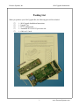
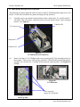
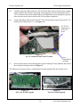
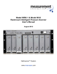
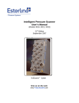
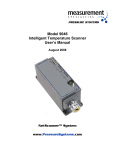
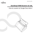
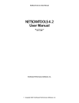
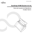
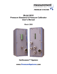
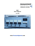
Model 9016
Upgrade Instructions
February 2004
NetScanner™ System
www.PressureSystems.com
Pressure Systems, Inc.
9016 Upgrade Instructions
Packing List
When you purchase your 9016 Upgrade Kit, the following parts will be included:
G
G
G
G
G
1 - 9016 Upgrade Installation Instructions
1 - Upgrade Tag
1 - PC327 analog board
1 - Assembled PC322-PC323 processor unit
1 - Cable tie 5.5 inch
1
www.PressureSystems.com
Pressure Systems, Inc.
9016 Upgrade Instructions
9016 Upgrade Instructions
The following instructions must be followed to successfully upgrade the hardware and firmware in
your current 9016 Intelligent Pressure Scanner to 9116 scanner capabilities.
Figure 1 is an exploded view of the Model 9016. Please refer to this drawings for an understanding
of the construction of Intelligent Pressure Scanners. Figure 2 depicts the 9016 top plate.
Figure 1
Exploded View of 9016 Scanner
Figure 2
9016 Top Plate
2
www.PressureSystems.com
Pressure Systems, Inc.
9016 Upgrade Instructions
When performing any type of maintenance of NetScanner™ System components, the
following guidelines and precautions should always be followed:
!
Verify that the work area and technicians are properly grounded to prevent
damage to electronic components due to electrostatic discharge.
!
Ensure that all electrical and pneumatic connections have been removed from the
module.
!
Ensure that the work area is free of dust and other possible contaminants that
may affect the high tolerance machined parts (and pneumatic seals, if model has
an integral manifold).
!
Care must be taken to prevent contaminants from reaching O-ring surfaces. If Oring surfaces require cleaning, use a lint-free applicator with acetone to remove
dirt and lightly lubricate the O-ring surface with Krytox® provided in the
maintenance kit.
!
Never use sharp objects to cut tubing from the bulged tubes. The tiny scratches
left on the tubes could cause leaks.
In the process of performing this upgrade, the following tools will be required:
!
!
Phillips-head screwdriver (No.1 preferred), and
small cutters.
Module Disassembly
The following procedure should be used to disassemble your model 9016 prior to this upgrade.
(1)
Place the scanner with its external connectors facing up. With one hand holding the module
housing, remove all screws securing the top plate to the module housing. These are located
around the perimeter of the top panel of the module housing. The 9016 uses twelve (12)
Phillips-head screws around the top plate outside perimeter. See Figure 3, next page.
Use caution not to slip and scratch the top plate
3
www.PressureSystems.com
Pressure Systems, Inc.
9016 Upgrade Instructions
Remove 12
perimeter Phillipshead screws.
REMOVE ONLY
THE 12
PERIMETER
SCREWS.
Figure 3
9016 Top Plate
(2)
When all screws have been removed, gently lift the top panel and attached electronics up and
out of the housing. All components of the pressure scanner are attached to the top plate and
will lift out of the module housing when the top plate is removed. See Figure 4, next page.
In some cases, it may be easier to hold the top plate and turn the module over, lifting the
housing off the top panel. If the Viton® gasket is loose, tack it down with 495 LocTite™
super bonder™. (Loctite Corp., USA) (or other suitable adhesive capable of adhering to the
gasket material and to the aluminum case).
4
www.PressureSystems.com
Pressure Systems, Inc.
9016 Upgrade Instructions
Viton® gasket
Figure 4
9016 Out of Housing
Electronic Circuit Board Replacement
Your 9016 contains two (2) electronic circuit boards that must be removed and replaced for this
upgrade.
PC-206 Amplifier/Multiplexer Board
The following procedures should be used for removal of the PC-206 Amplifier/Multiplexer Board.
Use the tools and follow the general precautions previously described.
(1)
Carefully remove the wiring harness from connector P1 of the PC-206 board. (See
Figure 5.)
(2)
Remove the two (2) Phillips-head screws securing the PC-206 board to the DH200
transducers. Carefully disconnect the PC-206 board from the DH200s by slowly working
the board off; starting at one end and moving down the length of the board. It is important
to not break the gold pins when removing the board. Inspect the PC-206 boards for broken
pins and remove from DH200 transducers, if neccessary.
Wiring harness
Phillips head screws
Figure 5
PC-206 Board
5
www.PressureSystems.com
Pressure Systems, Inc.
9016 Upgrade Instructions
PC-280 Ethernet Microprocessor/A-D Board
The following procedures should be used for removal of the PC-280 Ethernet Microprocessor/A-D
Board. Use the tools and follow the general warnings already described.
(1)
Carefully remove any attached wiring harnesses from connectors P1, P3, and P6 of the PC280 board. This will require cutting one nylon tie-wrap attached to the center mounting
bracket. (See Figure 6)
Connector P6
Tie-wrap to cut
Connector P3
Connector P1
Figure 6
PC-280 Board and Connectors
(2)
Remove the three (3) 2-56 Phillips head screws securing the PC-280 mounting brackets to
the top plate. These screws will be in line with the PC-280 LEDs that protrude through the
top plate. Save for later use. Carefully lift the board out of the top panel. (See Figures 6a
and 6b.)
Figure 6b
PC-280 Board
Three screws to
remove PC-280 board
Figure 6a
9016 Top Plate
6
www.PressureSystems.com
Pressure Systems, Inc.
9016 Upgrade Instructions
Retain all of the existing connecting cables for use with your new PC boards. The two (2) boards
you have just removed will be replaced with three (3) new printed circuit boards. The PC-206 board
will be replaced by the PC-327 Analog Board. The PC-280 board will be replaced by the PC-322
Mother Board and the PC-323 Microprocessor Board. The PC-322 and the PC-323 will arrive
attached to one another and they will be installed as a single unit.
Installing the PC-327 Analog Board
(1)
Remove the new PC-327 board from its shipping container, paying particular attention to
prevention of electrostatic discharge damage.
(2)
Place the new board on top of the DH-200s with the connector pins on the same end as the
wiring harness. Route the one tube beneath the board. (See Figure 7.) Line up the gold pins,
and gently and slowly press to connect. Pay particular attention to the C1 and C4 tubes and
ensure they are not crimped or crushed between the PCB and the DH200s. (See Figures 7
and 7a.)
WARNING: Ensure that the board is oriented the same as the board just
removed (connector pins on the same end as the wiring harness)
and the gold pins are lined up with and fit easily into the
connectors on the DH200s.
Figure 7
Tubing Routing Underneath PC-327 Board
(3)
Reinstall the two (2) Phillips-head screws to secure the PC-327 board.
7
www.PressureSystems.com
Pressure Systems, Inc.
9016 Upgrade Instructions
C1 tube
C4 tube
C4 tube
Figure 7a
PC-327 Board
Installing the PC-322/323 Boards
As previously mentioned, the PC-322 and the PC-323 boards will arrive to you completely
connected and may be installed very similarly to the installation of the old PC-280 board. (See
Figure 8.)
P1 connection
P3
connection
Figure 8
PC-322/323 Boards
P6 connection
(1)
Use the same precautions as previously noted when removing these boards from their
protective shipping container; i.e., prevention of electrostatic discharge damage.
(2)
The calibration valve control wires are attached to connector P6 (as shown in Figure 8).
The routing of these wires will need to be changed during the upgrade. The wires connected
to the four pin P6 connector will need to be freed from about one-half of the white spiral
wire wrap. This may be accomplished by unwinding approximately half of the nylon spiral
8
www.PressureSystems.com
Pressure Systems, Inc.
9016 Upgrade Instructions
wire wrap, starting near the P6 connector. The freed white nylon spiral wire wrap may be
re-used on other wires or tubes, or may simply be cut off and discarded. If you choose to cut
off the spiral wire wrap, be careful not to nick or cut any other wires or tubes.
(3)
Attach the wiring harnesses to their respective connectors, P1, P3, and P6. Note that the
connector from P3 connects to your new PC-327 board. It will be connected to the PC-327
board after the PC-322/323 boards have been attached to the module top plate. Remember,
the red line on your ribbon cable is to be connected to Pin 1 of the PCB.
(4)
Plug the connector from the top plate into P1 of the PC-322 board. Be careful to connect the
correct pins together (Pin1 to Pin1) and make sure the pins are aligned. If not, the PCB
could be damaged. Pin 1 is denoted by the square pad on the solder side of the board. (See
Figures 9, 9a, and 10.)
Pin 1, denoted
by square
solder pad (on
bottom of PC
board)
Figure 9
Finding Pin 1 on a PC
Figure 9a
Board
Orient red stripe as shown Connectors on 322/323 PCB
Scanner top plate
connection
P1 connection on
PC-322 board
Figure 10
Top Plate to P1 Connection on PC-322
9
www.PressureSystems.com
Pressure Systems, Inc.
9016 Upgrade Instructions
(5)
Carefully guide the LEDs (on the PC-322 board) into their respective holes in the scanner
chassis. Ensure that all cables and tubing are not crimped or restricted and attach the PC322/323 boards to the chassis with the three (3) Phillips-head screws through the top plate
(that were previously removed and saved). Do not tighten completely.
(6)
Connect the ribbon cable from P3 on the PC-322/323 board to the connector on your PC-327
board (red line indicates pin 1). (See Figure 11.)
PC-322/323
connection to
the PC-327
board
Figure 11
PC-327 Connection and Cable Tie-down
(7)
Note
orientation of
red stripe
Insert a plastic cable tie-down through the tie-down mount previously installed and around
the clear plastic tubing as shown in Figure 11.
The following two pictures show a completed 9016 module upgrade with side and top views.
Figure 12
Side View of 9016 Upgrade
Figure 13
Top View of 9016 Upgrade
10
www.PressureSystems.com
Pressure Systems, Inc.
9016 Upgrade Instructions
Final Installation
(1)
Carefully reinstall the module into the housing, aligning the retaining pins in the housing
with holes in the brackets on your PC-322/323 boards. Ensure that none of the wiring
harnesses or nylon tubing are pinched. Ensure the Viton® gasket is flat between the two
surfaces and is without folds. Tighten the three screws for this PC-323 board.
(2)
Re-install the twelve (12) Phillips-head screws around the top plate perimeter.
(3)
Install the upgrade kit tag on the end of your scanner, just below the serial
number/nameplate. The tag is designed to fit directly beneath the nameplate. Clean the
surface of the with isopropyl alcohol to achieve good adhesion. Peel off the protective
covering layer of double-faced tape and position the sticker as described above.
Final Checkout
Test your Intelligent Pressure Scanner for proper operation. For operation of your newly
upgraded Intelligent Pressure scanner, please refer to your 9116 User’s Manual, available
from the Pressure Systems web site, www.PressureSystems.com.
11
www.PressureSystems.com
Headquarters/Factory:
Pressure Systems, Inc.
34 Research Drive
Hampton, VA 23666
USA
Phone:
(757) 865-1243
Toll Free: (800) 328-3665
Fax:
(757) 865-8744
E-mail: [email protected]