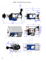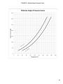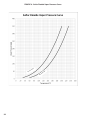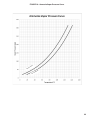
1
Series VPH-10000-2
Vaporizer
Instruction and Operation Manual
VPH-10000-2 Rev. 5/7/15
1
Hydro Instruments VPH-10000-2 Vaporizer
Table of Contents
I.Introduction............................................................................................................. 3
1. Safety Information
2. System Size, Capabilities, and Specifications
3. Units of Measurement
II.Installation............................................................................................................... 5
1. Installation of the Vaporizer
2. Installation of Chlorine Pressure Piping
3. Installation of Auxiliary Components
1. Electronic Pressure Reducing Valve
2. Pressure Relief Valve Assembly
3. Expansion Chamber Assembly
4. Electrical Installation
1. Connecting the Main Power
2. Wiring Relays and Alarm Outputs
3. Modbus Information
III.Operation............................................................................................................... 14
1. Leak Testing
2. Initial Start-Up
3. System Start
4. System Shut Down
1. Short Term Shut Down
2. Long Term Shut Down
5. Navigating the Controller
1. Explanation of Main Controller Screens
6. Operating Controls and Components
1. Chlorine Gas Temperature Thermocouple
2. Chlorine Gas Pressure Transmitter
3. Water Tank Temperature
4. Water Level Control
5. Water Re-Fill Solenoid
6. Cathodic Protection System
7. Water Heater
7. Alarms and Features
IV.Maintenance.......................................................................................................... 23
1. Yearly Maintenance
1. Chlorine Pressure Chamber Cleaning
2. Alarms and Switches Testing
3. Component Preventative Maintenance
2. 5-Year Chlorine Pressure Chamber Cleaning and Inspection
V.Troubleshooting.................................................................................................... 26
VI. Important Figures, Parts and Dimensional Drawings
1. Wiring Diagrams....................................................................................... 10-12
2. Assembly Diagrams.................................................................................. 28-30
3. Vapor Pressure Curves............................................................................... 31-33
2
I.Introduction
The contents of this manual are intended to provide information regarding the installation, operation,
maintenance and troubleshooting of Hydro Instruments’ VPH-10000-2 vaporizer. It is critically important
to read and become familiar with the contents of this entire manual before proceeding to install or operate
the unit. If you have any questions please consult Hydro Instruments.
In certain instances throughout this manual, reference may be made specifically to chlorine. However,
the information may also apply to sulfur dioxide and ammonia systems. Please consult with Hydro
Instruments if using this product for a chemical other than chlorine.
For more information on chlorine safety and handling practices, please refer to the following documents
from the Chlorine Institute:
The Chlorine Manual, Sixth ed. Washington: The Chlorine Institute, Inc., 2000.
Pamphlet 1: Chlorine Basics, Seventh ed. Washington: The Chlorine Institute, Inc., 2008.
Pamphlet 6: Piping Systems for Dry Chlorine. Fifteenth ed. Washington: The Chlorine Institute, Inc.,
2005.
Pamphlet 155: Water and Wastewater Operators Chlorine Handbook, Second ed. Washington:
The Chlorine Institute, Inc., 2008.
1.Safety Information
Warning
• Chlorine is a hazardous chemical that can cause injury and death if not handled properly. It is
critically important to take all necessary precautions when handling. This manual is not intended
to replace or limit safety procedures in your facility.
• Safety procedures must be designed in accordance with all governmental regulations and national
safety codes, after giving full consideration to the specific needs of the facility involved. Under no
circumstances should the information in this manual be construed as substituting or superseding
any local, state, or federal laws and regulations.
• Hydro Instruments cannot anticipate the specific safety procedures required at every facility. Accordingly, Hydro Instruments does not guarantee that safety procedures designed in accordance
with this manual will completely eliminate hazards and thus assumes no liability for accidents that
may occur in your facility.
• Read this entire manual and be fully familiar with your equipment and your entire system so that
the safety procedures you establish will meet the needs of the employees in you facility. Reading
only part of the manual will not help you analyze the needs of your facility. Contact your chlorine
supplier, the chlorine institute, and other similar organizations to obtain MSDS sheets and more
information.
• All information in this manual was current at time of printing. Please note the date of printing
and possible obsolescence of material as a result of scientific and medical developments after the
date of publication. This applies to all materials you review in the course of developing safety
procedures for use at your facility.
3
When working with Chlorine
• Ensure that approved, self-contained breathing and safety equipment are always available and
ready for use and personnel are properly trained for its use.
• Safety equipment should be inspected and maintained in accordance with the manufacturer’s
instructions.
• Ensure that all warning signs and placards are in their appropriate place and can clearly be
displayed.
• In the event of a leak, use proper safety equipment and trained personnel to respond to the leak
immediately. Evacuate all personnel from dangerous areas to a safe space. If breathing has
stopped perform respiration immediately. If heart has stopped perform CPR.
• Knowledgeable design personnel should oversee and approve equipment installation and suitability
of the system for which it is intended. Qualified personnel should also perform routine equipment
checks and maintenance in accordance with manufacturer’s recommendations and instructions.
2.System Size, Capabilities and Specifications
Overall height:
64" (163 cm)
Clearance space required:
24" (61 cm) on all sides. 12' (3.7 m) floor to ceiling.
Chlorine pressure chamber dry weight:
roughly 360 lb (163 kg)
Water tank dry weight:
roughly 430 lb (195 kg)
Total assembled dry weight:
roughly 790 lb (358 kg)
Rated working pressure:
560 psi (38.6 bar) - hydrostatically tested to 825 psi
(56.9 bar)
Supply pressure:
38 – 210 psi (2.6 – 14.5 bar) Cl2 and SO2
48 – 210 psi (3.3 – 14.5 bar) NH3
Maximum capacity:
10,000 PPD (200 kg/hr) Cl2
8,000 PPD (150 kg/hr) SO2
2,500 PPD (50 kg/hr) NH3
18 kW
Maximum heater output:
Power consumption:
Single phase power: 120 VAC or 240 VAC
Three phase power: between 240 VAC (44 A max)
and 480 VAC (22 A max)
Ambient temperature:
50-122ºF (10-50ºC)
Recommended torque for
pressure chamber flange bolts:
275 lb-ft (3802 N-m)
3.Units of Measurement
4
For convenience, common measurement values (temperature, pressure, length, mass, torque) will be
given in both English and equivalent Metric units. Throughout this manual, pressure values will be
shown in units of psi (bar) and denote gauge pressure (zero-referenced against atmospheric pressure.)
II.INSTALLATION
1.Installation of the Vaporizer
The VPH-10000-2 is supplied completely assembled. The user should install the vaporizer in a
location that has at least 12 ft. (3.65 m) of space from floor to ceiling. A lifting crane should also be
available at the location and should have a minimum lifting capacity of 2 tons. Additional overhead
space should be factored in for the lifting crane. The lifting crane can be used to connect to the two
1" eyebolts located on the top flange to remove the pressure chamber or move the entire vaporizer
assembly. To access the eyebolts the user must remove the fiberglass cabinet. Once in position, the
vaporizer should be bolted to the floor by the use of four, 5⁄8" concrete anchor bolts through the bottom
plate. If installing multiple vaporizers, Hydro Instruments recommends leaving at least 2 feet of
clearance space between each vaporizer for ease of access.
If using automatic water control, a ½" water pipeline should be installed to the water solenoid valve.
The water should have a minimum supply pressure of 15 psi (1 bar) and not exceed 60 psi (4 bar).
Drain ports from the vaporizer consist of a 1.5" drain valve, a 1¼" water overflow pipe and a 1 ¼" vent
pipe. For convenience all drain pipes are located on the rear side of the unit and must be plumbed on
site.
Inlet and outlet connections to the vaporizer are made through 1" NPT ammonia type unions. The
inlet connection is made through the center of the top flange. Improper installation of the inlet and
outlet piping can lead to serious malfunction of the unit and possible personal injury. The liquid
chlorine inlet port is on the center of the top flange and the chlorine gas outlet port is off center. For
added convenience, the ports are also stamped “IN” for the liquid inlet and “OUT” for the gas outlet.
2.Installation of Chlorine Pressure Piping
Connections to the vaporizer are made through the use of 1" ammonia type unions. Chlorine pressure
piping should be made of seamless schedule 80 carbon steel, and fittings must be 3000 lb forged type.
For more information on chlorine pressure piping and vaporizer piping design tips please see Chlorine
Institute’s pamphlet 6 and Hydro Instruments’ Vaporizer Piping Guide EVP-002-CL2.
3.Installation of Auxiliary Components
3.1 Electronic Pressure Reducing Valve
The electronic pressure reducing valve is an integral part of any vaporizer system. The electronic
pressure reducing valve is the device that will stop chemical feed in the event of an alarm condition.
This will prevent liquid chemical from contacting and damaging downstream equipment.
Hydro Instruments’ vaporizer allows the user to install two electronic pressure reducing valves into
the main controller. One is for operation, and the other for standy-by which can be switched to using
the main controller (see Section III.5). The electronic pressure reducing valve must be installed
downstream of the vaporizer, after the pressure relief valve assembly and filter but before the vacuum
regulator. Available in either 120 VAC or 240 VAC single phase power, the hot wire (black) should be
wired into N.O. 1 (CB-8RELAY) and the neutral wire (white) should be wired into the neutral bar in
the relay connections box, with the green wire going to ground. If using a second electronic pressure
reducing valve use N.O. 5 (CB-8RELAY). Ensure that power is disconnected from the vaporizer
before installation. Further information is available through Hydro Instruments’ electronic pressure
reducing valve instruction manual.
5
3.2 Pressure Relief Valve Assembly
The pressure relief valve assembly is a critical component to any chlorine vaporizer system and
is required by ASME code for operation. This mechanical safety device limits the pressure of the
chlorine pressure chamber to a maximum value. The rupture disc must be properly installed into the
rupture disk holder prior to installing the rupture disk assembly onto the pipe. Installation to the gas
pipeline is made through the use of 1" Ammonia type unions. The pressure relief valve assembly
should also be installed as close as possible to the vaporizer gas outlet of the pressure chamber. No
other interferences can be installed between the outlet of the vaporizer and the rupture disc of this
assembly. This assembly must be installed horizontally and in the upright position. Piping coming out
of the relief valve must be 1.5" schedule 80 seamless carbon steel and slope downward outside or to
another safe location with an insect screen on the outside end.
The pressure relief valve assembly also includes a pressure switch that may be wired into the signal
output connections box of the vaporizer for Modbus indication of rupture disc failure. It will be wired
into the V- and DI4 input terminals.
3.3 Expansion Chamber Assembly
The expansion chamber assembly is a mechanical safety device used on liquid chemical lines to
prevent pipe rupture in the event of an over pressure condition. Thus, an expansion chamber assembly
must be installed everywhere that the liquid has the potential to become trapped in the pipe. This
includes sections of pipe that could become isolated through ball valves. In any section of pipe that
an expansion chamber is installed on, it must be located at the highest point of this pipe section. The
volume of the expansion chamber must also be sized so that its volume is not less than 20% of the pipe
volume it is protecting. Supports should also be provided to the expansion chamber assembly.
The expansion chamber assembly comes with a pressure switch that may be wired into the signal
output connections box of the vaporizer for Modbus indication of rupture disc failure. It will be wired
into the V- and DI3 input terminals.
6
4.Electrical Installation
4.1 Connecting the Main Power:
The VPH-10000-2 requires three phase power. All power connections are made through the heater
control box.
Warning: Electrical shock hazard. Ensure all power is disconnected from the source before
proceeding. Ensure that only qualified personnel are working on this equipment.
a. Turn the single phase power switch off.
b. Turn the three phase disconnect switch to the off position. This will allow access to the heater
control box.
c. Unscrew the four screws on the front of the heater control box.
d. Feed the three phase cable and conduit through the 1" conduit fitting on the left side of the heater
control box. Ensure fitting is air tight.
e. Connect the three phase power into the appropriate terminals (Figure 1a-b). Be sure to tie the
ground wire to the ground block. The three phase power is for the heater, which is a delta wiring
arrangement and thus no neutral wire is needed.
f. Close the heater control box and insert screws.
g. Connect power to main source.
h. Ensure that the manual contactor override switch is in the enable position.
i. Turn the single phase and three phase disconnect switches on.
4.2 Wiring Relays and Alarm Outputs
Warning: Electrical shock hazard. Ensure all power is disconnected from the source before
proceeding. Ensure that only qualified personnel are working on this equipment.
The VPH-10000-2 comes with two pre-wired junction boxes for wiring relays, contacts and 4-20 mA
outputs without having to access the main controller. The junction box labeled “Relay Connections”
contains the terminals for wiring all the relays and alarm contact outputs. The junction box
labeled “Signal Connections” contains the terminals for wiring the 4-20 mA outputs and Modbus
communication. The terminal designations can be seen in Table 1 and Table 2.
7
Table 1: Relay Designations for Vaporizer Alarms and Relays
Vaporizer Alarm/Relay
Board Number
Relay Number
Recommended Wiring
Electronic Pressure
Reducing Valve 1
CB-8RELAY
1
N.O.
*Refill Solenoid
CB-8RELAY
2
N.O.
Not used
CB-8RELAY
3
-
*Magnetic Contactor
CB-8RELAY
4
N.O.
Electronic Pressure
Reducing Valve 2
CB-8RELAY
5
N.O.
Superheat Alarm
CB-8RELAY
6
N/A
High Pressure Alarm
CB-8RELAY
7
N/A
Water Level Alarm
CB-8RELAY
8
N/A
Low Water Temperature Alarm
CB-2RELAY
1
N/A
High Water Temperature Alarm
CB-2RELAY
2
N/A
* Wired from the factory.
Table 2: 4-20 Output Designations
Parameter
Terminal
Range
Gas Pressure
AO1
0 - 300 psi (21 bar)**
Gas Temperature
AO2
0 - 121°C (32 - 250°F)
Superheat Temperature
AO3
0 - 121°C (32 - 250°F)
Control Water Temperature
AO4
0 - 121°C (32 - 250°F)
NOT USED IN MODEL VPH-10000-2
AO5
-
Expansion Chamber Switch
DI3
closed = alarm
Pressure Relief Valve Switch
DI4
closed = alarm
Note: All outputs must also be wired to the appropriate V- (GND) terminal.
**Pressure range can be adjusted but must match the pressure transducer's specifications.
8
4.3 Modbus Information
The VPH-10000-2 can communicate with a SCADA system using Modbus RS-485 communication.
The baud rate, node number and data format of the VPH-10000-2 must match that of the master
SCADA system. See Section III.5 for information on how to access and edit these features. A table
of Modbus integers and their corresponding parameters can be seen in Table 3. For more information
on configuring Hydro Instruments equipment onto SCADA systems, please refer to the Modbus
Installation and Instruction manual.
TABLE 3: Modbus Information
Name
Type
Address
Gas Temperature
Gas Pressure
Gas Pressure Span
High Pressure Alarm Level
Superheat Temperature
Superheat Alarm Set Point
Control Water Temperature
Water Temperature Set Point
High Temperature Alarm Set Point
Low Temperature Alarm Set Point
NOT USED IN MODEL VPH-10000-2
Integer
Integer
Integer
Integer
Integer
Integer
Integer
Integer
Integer
Integer
Integer
1
2
3
4
5
6
7
8
9
10
11
Water Level
Integer
12
Heater Power Output (kW)
Heater Power Output (%)
Heater Element Temperature
Integer
Integer
Integer
13
14
15
Temperature Units
Integer
16
Pressure Units
Integer
17
Alarm Status
Integer
18
Register
Value
Feature
0
1
2
3
Normal
High
Low
Low Low
0
1
0
1
0
2
3
4
5
6
7
8
9
10
Celsius
Fahrenheit
PSI
Bar
Normal
Low Water Temperature
High Water Temperature
Heater Over Temperature
Superheat Alarm
High Water Alarm
Low Water Alarm
PRV Burst Disc
EXP Burst Disc
High Pressure
9
Figure 1: Heater Control Box Diagram for Power
3PH
Power In
10
MB181
NOT USED
PRESSURE RELIEF VALVE PRESSURE SWITCH
EXPANSION CHAMBER PRESSURE SWITCH
Figure 2: Main Controller Wiring
MB122
MB140
MB114
11
Line 1 (Black)
Ground (Green)
Figure 3: Relay Output Box
Connect
PRV #1 Here
MB108
Line 2 (Red)
Solenoid
Line 2
Line 2 (Red)
PRV #1
Line 2 (Red)
Solenoid
Not Used
Contactor
Line 2 (Red)
Heater Contactor
Optional PRV #2
Superheat Alarm
High Pressure Alarm
Water Level Alarm
MB123
Low Water Temp Alarm
High Water Temp Alarm
12
Figure 4: Vaporizer Controller
FIGURE 4: Vaporizer Controller
MAIN CONTROLLER
CATHODIC PROTECTION
CONTROL & AMMETER
HEATER
CONTROL BOX
WATER LEVEL
INDICATOR
THREE PHASE
DISCONNECT SWITCH
SINGLE PHASE
DISCONNECT SWITCH
MANUAL CONTACTOR
OVERRIDE
CONTACTOR INDICATOR
STATUS (ON = ENERGIZED)
13
III. Operation
1. Leak Testing
Please refer to and follow the leak testing procedure outlined in this section before performing the
initial start-up, if the piping has been changed, if the vaporizer has just been cleaned, or for other
situations in which air/moisture has been allowed to enter the system.
Warning: When performing this step, ensure that all protective equipment is available.
Warning: Before beginning the leak test ensure that all appropriate measures have been taken
to remove any cutting oils and/or unwanted residue from the piping system. These residues can
cause accelerated pipe corrosion and result in a leak.
NOTE: Before performing this step, be sure to read Hydro Instruments “Nitrogen Purging” document
for further information.
a. Individually leak test all expansion chamber assemblies and pressure relief assemblies before
beginning this test procedure. Also, test the operation of the pressure switch in each expansion
chamber assembly and pressure relief assembly before beginning this procedure.
b. Ensure that piping is installed correctly and securely. Also check to ensure that all the chlorine
container valves are closed and that no chlorine is in the manifold piping.
c. Connect a dry air or nitrogen supply to the end of the chlorine manifold through a ball valve
suitable for chlorine manifold service. Make sure that required pressure controls are installed to
ensure that the nitrogen or dry air pressure entering the manifold cannot exceed 150 psi (10 bar).
d. Purge the system piping with a supply of dry air or nitrogen to remove any moisture or debris (for
more information, refer to the Chlorine Institute’s pamphlet 6).
e. Once the system has been adequately purged, pressurize the piping to 150 psi (10 bar) using dry
air or nitrogen. Then close the air or nitrogen supply valve and record the pressure reading. Watch
to ensure that the pressure reading does not drop. Any drop in pressure indicates the presence of a
leak that must be identified and corrected before proceeding further.
f. Check the entire manifold for leaks using soapy water all the way up to the regulator. If bubbles
form there is a leak. The piping must be re-worked and steps d and e must be repeated.
g. Lower the nitrogen/dry air pressure to slightly below the chlorine gas pressure, and seal off the
nitrogen/dry air connection to the chlorine manifold with a valve or connection that is rated for
chlorine manifold service. Then connect the manifold to the chlorine container gas valves (do not
connect to the chlorine container liquid valves). Ensure that no moisture has been allowed to enter
the system. Close all the valves in the pipeline.
h. Open one chlorine gas container valve and its isolation valve and then quickly close them. Check
for leaks on the manifold one section at a time using a 26 Baume solution of ammonia. If white
smoke appears, there is a leak. If there is a leak, evacuate the system using the ejector and correct
the leak. Then repeat steps d through h. Correct all leaks before moving to the next step.
i. Open all manifold valves (but, keep the isolation valves and the chlorine container valves closed).
Evacuate the system using the ejector. Open one chlorine container gas valve briefly and then
close the valves quickly to reintroduce chlorine gas into the system. Then check for leaks one
section at a time all the way up to the regulator using a 26 Baume solution of ammonia.
j. With the chlorine gas container valves and isolation valves still closed, evacuate the system by
operating the ejector until the pressure reads (and holds at) 0 psi (0 bar).
14
2.Initial Start-Up
Only refer to the start-up procedure outlined in this section if the previous Section III.1 leak test has
already been completed and you are now performing the initial start-up, the piping has been changed,
the vaporizer has just been cleaned, or in any other situation in which air/moisture has been allowed to
enter the system.
Warning: When performing this step, ensure that all protective equipment for handling chlorine
gas is available.
a. Ensure that piping is installed correctly and securely and the leak test from Section III.1 has
already been completed successfully.
b. Check to ensure that all the chlorine container valves are closed and that no chlorine is in the
piping.
c. Turn the vaporizer on (both single phase and three phase power). Immediately the low water alarm
will turn on and open the water solenoid valve to allow water into the water tank. At this point
also check to see that the low water temperature alarm, and the low superheat alarm are all on (if
applicable).
d. Once the water has reached operating level, check to see that the alarm condition has cleared and
the solenoid valve is completely closed (ensure that no water is coming out of the drain port).
e. Check to see that the heater is working by monitoring the water temperature. The factory set
operating water temperature of the vaporizer is 180˚F (82˚C). The vaporizer should take 3060 minutes to heat up, depending on incoming water temperature. Check that the low water
temperature alarm has turned off once the water temperature has risen to the appropriate set point
value.
f. Adjust the cathodic protection, using the potentiometer above the ammeter. Operating current
should be between 50-250 mA. Add ¼ lb (113 g) of sodium sulphate to increase the conductivity
if the requirement cannot be met.
Note: Due to the enamel painting of the chlorine pressure chamber, a low/no current reading
may appear during the first 6 months of operation. This is normal and the vaporizer is still being
protected.
g. Connect the manifold to the chlorine container gas valves via flexible connectors/isolation valves.
Open the isolation valves connected to each container. Open one chlorine container gas valve
and quickly close it again. Check for leaks one section at a time using a 26 Baume solution of
ammonia. If white smoke appears, there is a leak. If there is a leak, evacuate the system using
the ejector and correct the leak. Then retest the piping to ensure that there are no leaks before
proceeding to the next step.
h. With the chlorine gas valves closed, evacuate the system by operating the ejector until the pressure
transmitter on the vaporizer reads (and holds at) 0 psi (0 bar). Close the isolation valves and
connect them to the liquid chlorine header valves. Also close any valves that are in the liquid
manifold pipeline. If using multiple ton containers and a gas pressure equalization manifold, then
make the connections to this gas pressure equalization manifold and open those valves before
opening the liquid chlorine container valves. Open the liquid chlorine header valves, and slowly
introduce the liquid chlorine into the system by opening one chlorine container liquid valve at a
time. Once all the liquid container valves are open, gradually introduce liquid chlorine into the
rest of the manifold by opening the remaining valves one section at a time. Operate the vaporizer
at 25% of scale until equilibrium is reached (when temperature and pressure readings are constant
over a set period of time).
15
Warning: Ensure that the water tank temperature is 180˚F (82˚C). Liquid chlorine should
never be allowed into the vaporizer without the water tank temperature being in the
operating range.
i. Bring the vaporizer up to 50% and allow the system to reach equilibrium. Do the same at 75% of
scale and 100 % of scale.
3.System Start
This procedure may only be used after the initial start-up has been completed or if restarting the
system and the user is sure that no moisture has been allowed into the system and that no leaks are
present. If unsure, use the start-up procedure outlined in Section III.2.
Warning: When performing this step, ensure that all protective equipment for handling chlorine
gas is available.
a. Ensure that the chlorine container valves are closed and there is no chlorine in the piping. Turn on
the vaporizer, check to make sure that the water has filled up and the water tank temperature is at
operating level. Check that all appropriate alarms have turned off.
b. Connect piping to the chlorine gas container valves and allow chlorine gas into the system. Close
the gas container valves and check for leaks using a 26 Baume solution of ammonia. If white
smoke appears, a leak is present and corrective action must be taken.
c. Run the ejector(s) to remove chlorine from the pipeline. Close the isolation valves and connect the
manifold to the liquid chlorine container valves.
d. Close all valves in the manifold pipeline. Open the isolation valves, and slowly open the liquid
chlorine container valves and introduce liquid chlorine into the manifold piping.
e. Open the remaining valves one by one until they are all open.
f. Operate the vaporizer at 25% of full scale until equilibrium has been reached. Then bring up
to 50%, 75% and full scale making sure equilibrium has been established each time (when
temperature and pressure readings are constant over a set period of time).
Warning: Do not introduce liquid chlorine into the vaporizer without the water tank
temperature at operating conditions.
4.System Shut Down
4.1Short Term Shut Down
A short term shut down is defined as any situation where the chemical feed is only temporarily
interrupted, and the heater and all control functions will remain on. Hydro Instruments recommends
the following procedure:
a. If applicable, temporarily stop chemical feed at the vacuum regulator and allow liquid to fill back
into the container.
b. Once equilibrium has been reached (when temperature and pressure readings are constant over a
set period of time), shut the liquid & gas chlorine container valves. Keep all manifold valves open. c. Run the ejector to remove all the chlorine from the pipeline until the chlorine pressure reading
reads zero. Wait for 30 minutes to ensure pressure readings hold at 0 psi and then repeat this step
as necessary.
16
d. Close the isolation valves.
Warning: Ensure that the chlorine containers can handle the amount of chemical going back
into the container. Overfilled containers will result in a chlorine leak.
4.2Long Term Shut Down
A long term shut down is defined as any situation where the chemical feed is going to be stopped
and the heater and all control functions will also be shut down. Hydro Instruments recommends the
following procedure:
a. If applicable, temporarily stop chemical feed at the vacuum regulator and allow liquid to fill back
into the container.
b. Once equilibrium has been reached (when temperature and pressure readings are constant over a
set period of time), shut the liquid & gas chlorine container valves. Keep all manifold valves open.
c. Run the ejector to remove all the chlorine from the pipeline until the chlorine pressure gauges read
zero. Wait for 30 minutes to ensure pressure readings hold at 0 psi and then repeat this step as
necessary.
d. Purge the system with dry air or nitrogen according to the instructions in the Hydro Instruments
Nitrogen Purging document. Then operate the ejector again to remove all gas from the system
until the pressure gauges read zero.
e. Close the isolation valves.
f. Once established that all the chlorine is evacuated (pressure readings hold at zero), disconnect all
power to the vaporizer. Switch to the stand-by unit if necessary.
g. Open the drain valve to allow the water in the water tank to drain.
Warning: The water and vaporizer components/equipment will be very hot, 180˚F (82˚C),
so be careful when handling and/or give the water time to cool before draining.
Warning: Ensure that the chlorine containers can handle the amount of chemical going back
into the container. Overfilled containers will result in a chlorine leak.
5.Navigating the Controller
The vaporizer is provided with a Nema 4x, 2 line alphanumeric display controller that will display and
output all important features and conditions. Navigating the controller is done by the use of four push
button keys. The push button functions are described below.
key: Cycles to the previous screen.
key: Cycles to the next screen.
key: Increases/changes value. Also used to enter screens
key: Decreases/changes value.
Note: When adjusting parameter values, the number displayed is automatically saved upon leaving
the screen. Thus no “enter” button is needed.
Password: All editable features for the VPH-10000-2 are password protected to prevent unwanted
tampering with the values. To access these screens the correct password must be entered to proceed.
The password for the VPH-10000-2 is “100”.
17
Figure 5: Operating/Configuration Screens
Figure 5. Operating/Configuration Screens
18
1
Cl2 T=100F P= 85 psi
Superheat = 32 F
12
Select PRV on Duty
PRV#1/Relay1
2
Control Water Temp
180 F
13
Modbus Baud=250000
Node=1
Data=8/N/1
3
Heater Power
9.0 kW (50%)
14*
Cl2 Pressure Span
300 psi
4
Solenoid = Closed
Hold “+” to Open
15*
T180 S=180 O=50 E00
G=3.0 I=1.0 LT=5
5
Alarm Status
Normal
16*
Heater Sheath Temp
300 F
6
Enter Password
100
17*
Select Gas Type
Cl2
7
Temperature Units =F
Pressure Units = psi
8
Water Temp Alarm
Low= 160F High= 205F
9
Gas Pressure Alarm
250 psi
10
Super Heat Alm Temp
20F (0 = off)
11
Super Heat Alm Type
Non-latching
* These menus are referred to as hidden
screens and are not visible under normal
operation. To access these screens, go
to screen 13 and with the node number
blinking press and hold the down key
until screen 14 appears. The remaining
screens may be accessed by pressing
the down key after screen 14 appears.
5.1Explanation of Main Controller Screens
1.
Operation Screen: This screen displays a live reading of the pressure chamber operating
conditions. These parameters include: gas temperature, gas pressure and superheat.
2.
Water Temperature: This screen displays a live reading of the water tank temperature. This is
the temperature reading that is used for PID control of the water temperature and all appropriate
water temperature alarms.
3.
NOT USED in Model VPH-10000-2.
4.
Heater Power: This screen displays the instantaneous heater power/energy output. The value
displayed is based on the 4-20 mA control signal sent to the heater control box. This provides the
current energy consumption and provides some indication that chamber/heater cleaning is required
due to irregularly high consumption.
5.
Solenoid Override: This screen displays the current status of the water refill solenoid (either open
or closed). From this screen the solenoid can be overridden from normal operation to open (and
fill the water tank) by pressing and holding the
key.
6.
Alarm Status: This screen displays any alarm conditions that may currently be active, or displays
“normal” if no alarm conditions exist. If multiple alarms exist, the controller will cycle all
active alarms on this screen every two seconds. For more information on alarm conditions and
preventative actions refer to Sections III.7 and V.
7.
Password Screen: This screen allows access to all the editable features of the VPH-10000-2.
To access the configuration screens the correct password must be entered on this screen. The
password for the VPH-10000-2 is “100” and can be entered using the
and
keys. Once the
key to access the remaining screens.
correct password is blinking the user may press the
8.
Vaporizer Units: This screen allows the user to adjust the operating units used. Temperature
values can be displayed in either degrees Fahrenheit (F) or in degrees Celsius (C). Pressure values
can be displayed in either psig (psi) or barg (bar). To change units, press the
or
key until the
key.
appropriate parameter is blinking, then press the
9.
Water Temperature Alarm: This screen allows the user to adjust the high and low water
temperature alarm settings. Due to inherent safety and design features the adjustable range of the
low water temperature alarm has been set to 160 – 170˚F (71 – 77˚C) and the adjustable range of
the high water temperature alarm has been set to 195 – 205˚F (91 – 96˚C). To change values, press
the
or
key until the appropriate parameter is blinking, then press the
key to increase or the
key to decrease.
10.Gas Pressure Alarm: This screen allows the user to adjust the pressure value above which the gas
pressure alarm will activate. This setting has an adjustable range of 250 – 300 psi (17 – 21 bar). To edit this value, press the
and
keys when this value is blinking until the appropriate value
is achieved.
11.Super Heat Alarm Temperature: This screen allows the user to adjust the minimum allowable
superheat temperature, below which the alarm and all relevant functions will activate (Section
III.7). This value is adjustable from 0 – 50˚F (0 – 27˚C) with “0” disabling the alarm. To edit this
value, press the
and
keys when this value is blinking until the appropriate value is achieved.
Recommended superheat alarm values are: 20ºF for chlorine, 30ºF for sulfur dioxide, and 12ºF for
ammonia.
19
12.
Super Heat Alarm Type: The superheat alarm has the option of either being in the non-latching
mode, or completely disabled. If disable is chosen then there will be no alarm indication and the
system will not shut down based on a low superheat condition. To change the alarm type, press the
key on this screen until the correct type is blinking.
13.
Pressure Reducing Valve Duty/Standby Screen: When using two pressure reducing valves in
the system one must be designated as the duty (active) pressure reducing valve, with the other
inherently in standby. On this screen the user can select whether they want the pressure reducing
valve in relay 1 active or the pressure reducing valve on relay 5 active.
14.
Modbus: This screen enables the user to adjust the Modbus communication settings to be able to
communicate with a SCADA system. Refer to separate “MODBUS Communication Manual” for
details.
15.
Pressure Range Screen: If desired, a different scale pressure transmitter may be used to monitor
pressure. The new span must then be adjusted on this screen to match the incoming 4-20 mA
signal. Consult Hydro Instruments before changing pressure ranges or pressure transmitters.
16.
PID Control Setting: This screen displays and allows the user to adjust the PID control settings
of the vaporizer. The user can adjust the control water temperature set point (S), the gain (G), the
integral (I) and the lag time (LT). Live values are also displayed on this screen such as, control
water temperature (T), heater output (O), and the integral error (E).
17.
Heater Element Sheath Temperature: This screen displays the temperature of the heater
elements. It is used for diagnostic purposes only and to trigger disconnection of power to the
heater if the temperature rises too high.
18.
Gas Type: This screen allows the user to select the chemical feed type depending on the
application. Choices are between chlorine (Cl2), sulfur dioxide (SO2), and ammonia (NH3).
20
6. Operating Controls and Components
1.
Chlorine Gas Temperature Thermocouple: The chlorine gas outlet temperature is monitored
by a K-type thermocouple through the top flange of the chlorine pressure chamber. For added
corrosion protection it is installed with a Hastelloy-C thermowell. Its main function is to provide
visual indication of the chlorine gas outlet temperature, and together with the chlorine gas pressure
transmitter, is used to calculate and then display the superheat value. Should the amount of
superheat go below the alarm level, an alarm will be activated to shut down the pressure reducing
valve, and thereby prevent liquid chlorine from flooding through the vaporizer.
2.
Chlorine Gas Pressure Transmitter: The chlorine gas outlet pressure is monitored by a
diaphragm protected pressure transmitter. The scale of the transmitter is 0 – 300 psi (0 – 21 bar).
Its main use is to provide visual indication of the chlorine gas pressure in the chlorine pressure
chamber, and together with the chlorine gas temperature thermocouple, is used to calculate and
then display the superheat value. The operating pressure of the vaporizer should be in the range of
38 – 210 psi (2.6 – 14.5 bar). Should the pressure go outside this range corrective action must be
taken (see Troubleshooting).
3.
Water Tank Temperature Thermocouple: The water tank temperature is controlled and
monitored by one K-type thermocouple. The thermocouple is located in the water tank. The water
temperature thermocouple is used for PID control of the heater to maintain a stable water tank
temperature of 180˚F (82˚C). It provides the measurements for the low water temperature alarm
and high water temperature alarm.
4.
Water Level Control: Water level in the water tank can be controlled both automatically and/or
manually. For automatic control, there are four conductive level sensors in the water tank (one low
level, one low fill, one high fill, and one overfill alarm). Each alarm is then used in conjunction
with the water re-fill solenoid to open or close the solenoid and maintain the water level. For
manual control, there is a clear glass sight tube on the front panel for the user to determine the
operating level. When the sight glass is below 1⁄3 full, water should be added. When the water is
above 2⁄3 full water should be stopped. Water may be manually refilled using the 3" through hole
on the collar plate, or piping into the existing ½" water re-fill solenoid slot.
5.
Water Refill Solenoid: The water refill solenoid is used for automatic control of the water level.
It is 2-way, normally closed, Nema 4x rated, with stainless steel housing and is available in either
120 VAC or 240 VAC. Inlet and outlet connections are ½" FNPT. Water supply pressure must be
at least 10 psi (0.7 bar) and less than 60 psi (4.1 bar).
6.
Cathodic Protection System: Corrosion protection of the chlorine pressure chamber, water tank,
water tank piping and all other components is provided by the use of four (4) sacrificial magnesium
anodes. The amount of protection provided is adjustable by using the potentiometer next to the
ammeter. The amount of current provided should be in the range of 50-250 mA. Any more will
unnecessarily consume the anodes and any less will provide insufficient cathodic protection. A
¼ lb (113 g) of sodium sulphate should be added if this amount of current cannot be regularly
supplied. Based on normal operating conditions these anodes will be consumed in about one (1)
year, and should be replaced yearly. During initial operation little to no current may appear on
the controller due to the electrical insulation provided by the enamel painting. This is normal and
may take up to 6 months until a reading appears. The vaporizer is still being protected during this
period.
7.
Water Heater: The water heater is a 4-inch flanged type 18 kW electric heater and includes an
over temperature thermocouple to shut off the heater in case of malfunction. The heater will also
be shut off by the controller in the case of a low water level or high water temperature alarm.
Confirm that the voltage requirements of the heater match that of the incoming three phase power
supply before operation.
21
7.Alarms and Features
Refer to Table 4 for a description, and action of all alarms incorporated into the vaporizer unit. Note
that while some alarms take preventative action themselves, an operator should always monitor an
alarm situation and take preventative action if need be or the situation persists. For information on
troubleshooting techniques see Section V.
The vaporizer controller is equipped with a red LED for alarm indication. All relevant alarms will
appear on the alarm screen in two second intervals should multiple alarm conditions exist.
Table 4: Vaporizer Alarms
Alarm
Description
Action Taken by Controller
Low Superheat
The temperature of the outlet gas is less
than the alarm value.
Shut off the electronic pressure reducing
valve until desired superheat is achieved.
High Cl2 Pressure
Pressure in the chlorine pressure chamber
exceeds the alarm value.
Shut off the heater. Action must be
taken by user to reduce pressure. See
troubleshooting.
Low Water Temp
The water temperature is lower than the
alarm value.
Shut off pressure reducing valve until
desired water temperature is achieved.
High Water Temp
The water temperature is above the alarm
value.
Water heater is shut off until water
temperature is below the alarm value.
Low Water Level
Water height is below the minimum
operating level.
Shut off heater and pressure reducing
valve. Open water solenoid until desired
water level is achieved.
Water Overfill
The water level is too close to the tank’s
ceiling.
None. Action must be taken by user.
See troubleshooting.
EXP Burst Disc
The rupture disc of an expansion chamber None. Action must be taken by user.
assembly has blown. Pressure switch must See troubleshooting.
be wired into main controller for actuation.
PRV Burst Disc
The rupture disc of the pressure relief
None. Action must be taken by user.
assembly has blown. Pressure switch must See troubleshooting.
be wired into main controller for actuation.
22
IV. MAINTENANCE
1.Yearly Maintenance
1.1 Chlorine Pressure Chamber Cleaning
It is important to inspect and clean the chlorine pressure chamber for signs of corrosion, buildup of
debris and clogging. It is recommended to be done on a yearly basis. Ignoring this maintenance
step can lead to serious malfunctions of the vaporizer. In some instances it may be cheaper, less
time consuming and more reliable to replace the chlorine pressure chamber rather than clean it. The
operator should determine this on a case by case basis.
Warning: When performing this step, ensure that all protective equipment for handling chlorine
gas/liquid is available.
a. Refer to Section III.4.2 and complete the long term shutdown, ensuring that all chlorine has been
purged from the system.
b. Disconnect all power and remove all electrical connections to the top flange and collar plate.
Disconnect the inlet and outlet unions.
c. Remove the fiberglass cabinet.
d. Using a flashlight, inspect the outer surface of the chlorine pressure chamber using the 3"
inspection hole in the collar plate. If signs of corrosion exist, proceed to Section IV.2.
e. Disconnect the collar plate from the water tank and use the overhead lift to move the inner chamber
assembly to a well-ventilated location.
f. Remove the top flange of the inner chamber assembly. Using a flashlight, inspect the lead gasket
seal areas and the interior of the inner chlorine pressure chamber for corrosion and residue. If
signs of corrosion exist, proceed to Section IV.2.
g. Using water or appropriate cleaner, purge the internal surfaces of the inner chlorine pressure
chamber until all residue has been removed.
h. Once clean, inspect again for signs of corrosion. If signs of corrosion exist, proceed to Section
IV.2.
i. Using a new lead gasket, install the flange onto the chlorine pressure chamber. Be sure to replace
any worn or damaged flange nuts or bolts. Torque pressure chamber bolts to 275 lb-ft (3802 N-m).
j. Clean water tank and remove any magnesium that may have deposited on the bottom of the water
tank.
k. Install the chlorine pressure chamber onto the water bath tank with a new rubber gasket and
connect the process piping. Be sure to replace any worn or damaged flange nuts or bolts.
l. Remove and inspect the heater elements for calcium or other build up that will result in inefficient
heat transfer. Clean the elements and heater assembly before re-assembly and replace the heater
gasket.
m. Re-install all electrical connections/instruments, connect the power, and reconnect the chlorine
manifold piping with new lead gaskets.
n. Proceed to Sections III.1 and III.2 for leak testing and initial start up to resume chemical feed.
23
1.2. Alarms and Switches Testing
Alarms and switches should be tested at least once a year. Before proceeding to perform any testing or
maintenance ensure that all chlorine has been completely purged from the system and that the chlorine
container valves and inlet manifold piping valves are closed. Please refer to Section III.4.2 for long
term system shut down before performing any of the below procedures. After performing any of these
procedures, then refer to Sections III.1 and III.2 for leak testing and initial start up to resume chemical
feed.
Pressure Switch Testing for Relief Valve Assemblies and Expansion Chamber Assemblies
a. Remove the pressure switches from the pressure relief and expansion chamber assemblies.
b. Apply air pressure at approximately 50 – 100 psi (3 – 7 bar) to each pressure switch to verify
operation.
c. Replace any pressure switches that fail this testing.
d. Install tested pressure switches back into each assembly using an appropriate thread sealant.
Chlorine Gas High Pressure Alarm Testing
a. Remove the pressure transmitter assembly with diaphragm protector from the inner chlorine
chamber top flange.
b. Carefully apply nitrogen pressure, slowly increasing to about 300 psi (21 bar), to verify that the
high chlorine gas pressure alarm will activate at 250 psi (17 bar) on the vaporizer controller.
c. Replace the pressure transmitter assembly if it fails this testing (if the corresponding relay on the
controller fails then take corrective action).
d. Install tested pressure transmitter assembly with diaphragm protector back onto the top flange of
the inner chlorine chamber assembly using an appropriate thread sealant.
Pressure Relief Valve
a. Remove the Pressure Relief Valve.
b. Carefully apply nitrogen pressure, slowly increasing to about 600 psi (41 bar), to verify that the
Pressure Relief Valve will open at 560 psi (39 bar).
c. Replace the Pressure Relief Valve if it fails this testing.
d. Install tested Pressure Relief Valve back onto the assembly.
Water Level Alarm Testing
a. Turn on the vaporizer unit and allow the water to automatically fill the tank.
b. The low water level alarm should be on until the water in the sight glass reaches the low water
alarm level marking.
c. The solenoid should remain open until the water level in the sight glass reaches the high water fill
level marking. Then the solenoid should automatically close.
d. If desired, open the drain valve to bring the water level down to the low fill level to verify that the
solenoid will then automatically open to start refilling water into the tank.
e. If desired, test the water level overfill alarm by manually opening the solenoid valve until the water
level in the sight glass reaches the overfill level. At this level, the overfill alarm should activate.
24
Water Tank Temperature Alarm Testing
a. Remove the water temperature thermocouple from the water tank flange, leaving the thermocouple
extension cable (yellow) connected.
b. Place in a bath of room temperature water, allow the sensor to reach equilibrium and check the low
water temperature alarm will activate.
c. To check the high water temperature alarm, boil water in a separate container. Place the
thermocouple in the nearly boiling water (approximately 210ºF / 99ºC) to verify that the high water
temperature alarm will activate.
d. Reinstall the thermocouple onto the water tank flange.
Superheat Alarm Testing
The superheat alarm can be tested by placing the chlorine gas temperature probe in ice water during
the pressure switch alarm testing.
Cathodic Protection Testing
At the top of the water tank flange, unfasten the screw and wire connectors from the magnesium anode
nearest the ammeter. The current value should then drop to zero.
1.3 Component Preventative Maintenance
All rupture discs should be replaced on a yearly basis. O-rings and gaskets should also be replaced
yearly or sooner if they appear cracked/damaged in any way. Before proceeding to perform any testing
or maintenance ensure that there is no chlorine in the system and that the chlorine inlet piping is shut
off. Please refer to Section III.4.2 for system shut down.
Magnesium Anode Replacement
Based on normal operating conditions, the four (4) sacrificial magnesium anodes will need to be
replaced yearly or more often if necessary. This is a very important step as it protects the chlorine
pressure chamber and all other system components from corrosion.
a. Remove wires connected to the anodes.
b. Remove anodes.
c. Install new anodes into the respective locations and attach the anode wires.
2.5-Year Chlorine Pressure Chamber Cleaning and Inspection
This step should be conducted at least every five years or if signs of corrosion exist.
a. Complete Section IV.1.1 chlorine pressure chamber cleaning (perform steps a through h only).
b. Weigh the inner chlorine chamber assembly (less the process instrumentation, water tank bolts,
anodes and fittings, and inlet/outlet pipe.) and record the weight.
c. If the weight of the inner pressure chamber is 10 or more pounds lower than the original weight,
or corrosion pits exceed 1⁄8" (0.3 cm) depth anywhere on the chamber, it must be replaced. This
weight includes the top flange, flange bolts, and lead gasket. Original weight is stamped on the
pressure chamber and also stored with Hydro Instruments for future reference.
d. Complete Section IV.1 steps i through n.
25
V. TROUBLESHOOTING:
Refer to Table 5 for common problems and troubleshooting techniques for the vaporizer system. For
questions please consult Hydro Instruments.
Table 5: Troubleshooting Chart
Problem
Probable Cause(s)
Corrective Action
• Liquid chlorine in
vacuum piping
• Demand has exceeded design capacity • Lower capacity to within design flow
rate
• Damaged vacuum
piping and equipment
(vacuum regulator)
• Fouling of pressure chamber
• High pressure in
chlorine pressure
chamber
• Faulty chlorine temperature or
pressure sensor did not allow PRV to
close
• Clean inside and outside of chlorine
pressure chamber (follow appropriate
shut down and cleaning procedures)
• Supply pressure too high
• Reduce cylinder pressure
• Low water temperature/level and
failed switches
• Check and replace equipment.
• By-pass piping through PRV is open
• Check that by-pass piping is not open
• Inlet chemical pressure is too high
• Lower the room temperature or
decrease the amount of gas padding.
• Valves closed before and after
vaporizer
• Open the supply valves
• Blockage in supply line
• Evacuate and shut down system.
Clean/replace piping
• Leaking chlorine
• Rupture disc has burst due to
through pressure relief overpressure
valve (pressure switch
activated)
• Follow long term shutdown to
evacuate chemical. Replace rupture
disc
• Pressure switch
activated from
expansion chamber
assembly
• Rupture disc has burst due to
entrapment of liquid chlorine
• Follow the long term shut down
procedure and replace the broken
rupture disc
• Failed/improperly wired temperature
control circuit
• Check wiring. Replace equipment if
correct
• High pressure in
liquid pipeline
• High water
temperature
• Failed/improperly wired heater
26
Problem
• Low water
temperature
Probable Cause(s)
• Chemical capacity exceeded
• Lower feed capacity
• Improper wiring/failed heater.
Fouling of heater surface
• Check wiring/replace or clean heater
• Improper wiring/failed temperature
controller
• Check wiring/replace PID controller
• Solenoid is stuck open allowing cold
water
• Close/replace solenoid. If low water
level exists, allow for the water level
to reach set point before making any
changes
• Low water level alarm • Water level is below operating set
point
• Low water alarm
• Pump shut down and
heater is shut off
Corrective Action
• Solenoid failed closed
• Check solenoid for correct operation
• Check level probes for correct
operation
• Check for water leaks
• Overfill alarm
• Water overflowing
through drain
• Electronic PRV is
closed while trying to
chlorinate
• No cathodic
protection
• Water level is above operating set
point
• Solenoid is stuck open. Clean or
replace
• Solenoid failed open
• Replace water level control circuitry
• No power to the actuator
• Restore power to unit
• Alarm condition exists
• Check operating parameter and adjust
improper conditions
• Actuator failed
• Inspect and replace actuator
• Insufficient conductivity in water
• Anodes are consumed
• Add ¼ lb. (113 g) sodium sulphate to
water
• Circuitry improperly connected
• Replace anodes
• Check circuitry
• Low superheat
• Design capacity exceeded
• Lower feed rate
• Fouling inside/outside of pressure
chamber
• Clean chlorine pressure chamber
• Low water temperature
• Follow corrective action for low water
temperature and/or low water level
• Low water level
• Corrosion of chlorine
pressure chamber
• Poor cathodic protection
• Check anodes and cathodic protection
system
• Moisture in manifold piping
• Replace chlorine pressure chamber
if weight is more than 10 lb (4.5 g)
lighter than factory weight or if
corrosion anywhere exceeds 1⁄8"
(0.3 cm).
27
VI. IMPORTANT FIGURES
FIGURE6a:
6a: Vaporizer
Vaporizer Parts
Figure
PartsDiagram
Diagram
27
29
30
28
13
14
12
10
11
1
9
2
3
8
4
5
6
8
16
7
22
23
19
15
17
26
23
28
19
24
Figure 6b: Vaporizer Parts List
Item No.
Hydro Part Number
Description
Qty.
1
VPH-10000-PT-300
Cl2 pressure transmitter
1
1
VPH-10000-PT-300A
NH3 pressure transmitter
1
2
VPH-10000-TC-K-GAS
Gas temperature thermocouple, Type K
1
3
VPH-10000-TC-TW
Cl2 thermowell
1
3
VPH-10000-TC-TWA
NH3 thermowell
1
4
VPH-10000-3
Pressure chamber top flange
1
5
VPH-10000-FB-1
Pressure chamber flange bolts
12
6
VPH-10000-FN-1
Pressure chamber flange nuts
12
7
VPH-10000-MRA
Magnesium anode adaptor
4
8
VPH-10000-2-MAG-SET
Set of four (4) magnesium anodes
1
9
VPH-10000-000-2
Chlorine pressure chamber (complete assembly)
1
10
VPH-10000-FB2
Water tank flange bolts
8
11
VPH-10000-FN2
Water tank flange nuts
8
12
VPH-10000-002
Water bath flange gasket
1
13
VPH-10000-LE
Lifting eyebolts
2
14
VPH-10000-001
Pressure chamber flange gasket
1
15
VPH-10000-003
Level sensor mounting assembly
1
16
VPH-10000-LP
Water level sensor
1
17
VPH-10000-PP
3" View port cap
1
19
VPH-10000-2-H-240
Heater, 18kW, 240VAC, 3PH
1
19
VPH-10000-2-H-380
Heater, 18kW, 380VAC, 3PH
1
19
VPH-10000-2-H-480
Heater, 18kW, 480VAC, 3PH
1
22
VPH-10000-MB-2
Floor plate mounting bracket
1
23
VPH-10000-WS-120
Water Refill Solenoid (120 VAC)
1
23
VPH-10000-WS-240
Water Refill Solenoid (240 VAC)
1
24
VPH-10000-Corp-1.5
Stainless steel drain valve
1
26
VPH-10000-000-1
Water Tank (no piping/fittings)
1
27
VPH-10000-CSP-1
Vaporizer inlet pipe
1
28
AH-1642
Vaporizer inlet/outlet union
2
29
VPH-10000-CSP-2
Vaporizer outlet pipe
1
30
VPH-10000-2-TC-K-H2O
Water Tank Thermocouple (Type K)
1
29
30
MAIN
CONTROLLER
MANUAL CONTACTOR
OVERRIDE
HEATER
CONTROL BOX
3
33 8" 848
25" 635
16" 424
11
16
5
10 8" 269
1
47 4" 1200
CATHODIC PROTECTION
CONTROL & AMMETER
WATER LEVEL
PROBE (4 DEPTHS)
MAGNESIUM ANODE
& ADAPTOR (4 PLACES)
22" 559
VPH-10000-2 (Dimensions)
2015-04-28A
Hydro Instruments
1
2 2" 64
CONTACTOR INDICATOR
STATUS (ON = ENERGIZED)
SINGLE PHASE
DISCONNECT SWITCH
THREE PHASE
DISCONNECT SWITCH
WATER LEVEL
INDICATOR
WATER TEMPERATURE
THERMOCOUPLE
8" 203
GAS TEMPERATURE
THERMOCOUPLE
3
21 4" 552
MINIMUM DISTANCE
TO REMOVE HEATER
5
71 16" 1812
CABINET
22" 559
1
16 4" 413
5" 127
5
17 16" 440
7
22 8" 581
18 KW
HEATER
55 8" 1407
3
1 1/4" NPT
OVERFLOW
16" 68
11
2
3
3 4" 95
GAS OUTLET
1" AMMONIA TYPE UNION
1/2" NPT
SOLENOID
LIQUID INLET
1" AMMONIA TYPE UNION
5
95 16" 2422
HEADROOM REQUIRED
TO REMOVE GAS
CHAMBER
1 1/2" NPT
DRAIN
15
5
6 8" 168
5
2 8" 67
3
56 8" 1432
64
16" 1649
WATER REFILL SOLENOID
WITH UNION COUPLINGS
3
21 4" 552
MINIMUM DISTANCE
TO REMOVE HEATER
Figure 7: VPH-10000-2 Dimensional Drawing
Figure 6. Chlorine Vapor Pressure Curve
Figure 8: Chlorine Vapor Pressure Curve
re
r
po
Va
su
es
Pr
31
Figure 7. Sulfur Dioxide Vapor Pressure Curve
Figure 9: Sulfur Dioxide Vapor Pressure Curve
P
or
Vap
e
sur
res
n.
Mi
32
rhe
S
e
up
at
Figure 8. Ammonia Vapor Pressure Curve
Figure 10: Ammonia Vapor Pressure Curve
e
sur
res
P
r
po
Va
pe
. Su
at
rhe
n
Mi
33