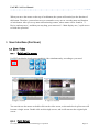
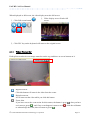
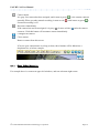
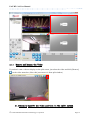
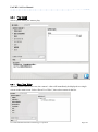
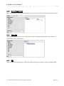
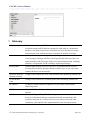
1
Global Information Technology Corp. UniVRT (UniArgus Video Recording and Transponding) V3.0 User Manual UniVRT v3.0 User Manual Contents 1 Preface .................................................................................................................... 5 1.1 Abstract...................................................................................................................... 5 1.1.1 UniVRT.................................................................................................................. 5 1.1.2 Hercules Tools-w.............................................................................................. 5 1.1.3 eLook Mobile Cam.............................................................................................. 5 1.1.4 HermesDDS Service............................................................................................ 5 1.2 System Requirements................................................................................................ 6 1.2.1 Server.................................................................................................................. 6 1.2.2 Client.................................................................................................................. 6 1.3 Admin............................................................................................................................ 6 1.4 User .............................................................................................................................. 6 2 Basic Usage ............................................................................................................ 7 2.1 Login UniVRT.............................................................................................................. 7 2.1.1 Server and Client Application Icons ....................................................... 7 2.1.2 Login.................................................................................................................... 8 2.1.3 Remote login...................................................................................................... 8 2.1.4 Logout................................................................................................................ 10 2.2 Introduction to the User Interface................................................................ 11 3 User Interface (For User) ..................................................................................... 12 3.1 Live Video................................................................................................................ 12 3.1.1 Multi-split screen........................................................................................ 12 3.1.2 Full Screen...................................................................................................... 12 3.1.3 Video Status Bar............................................................................................ 13 3.1.4 Move Video Manually...................................................................................... 14 3.1.5 Remove and Reopen the Video...................................................................... 16 3.1.6 Manually specify the video position in the split screen .............. 16 3.1.7 Manual Recording and Snapshot ................................................................. 17 3.2 Query Video and Playback.................................................................................... 19 3.3 Query and play Event............................................................................................ 26 4 3.4 3.5 Audio Setting in Playback Video...................................................................... 27 File Path of Manual Recording, Snapshot ..................................................... 28 3.6 Select Language...................................................................................................... 29 Device Management (Admin) .............................................................................. 29 4.1 Add IP Device.......................................................................................................... 30 4.1.1 Add Device........................................................................................................ 31 4.1.2 Remove Device.................................................................................................. 46 © UniSVR Global Information Technology Corporation Page 2 UniVRT v3.0 User Manual 4.1.3 Connection under Passive Mode ..................................................................... 48 4.2 Add HermesDDS Device............................................................................................ 52 4.2.1 Enable HermesDDS Service in UE server ................................................. 52 4.2.2 Search Available HermesDDS Device.......................................................... 54 4.3 Configure Camera.................................................................................................... 57 4.3.1 Turn Audio On/Off ............................................................................................................ 57 4.3.2 Preset Point ....................................................................................................................... 57 4.3.3 Tempering Detection ......................................................................................................... 59 4.3.4 Video Setting ..................................................................................................................... 60 4.3.5 Image Motion Detection-Software Motion Detection ...................................................... 61 4.3.6 Image Motion Detection-Hardware Motion Detection ..................................................... 61 4.3.7 Image Resolution Setting .................................................................................................. 61 4.3.8 ONVIF Device Maintenance ............................................................................................ 64 4.4 Device Data Modification.................................................................................... 66 4.5 Abnormal device notification............................................................................ 73 4.6 Schedule Recording................................................................................................ 73 4.7 System Backup.......................................................................................................... 75 5 System Management ............................................................................................ 79 5.1 Basic Setting.............................................................................................................. 79 5.1.1 Data Coding Setting ......................................................................................... 79 5.1.2 System Event Motion Chain-action (On/Off) ................................................ 79 5.1.3 Domain Name Setting ...................................................................................... 79 5.2 User Management...................................................................................................... 80 5.2.1 Common user...................................................................................................... 80 5.2.2 Admin.................................................................................................................. 81 5.3 Storage Setting...................................................................................................... 82 5.3.1 Add New Recording Route .............................................................................. 82 5.3.2 Recording Retention Time Setting ................................................................. 82 5.4 E-Mail Server Setting.......................................................................................... 82 5.5 Database Backup and Import/Export.................................................................. 83 5.6 Net Status................................................................................................................ 85 5.6.1 Allow User On-line Management (On/Off) ................................................... 85 5.6.2 Remote Visit Connection Port Setting ........................................................... 85 5.7 Version Check Setting.......................................................................................... 86 5.8 Snapshot storage path setting.......................................................................... 87 5.9 System Log Management.......................................................................................... 87 5.9.1 System Log Query................................................................................................. 87 5.9.2 System Log Removal............................................................................................. 87 © UniSVR Global Information Technology Corporation Page 3 UniVRT v3.0 User Manual 5.9.3 System Log Export............................................................................................... 87 5.10 Visiter List............................................................................................................ 88 5.11 Set Up Local Computer as HermesDDS Device ................................................. 90 Event Chain-Action .......................................................................................... 92 6.1 Event Type................................................................................................................ 92 6.1.1 Motion Detection............................................................................................ 92 6.1.2 Add and Setup External Sensor.................................................................. 94 6.1.3 System Event Action...................................................................................... 97 6.2 Chain-Action............................................................................................................ 98 6.2.1 Add and Set up Relay and I/O Controller ............................................. 99 6.2.2 Send E-mail.................................................................................................... 101 6 7 6.2.3 6.2.4 Play Sound...................................................................................................... 102 Show Live Video............................................................................................ 102 6.2.5 6.2.6 6.2.7 Go to Preset Point...................................................................................... 103 Video Set........................................................................................................ 103 SMS .................................................................................................................... 103 Glossary ............................................................................................................. 104 © UniSVR Global Information Technology Corporation Page 4 UniVRT v3.0 User Manual 1 Preface 1.1 Abstract 1.1.1 UniVRT UniVRT is a powerful monitoring software, can be installed on a Windows-based PC of any window system, to manage real-time image data flow, Whether LAN or Internet webcam (USB Cam or Web Cam) or smartphones install eLook Mobile Cam APP, not only it can record the video, and it can sent to the windows side client app: UniArgus Express Client and smartphone side eLook Viewer APP。 UniVRT contains two main components:Server side and client side software. You can run each of these two software on individual computers; or it can also be run on the same computer. 1.1.2 Hercules Tools-w Change the network camera (Web Cam) into a professional-grade network surveillance cameras (IP Cam), and can be shared with remote (Local Area Network or Intranet) users to watch together, just install the Hercules Tools software, with the UniVRT software that allows you to experience the monitor can actually be quite simple to achieve. 1.1.3 eLook Mobile Cam Turn your smart phone into a network camera (IPCAM), watch recorded video on another phone, or directly from PC or transfer vide back to UniVRT for storing. Currently eLook Mobile Cam supports Android smart phone, you can download and install the free on Google Play。 1.1.4 HermesDDS Service HermesDDS service is a communications services developed by UniSVR, through a HermesDDS cloud server, can automatically connect to another on the Internet equipment for data exchange, monitor or control equipment. Join in remote controlled HermesDDS equipment or receive alarm message from UniArgus Express and observe live image, or even control your controller devices remotely. If you have a remote newly-added device or could not get IP address directly, we sugget you to enter the device‟s HermesDDS account to automatically get its address as long as the device © UniSVR Global Information Technology Corporation Page 5 UniVRT v3.0 User Manual getting a HermesDDS, to enable HermesDDS services. Of course, you need register a HermesDDS account first, and enable HermesDDS services. For details, please refer to section 4.2. 1.2 System Requirements 1.2.1 Server The following specifications are decided according to product‟s actual demands: Central Processor: Intel Pentuim4 CPU Dual Core 1.8 GHz or above RAM: 1 GB or more Hard disk space: no video storage capacity, depending on the needs, 120 GB or more is recommended OS: Microsoft Windows XP Professional SP 3、Windows 7 32 bit / 64 bit Network port: 100/1000Mbps Screen resolution: 1024x768; 1280x1024; 1600x1024 1.2.2 Client The following specifications are decided according to product‟s actual demands: Central Processor: Intel Pentuim4 CPU Dual Core 1.8 GHz or above RAM: 1 GB or more Hard disk space: 50GB OS: Microsoft Windows XP Professional SP 3、Windows 7 32 bit / 64 bit Network port: 100/1000Mbps Screen resolution: 1024x768; 1280x1024; 1600x1024 1.3 Admin Login to the system can be divided into two kinds of privileges, Admin and User, admin can control and set all the device, such as setup new camera, delete camera, setting video storage path and disk capacity, When login as an admin you can use all functions on the screen. 1.4 © User UniSVR Global Information Technology Corporation Page 6 UniVRT v3.0 User Manual User can operate vide view and access to recorded file. Can‟t change the setting. Like the picture shown on the right side. 2 Basic Usage 2.1 Startup UniVRT Server service Before operation, shall confirm if UniVRT Server service is started, and for installation method, please refer to the install guide. Once you installed the system successfully, the UniVRT Server service will start automatically, and it also starts every time the computer is started. The UniVRT icon is in the system tray while it starts normally. Or you can click the [Start] menu→[All Program]→[UniVRT] →[Start Service] to start the UniVRT Server manually 2.1 Login UniVRT 2.1.1 Server and Client Application Icons Server & Client Desktop application link icon: © UniSVR Global Information Technology Corporation Page 7 UniVRT v3.0 User Manual (Running) (Stop) When UniVRT Server is in “Running” or “Stop” state, the icon will show in different color. 2.1.2 Login UniVRT follows client/server architecture, the service which you start on is the „server‟, server does not include any user interface itself. Please use UE Client as your interface. For client installation methods, please refer to the install guide. Run the client application at [Start] menu→ [All Program] →[Uni PCC UniVRT ] →[UniArgus Express] Use “Admin” as the default user name and leave blank as the default password, click [OK] to continue login. „Server IP‟ refers to the server‟s network IP address, namely four groups of numbers. This is the net address of your computer with installed UniVRT Server. Default Server IP is „127.0.0.1‟ which means the local machine, and if you installed the server on this machine, you don‟t need to change anything, otherwise, type the correct IP address. On the screen has three buttons, from left to right as follows: Login now: 2.1.3 © Change password; Exit Remote login UniSVR Global Information Technology Corporation Page 8 UniVRT v3.0 User Manual Please install the client program installation methods; please refer to the installation guide manual. Remote login:【start】menu→【All programs】→【UniPCC UniArgus Express】Click UniArgus Express to start. Server address that is installed Server-side IP address, server address must entered correctly before login. When the screen is enabled, pull down the menu will not get any data but with the previous log-in Server IP. After pressing the searching button on the right, the system will start to search UE Server within same network segment, and if there is any UniVRT Server, the computer will display within the pull-down menu. 【Note】 You can find your current IP address at Server end with the following steps: Click on 【Start】menu→【All Procedures】→【Accessories】in the bottom left corner of your screen. Start「Command Prompt」. Input「ipconfig」in the screen, and press「Enter」in your keyboard. 「Regional On-line」part is as shown below, and「IP Address」is the address of that computer. © UniSVR Global Information Technology Corporation Page 9 UniVRT v3.0 User Manual 2.1.4 Logout To log out UE Client, click the button on the right-up corner. And in the “Are you sure to log out?” dialog box then click [OK] to logout. © UniSVR Global Information Technology Corporation Page 10 UniVRT v3.0 User Manual 2.2 Introduction to the User Interface On the screen, there are ten windows and areas as shown and described below: 1. 2. 3. 4. Video/Map Display Area: Displays live video or map. Can supports up to 32 split screens. System Information Area: Displays the model number and system date and time. Device and Map Area: Displays the list devices by nodes. Split Screen Selection Area: Shows buttons to select number of video displayed on the split screen. 5. Audio/Video/Output Control Area: Shows buttons for recording control, relay settings and other functions. 6. Configuration, Event and Playback Area: Shows the buttons to launch settings, event search and playback, video search and playback, quick recording, advanced settings or review log history. © UniSVR Global Information Technology Corporation Page 11 UniVRT v3.0 User Manual When you move the mouse on the top of each button, the system will remind you the function of this button. Therefore, you need not to try to remember every area or even the name and function of each button. After you set up network monitoring camera, whose name will be found in「3. Device and map area」, and then you may drag your camera to「1. Main display area」‟s split screen to finish the operation. 3 User Interface (For User) 3.1 Live Video 3.1.1 Multi-split screen UniVRT can display 4-split screen multiple video simultaneously, according to your need. Single screen 4-split screen You can also use the mouse to double click on the video screen, as shown below 4 split screen will become a single screen. Double click on this single screen, and it will return to the original split screen。 3.1.2 © Full Screen UniSVR Global Information Technology Corporation Page 12 UniVRT v3.0 User Manual When displayed as full screen, the video display area take full screen. 1. Click Full screen button 2. Video display area will take full screen 3. Click ESC key on the keyboard will return to the original screen 3.1.3 Video Status Bar Each split screen has its own image status bar on the top, and there are seven buttons on it. Digital zoom in. Click this button will zoom in the video from the center. Digital zoom out. It will zoom out the video while you click this button. Event Alert. If you have not set the event action for this camera, the button is gray ( ), after you have set it turns to green ( ), and if any event happens it turns to red ( ), click the red button to acknowledge the event, then it returns to green ( ). © UniSVR Global Information Technology Corporation Page 13 UniVRT v3.0 User Manual Camera status. It is gray if no camera has been assigned, and it turns to green ( ) is the camera connects normally. When you take manual recording, it turns to red ( ), and it turns to green ( ) if manual recording is off. Reconnect immediately. If the camera has not been assigned, it is gray ( ). It turns to blue ( ) after the camera connects. Click this button will reconnect camera immediately. Configure the camera. Close camera. Remove camera from this screen. If in case your camera name is to long to show, these buttons will be hiden into a dropdown list, as below example: 3.1.4 Move Video Manually For example there is a camera at upper left windows, and one at bottom right corner: © UniSVR Global Information Technology Corporation Page 14 UniVRT v3.0 User Manual Use mouse to click, hold, and drag the bottom right video to upper right corner. © UniSVR Global Information Technology Corporation Page 15 UniVRT v3.0 User Manual 3.1.5 Remove and Reopen the Video If you don‟t want a video to display on the split screen, just select the video and click [Remove] on the video status bar. (Note: this just removes it from split window) 3.1.6 © Manually specify the video position in the split screen UniSVR Global Information Technology Corporation Page 16 UniVRT v3.0 User Manual Use mouse to drag the camera to split screen, so that the video will reopen to shoot. 3.1.7 Manual Recording and Snapshot Manual Recording: If you want to start a temporary recording, first click the camera for manual recording, and [Manual Control Zone] will be displayed in the main interface, and then click [Start /Stop Manual Recording © ] to start. UniSVR Global Information Technology Corporation Page 17 UniVRT v3.0 User Manual The button will turn red once the recording is started, and recording time will be shown at the lower right corner of the selected video. Click again [Start /Stop manual recording] to stop recording Snapshot: If you want to take a snapshot of the current camera, first click the video in the split screen, then click [snap shot] © to take snapshot. A dialog with options appears: UniSVR Global Information Technology Corporation Page 18 UniVRT v3.0 User Manual Path: Location of snapshot picture. You can change and browse the file path. File name: You can change the file names, the default file name is: camera name + date time. OSD: Optional add the date and time and camera name on the picture. Use [OSD Color] to change the text color Print Settings: The size of the printed image. Image Alignment: Align to top of place in center. Orientation: Portrait or landscape. 3.2 Query Video and Playback Click [Video Playback] from the main screen [System Control Area] A query window will appear, the steps described as below: © UniSVR Global Information Technology Corporation Page 19 UniVRT v3.0 User Manual Instructions on query window: 1. Type of Video: You can choose “Schedule Recording” or “Event Recording”. Schedule Recording means the recording is start by schedule configuration. Event recording means the recording is associated with an event. 2. From/to: Set the range of date and time to query. 3. Select Device: Select the camera to play it, but only play one image file. If you want to play more image files, please refer to Section 7「Image Playback」. 4. Show only topmost: Limit the amount of query result. 5. Result List: The query result. 6. Video Playback Area: The video. 7. Video Playback Control: Offers play, pause, fast forward, zoom in/out, snapshot and zoom playback window. 8. Video Export: Export the image file into AVI file. 9. Local Playback and Backup: Browse files in your local disk, and backup video files. Query and Playback: © UniSVR Global Information Technology Corporation Page 20 UniVRT v3.0 User Manual 1. Select “Images Type” from the upper left corner, select “Schedule Recording” and “Event Recording” If you are unsure click the “Select All” 2. Then select start and end time. 3. At the top of the middle select the “camera”. 4. When the player is dealt with individually for the camera, click [Query]. 5. Results of the query will appear in the following “Query Results List”, the contents will be displayed in the upper right corner. 6. Video playback control keys at the below offers play, pause, fast forward, zoom in/out, snapshot and zoom playback window. the【Zoom in】 display【Zoom out】, © at the right side, can provide bigger can turn back to default display UniSVR Global Information Technology Corporation Page 21 UniVRT v3.0 User Manual 7. 【Snap shot】 can only be used when the video is paused. Video Export 只有在影像暫停的時候才能使用影像匯出的功能。操作方法如下 The video export can only be used when the video is paused, with operations shown in below: 1. Click [Pause] in [Play Control]. 2. Click [Cue In] in [Video Export]. 3. After you click on [Cue In], a red mark on the timeline shows the starting point of the conversion as below. You may also Drag the white spot on the timeline and end at the point you want to stop. © UniSVR Global Information Technology Corporation Page 22 UniVRT v3.0 User Manual 4. 接著【設定轉錄截止點 】 ,用滑鼠拖曳時間軸設定截止點,如下圖在拖曳的時間軸上 方,出現另一個紅色的標示棒,就是轉錄截止點。 © UniSVR Global Information Technology Corporation Page 23 UniVRT v3.0 User Manual 5. Click [Convert AVI] to convert the recorded video to AVI format. 6. A dialog appears that allows you to set the quality. We recommend you to use the default format if you don‟t have any special requirement. 7. Click [OK] and a file dialog appears, and you can name the converted file folder. Select data file to convert. 8. You will see the progress at “Image Export Control Area”. When done, a “Convert complete” message is displayed. © UniSVR Global Information Technology Corporation Page 24 UniVRT v3.0 User Manual Play Manual Recording Manual recording images do not appear in “Query results list”, and please refer to the following steps: 1. In the lower left corner of the screen click on [Browse], the system will directly open the Manually Recording folder, and manual record video files were placed in different folder name for query. 2. In camera data file, each camera has its folder, then subfolder by date (folder name in YYYYMMDD format), then video files. Choose video file to playback. © UniSVR Global Information Technology Corporation Page 25 UniVRT v3.0 User Manual 3.3 Query and play Event To query the event file, click【Video Playback】 from the main screen [System Control Area] A query window will appear after clicking, and the steps described as below: © UniSVR Global Information Technology Corporation Page 26 UniVRT v3.0 User Manual Steps: 1. Select “Event types” from the top left: Camera Event: Camera motion detection events. Sensor Event: Event triggered by the sensor. System Event: System from UE Server, as device disconnected / restore, log space full, etc. EME Event: Event from the EME (Event Message Exchange) device. Please refer to Appendix I for EME. 2. Select range of date and time. 3. Choose device, and if the event to be selected is camera event, choose camera. 4. Click [Query], the query result appear in the “Query Results List”, if the event action is recording, from then you can click to play the event video file. The event query results can also be exported, click on [Browse] and select the export path, click [Save] to save it. 3.4 © Audio Setting in Playback Video UniSVR Global Information Technology Corporation Page 27 UniVRT v3.0 User Manual When playback video, you can set whether to play the sound in the video,Click【Parameter setting】 in the main screen, in the playback area turn the sound [on / off]. Click【Save】 before leaving. 3.5 File Path of Manual Recording, Snapshot In main screen, click【Parameter setting】 , in the path area, click [Browse] to change the storage path. Please make sure to【Save】 before leaving. © UniSVR Global Information Technology Corporation Page 28 UniVRT v3.0 User Manual 3.6 Select Language In main screen, click 【Parameter setting】 , in the【Select Language】dropdown list there are five languages to select【Traditional Chinese, Simplified Chinese, English, Japanese and Spanish】. Please make sure to【Save】 before leaving. 4 Device Management (Admin) This section is for administrator or a user with administrator privileges to operate. © UniSVR Global Information Technology Corporation Page 29 UniVRT v3.0 User Manual 4.1 Add IP Device IP devices include: IP camera, digital IO controller and EME. Please refer to Appendix I for EME. If there are no device it will directly go to the “Add Device Wizard”, the Add Device Wizard is also available by clicking【Advanced Setting】 on the main screen [System Control Area] Then click「Wizard」「Add Device」 Or direct click the 【Add Device © 】in main screen [System Control Area] UniSVR Global Information Technology Corporation Page 30 UniVRT v3.0 User Manual On the top of Add Device Wizard, there is a tab list guide you through each steps; in the meddle there are【Next】 , when you click it, the wizard will automatically switch to next step; in the lower right corner there is【Exit】 click【Next 4.1.1 to close this wizard. The first screen is a welcome screen, 】, the wizard will take you to the「Add Device」Page. Add Device In this step, use either Auto-Discovery to find out device in your local network, or add manually. © UniSVR Global Information Technology Corporation Page 31 UniVRT v3.0 User Manual 1. Auto Discovery: Auto Discovery includes discovery within same segment net, available HermesDDS discovery and ONVIF auto-discovery within same segment net. a.1 covery within same segment net: Use camera in the same segment net with Server to discover by UPnP. Camera must support UPnP function. If you do not support UPnP, please refer to the next section to add manually. If you know the manufacturer, you can select the vendor name from the dropdown list on the edge, and leave it blank if you do not know it. Click【Next】 , UE Server will start searching in your local network. If any device is found, it will go to “Search Results” step; the list of device is in the list, with before “Select”, and preset refers to select all devices, and vice versa. © UniSVR Global Information Technology Corporation Page 32 UniVRT v3.0 User Manual If, however, UE Server cannot find any device, the system will show the following warning, and if you are sure the network monitoring camera is enabled and run normally, it could be your camera did not support UPnP Protocol (Please refer to your purchased network monitoring camera manual). Then click【Next】 to Add Another Device page. Click Yes to add more device, or No, Next, and click【Exit】 to finish the steps. © UniSVR Global Information Technology Corporation Page 33 UniVRT v3.0 User Manual If you have searched the device then click【Next】 to “Recording”, you can choose the schedule recording type or setup the schedule to the camera settings / video later. Then click【Next】 to Add Another Device page. Click Yes to add more device, and click 【Next】 to Add Another Device page, or No, click 【Next】 【Exit】 to finish the steps. to enter finish page. Click Blank node in device tree diagram refers to system has not joined the camera, and at this moment, you may input name on the right settings screen and click Save to add new camera. Example: As below, Add camera name on the right settings screen of the second node of HWSS-W-4-20-144 and click Save to add new camera. © UniSVR Global Information Technology Corporation Page 34 UniVRT v3.0 User Manual After adding, the following is the successful save screen, and tree diagram name of camera added, while the right is its set functions. node is the a.2 Discover available HermesDDS: Discover available HermeDDS devices from HermesDDS Portal under set HermesDDS amount, password, device name, etc. i. If it could not detect any set data, the system will display the following form for you to set relevant HermesDDS data. Return to the adding screen to reselect new method to add device. © UniSVR Global Information Technology Corporation Page 35 UniVRT v3.0 User Manual ii. System with established data: please refer to section 4.2.2. © UniSVR Global Information Technology Corporation Page 36 UniVRT v3.0 User Manual a.3 Discover ONVIF device within same segment net: discover ONVIF camera of the same segment net with Server under ONVIF Protocol. Get correspondent IP information of ONVIF camera, and click【Next, 】 If the system discovered your on-line ONVIF device, it will jump to「search result」screen; the system will display the device‟s IP data on screen, and the above-mentioned auto discovery could only discover correspondent ONVIF device IP data. If you want to find the device‟s specification, manufacturer and more details, please click in the「search result」screen. If device is found, click【Next, 】to Video Set, and there you could select the type of schedule recording or set schedule/video in Video Set. Then click【Next】 © to Add Another Device page. Click Yes to add more device, and click 【Next】 to Add Another Device page, or No, click 【Next】 【Exit】 to finish the steps. UniSVR Global Information Technology Corporation to enter finish page. Click Page 37 UniVRT v3.0 User Manual a.4 Discover RTSP device within: discover RTSP device within same segment net of Server If the system discovered your on-line ONVIF device, it will jump to「search result」screen; the list of device is in the list, with before “Select”, and preset refers to select all devices, and vice versa. Devices discovered but not supported by the system will be placed in “other devices” list in the right page of “search result”. “Other devices” are all classified to “RTSP device”; therefore, device name is started with RTSP. Account password for connecting device shall be preset as Admin/Admin, and user may select the device to connect to system through RTSP mode. You may input RTSP streaming command and modify the device‟s connection password at this screen. a.5 Add new device: instructions on adding more than one image devices 1. Specific to add more than one image devices, user could only add one image device, and then click “Add new camera” to add the others 2. Manual adding is same with auto adding as for adding more than one image devices Example (Auto discover device within same segment net) ● Select HISS-W-20-144 at the「search result」screen to join the system © UniSVR Global Information Technology Corporation Page 38 UniVRT v3.0 User Manual ●only the first camera will be added into system © UniSVR Global Information Technology Corporation Page 39 UniVRT v3.0 User Manual 2. © Add Manually: there are three modes for adding manually, and user may add new devices different options and screens b.1 Add specific brand device Device type: Choose「Video Device」 Device Brand: Please select the device brand Model Name: Please select the model name of device, because the “model name” is selected from the drop-down menu of the licensing model that system supports, so information about the selected model will be automatically bring out: default port number, account numbers, passwords, etc.; make sure if you have modify these basic information. Device IP Address: Enter the IP address, if you do not know the IP address, please refer to camera manual. Port: According to different preset device Port, please set up based on GW end actual demand under UniSVR, and port of common IP camera is used to enable web connection. Device Name: You can change the Device Name Device ID: Enter the IP Camera‟s login ID, please refer to the camera manual. Password: Enter the IP Camera login password, refer to this camera manual. UniSVR Global Information Technology Corporation Page 40 UniVRT v3.0 User Manual You could modify device name to make easier to remember. Click【Next, 】to「Specified E-map」. Preset E-map after device adding is system default My Map, and if there are several E-maps, you may drag the newly added devices to other map nodes in this screen; and if you have searched the device then click【Next】 to “Recording”, you can choose the schedule recording type or setup the schedule to the camera settings / video later. © UniSVR Global Information Technology Corporation Page 41 UniVRT v3.0 User Manual Then click【Next】 to Add Another Device page. Then click【Next】 to Add Another Device page. Click Yes to add more device, and click 【Next】 to Add Another Device page, or No, click 【Next】 to enter finish page. Click【Exit】 © to finish the steps. UniSVR Global Information Technology Corporation Page 42 UniVRT v3.0 User Manual b.2 Add RTSP device Device IP Address: Enter the IP address. Port: preset as 80, which is used to enable web page connection. RTSPPort: preset as 554, which is used to get correct RTSP port number to get correct image, and if you are not clear about device RTSPPort, please check on the device webpage. Device Name: You can change the Device Name Device ID: Enter the IP Camera‟s login ID. Password: Enter the IP Camera login password. Image Streaming CGI: there provides three streaming types (recording, real-time recording and mobile device) to set up different streaming sources. Please input steaming command to get image, and if the device is without command for getting image, user shall input / at least in image recording field. Communication Protocol: Please input steaming communication protocol for getting image (TCP or UDP). Click【Next, 】to「Specified E-map」to finish, and the follow-ups are same with b.1 Add specific brand device © UniSVR Global Information Technology Corporation Page 43 UniVRT v3.0 User Manual b.3 Add ONVIF device Device IP Address: Enter the IP address. Port: preset as 80, which is used to enable web page connection. Device Name: You can change the Device Name. Device ID: Enter the IP Camera‟s login ID. Password: Enter the IP Camera login password. ONVIF device is different from other common devices, which are integrated based on known specifications, and also has different way to get image comparing to RTSP device, which could get image by inputting image streaming. ONVIF device need to communicate with device specification commands supported, input and click screen is the performance screen after clicking to get ONVIF parameters. The above , and if the device supports ONVIF specifications, user could get ONVIF parameters and correspondent basic information will be displayed in the right. You are able to click【Next, 】to continue ONVIF image parameter setting after getting ONVIF parameters. © UniSVR Global Information Technology Corporation Page 44 UniVRT v3.0 User Manual Channel: if device image channels are more than one, choose this channel to set up different image resolutions and names of different channels. Name: Camera name could be changed. Image Resolution: there provides three image resolution types (recording, real-time recording and mobile device) to set up different image resolutions. In pull-down menu, there is the device‟s image resolution Profile definition, and choose data to display this group‟s image size and format in the right screen. Please select image resolution demanded at least in image recording field. Click【Next, 】to「Specified E-map」to finish, and the follow-ups are same with b.1 Add specific brand device. © UniSVR Global Information Technology Corporation Page 45 UniVRT v3.0 User Manual 4.1.2 Remove Device For device removal, please refer to the followings. Note: if there is more than one camera to connect in to the system, the first camera is the compulsory one, which could not be removed, and no limit to the rest. Example: HISS-W-4 is a device with two or more cameras, and click the first camera, there will not display “Remove camera”. Click the second camera, there will be “Remove camera” below, and click to confirm if you want to remove it. © UniSVR Global Information Technology Corporation Page 46 UniVRT v3.0 User Manual Or Click【Advanced Setting】 in the main screen [System Control Area] Navigate the left tree and collapse the device list, click the device you want to remove, then click the Remove button © UniSVR Global Information Technology Corporation Page 47 UniVRT v3.0 User Manual On clicking Remove, UE Server will give you a reminder, think again and if you are certain, click OK to proceed. 4.1.3 Connection under Passive Mode Connection types under passive mode: UE passive connection, do not attempt broken wire detection, do not support parameter setting, do not support PTZ, do not support Relay switch, do not support 2-way, do not support image quality adjustment, do not support MD setting, and do not support preset point setting. © UniSVR Global Information Technology Corporation Page 48 UniVRT v3.0 User Manual Connection shall only be passive mode, as only Hercules Webcam Sharing Software supports this connection mechanism currently, and all device data shall be inputted, among which, name and password are the data verified under position connection. This device supports correct device name and password uploaded under positive UE connection, and the newly added devices are only there and not do anything, nor display in main screen‟s live video. © UniSVR Global Information Technology Corporation Page 49 UniVRT v3.0 User Manual Device data maintenance screen: Do not support image quality adjustment, do not support MD setting, and do not support preset point setting Positive connection instructions on Hercules Webcam Sharing Software IP mode refers to the above inputted UE Server‟s IP information (left screen). HermesDDS mode refers to the above inputted UE Server‟s HermesDDS account and device name (right screen), and HermesDDS ID and DDS Name in the right screen are equal to UE HermesDDS data inputted through Server‟s HermesDDS setting screen. © UniSVR Global Information Technology Corporation Page 50 UniVRT v3.0 User Manual Main screen: There will be no image when your device is not registered to connection positively © UniSVR Global Information Technology Corporation Page 51 UniVRT v3.0 User Manual The above screen is the image sent to Client end after Hercules Webcam Sharing Software‟s positive registered connection and verified by UE Server. 4.2 Add HermesDDS Device If the new device is in the distance or unable to obtain an IP address directly, As long as the device has an HermesDDS Account, just enter the account and password, then you can automatically connect to it. 4.2.1 Enable HermesDDS Service in UE server Click【Advanced Setting】 on the main screen [System Control Area], then click「HermesDDS Service」. © UniSVR Global Information Technology Corporation Page 52 UniVRT v3.0 User Manual HermesDDS ID: If you don‟t have this ID, please go to http://www.hermesdds.com/ for registration. HermesDDS Password: Enter the HermesDDS account password. HermesDDS Device Name: Enter the device name, same as registered in HermesDDS web site, the Device name is case sensitive. And if you forget it, click the right to search your registered HermesDDS device. Users may get UE device data purchased from the Cloud by inputting account password for identification and select such data in the pull-down menu. Select Start, and make sure the system name is registered and logged in at www.hermesdds.com before selecting. HermesDDS services will be enabled immediately after saving. Device sharing: click to share this Server to your HermesDDS Cloud friends, and this function could be same when sharing from HermesDDS Portal devices, to save operation steps at HermesDDS Portal. © UniSVR Global Information Technology Corporation Page 53 UniVRT v3.0 User Manual Share your UE server to your friends, your friend can use HermesDDS AP software to see your video anywhere from Internet. Click this button and select from left list, move rightward (share) of leftward (don‟t share), click 4.2.2 and Save. Search Available HermesDDS Device Main screen © UniSVR Global Information Technology Corporation Page 54 UniVRT v3.0 User Manual You are suggested to enable HermesDDS service functions before searching available HermesDDS device, and the system will make authentication on HermesDDS account password at HermesDDS Cloud. The correct account password will then be displayed in search result screen according to the purchased or other shared eLook Mobile Cam or Hercules Webcam Sharing Software or Hercules G IPCam Sharing Software and Muse I/O Sharing Software. © UniSVR Global Information Technology Corporation Page 55 UniVRT v3.0 User Manual After finishing searching, the system will correspond the user related Hercules GW for webcam to UE‟s Hercules-1; eLook Mobile Cam to UE‟s eLookMobileCam; and Hercules GW for IP Cam to UE‟s HermesBox-4. Device names above HermesDDS are preset as UE‟s device names, and in case of repeated or overlong name (which could not exceed 28 characters in English or figures), the device name will be with red ! for warning. © UniSVR Global Information Technology Corporation Page 56 UniVRT v3.0 User Manual 4.3 Configure Camera 4.3.1 Turn Audio On/Off Click【Advanced Setting】 on the main screen 「System Control Area」, then click “Device List”, click the camera on the device list to enter the camera properties page. If the camera has audio function, you can “Enable/Disable”it.。 4.3.2 Preset Point Click 【Advanced Setting】 on the main screen, then click “Device List”, click the camera on the device list to enter the camera properties page, click the “Preset Page”. This page is only available when the camera has PTZ function. © UniSVR Global Information Technology Corporation Page 57 UniVRT v3.0 User Manual © UniSVR Global Information Technology Corporation Page 58 UniVRT v3.0 User Manual Preset Location: Go to preset point, or choose a number to assign preset point, please refer to the manual. Preset Name: Give preset point a friendly name. Auto Pan: Enable the camera‟s automatic scanning and time setting functions. Auto Patrol: Enable the camera‟s automatic patrolling and time setting functions. After the setup is complete, remember to press the [Save]. This feature in PTZ control, use [Go to] function,to move the camera lens to the default point, as below: 4.3.3 Tempering Detection Click【Advanced Setting】 on the main screen, then click “Device List”, click the camera on the device list to enter the camera properties page, you can click [Camera tampering detection]. If the camera lens is obscured, UE Server issues a warning. After the setting is complete, remember to press the [Save]. © UniSVR Global Information Technology Corporation Page 59 UniVRT v3.0 User Manual 4.3.4 Video Setting Click【Advanced Setting】 on the main screen, then click “Device List”, click the camera on the device list to enter the camera properties page, you can click “Video Set” to configure brightness, contrast, saturation and hue, as well as video orientation. After the setting is complete, remember to press the [Save]. © UniSVR Global Information Technology Corporation Page 60 UniVRT v3.0 User Manual 4.3.5 Image Motion Detection-Software Motion Detection Click【Advanced Setting】 on the main screen, then click “Device List”, click the camera on the device list to enter the camera properties page, click “Motion Detection”. Select the detection areas, you can also adjust the detection range of area, and can modify the detection sensitivity and frequencies. You can also use the mouse to drag, and even modify the size of the detection area. You may use default sensitivity and frequency if you do not have specific needs. After the setting is complete, remember to press the [Save]. 4.3.6 Image Motion Detection-Hardware Motion Detection Connect to device webpage to enter device image motion detection setting. 4.3.7 Image Resolution Setting Click【Advanced Setting】 on the main screen「System Control Area」, then click “Device List”, click the camera on the device list to enter the camera properties page, click “Schedule/Recording”. List several representative screens for explainations (shall support multi-mode image on-line device). © UniSVR Global Information Technology Corporation Page 61 UniVRT v3.0 User Manual The above screen is the maintenance screen, which supports multi-mode image with image resolution being video format and size After modification, click Save to get the latest settings and image sources for recording and real-time image distribution © UniSVR Global Information Technology Corporation Page 62 UniVRT v3.0 User Manual The above screen is the maintenance screen, which supports multi-mode image with image resolution being Profile mode 1/2/3 displayed in pull-down menu refers to Profile1 , Profile2 and Profile3 Profile contents are determined by relevant image resolution and size after logging in device webpage After modification, click Save to get the latest settings and image sources for recording and real-time image distribution © UniSVR Global Information Technology Corporation Page 63 UniVRT v3.0 User Manual The above screen is the RTSP maintenance screen After modification, click Save to get the latest settings and image sources for recording and real-time image distribution, 4.3.8 ONVIF Device Maintenance At the「System Control Area」of main screen, click 【Advanced Setting 】and「Device List」, where you could click ONVIF camera to find a different device maintenance screen compared to the normal. © UniSVR Global Information Technology Corporation Page 64 UniVRT v3.0 User Manual ONVIF device only provides image recording and PTZ functions Click the right setting screen of ONVIF camera could only find「Basic Data」, and then you click「Schedule Recording」and「Preset Point」, to get Dome‟s ONVIF Camera lens data are unable to modify, ONVIF with PTZ parameters indicating Dome‟s device For image resolution, click the right © to find details UniSVR Global Information Technology Corporation Page 65 UniVRT v3.0 User Manual Set up Schedule Recording mode and recording route 4.4 Device Data Modification At the「System Control Area」of main screen, click 【Advanced Setting 】and「Device List」, where you could click device data to be modified, and change it to a catchy one. Moreover, the information rest below is related to device connection, and please modify based on actual needs to connection. © UniSVR Global Information Technology Corporation Page 66 UniVRT v3.0 User Manual The above screen is the Hercules-1 devices‟ maintenance screen Such kinds of devices will display their connection modes, which could not be modified when used for adding new devices Such devices do not support clicking connection device After modifying「Device Data」, please click 【Save】. As device‟s basic data is modified, there will be a temporary and very short interruption, and you are suggested to click【Confirm】to continue. The system will provide you the following tip. © UniSVR Global Information Technology Corporation Page 67 UniVRT v3.0 User Manual The above screen is the ONVIF devices‟ maintenance screen Open device webpage to connect it Such devices support getting ONVIF parameters, and as you get ONVIF newly-added parameters, the system will communicate with the device based on parameters at the time. If device‟s ONVIF parameters are modified, users may get the device‟s latest ONVIF parameters through this function After modifying「Device Data」, please click 【Save】. As device‟s basic data is modified, there will be a temporary and very short interruption, and you are suggested to click【Confirm】to continue. The system will provide you the following tip. © UniSVR Global Information Technology Corporation Page 68 UniVRT v3.0 User Manual The above screen is the RTSP devices‟ maintenance screen Open device webpage to connect it After modifying「Device Data」, please click 【Save】. As device‟s basic data is modified, there will be a temporary and very short interruption, and you are suggested to click【Confirm】to continue. The system will provide you the following tip. © UniSVR Global Information Technology Corporation Page 69 UniVRT v3.0 User Manual The above screen is common devices‟ maintenance screen Open device webpage to connect it After modifying「Device Data」, please click 【Save】. As device‟s basic data is modified, there will be a temporary and very short interruption, and you are suggested to click【Confirm】to continue. The system will provide you the following tip. © UniSVR Global Information Technology Corporation Page 70 UniVRT v3.0 User Manual The above screen is common devices‟ maintenance screen Open device webpage to connect it After modifying「Device Data」, please click 【Save】. As device‟s basic data is modified, there will be a temporary and very short interruption, and you are suggested to click【Confirm】to continue. The system will provide you the following tip. © UniSVR Global Information Technology Corporation Page 71 UniVRT v3.0 User Manual The above screen is eLookMobileCam devices‟ maintenance screen Such kinds of devices will display their connection modes, which could not be modified when used for adding new devices Such devices do not support clicking connection device After modifying「Device Data」, please click 【Save】. As device‟s basic data is modified, there will be a temporary and very short interruption, and you are suggested to click【Confirm】to continue. The system will provide you the following tip. © UniSVR Global Information Technology Corporation Page 72 UniVRT v3.0 User Manual 4.5 Abnormal device notification Add such function to enable Client End to get correct and real-time device data, and Refresh button in main screen is presented in red flicker icon. Refresh button in red flicker icon refers to there is device data in Server End, and you may move the mouse to Refresh to find the latest abnormal time, thereby to decide whether re-log in the main procedure to get new Server data or press the Refresh to return normal icon. Refresh notification will be sent from Server End to Client End when finding any abnormal device data a minute movement apart, and if there are abnormal data in several client ends within one min., only the first abnormal data will be sent and shall subject to the first send time. 4.6 Schedule Recording 「Schedule Recording」is designed for specific camera settings and different quick recording schedule, which includes Schedule Recording and Event Schedule Recording. Schedule Recording: Start recording in the designated time range. © UniSVR Global Information Technology Corporation Page 73 UniVRT v3.0 User Manual Schedule Events Recording: Within the designated time range, start recording when an event is triggered. Configure Schedule Recording Click【Advanced Setting】 on the main screen「System Control Area」, then click “Device List”, click the camera on the device list to enter the camera properties page, click “Schedule/Recording”. 1. First select「Set Schedule Recording」 2. Select the Recording type: 「Disable」No recording, 「7x24」Continuous Recording、 「Select」 Set your own recording schedule. 3. Select「Economic Recording」: The system only start recording when an event occur, Schedule events recording do not have this option. 4. 「Select」Operating Instructions: Use the mouse “Drag or tap the white plaid , it will be displayed in green on the left side.” 5. Select template: Click the【Add】button, a save prompt will appear; meaning “The current settings” to save the template for the other cameras can be applied. The template can only be applied to other cameras. 6. Remember to click【Save】at the bottom right after setting, then click【Leave】to return to the main screen. © UniSVR Global Information Technology Corporation Page 74 UniVRT v3.0 User Manual 7. Select to join sample option and save to get sample for other devices‟ using, more convenient for adding new devices. Customized Schedule Recording Operation instructions When choosing Customized Schedule Recording, the system will not make any time frame setting. Such data is for added devices‟ schedule recording time frames, which could be customized by users with clear reveals. 4.7 System Backup 1. Click【Advanced Setting】 © 「Wizard」「System Backup」 UniSVR Global Information Technology Corporation Page 75 UniVRT v3.0 User Manual © UniSVR Global Information Technology Corporation Page 76 UniVRT v3.0 User Manual 2. Select the backup object, and click the【Next, 】. 3. If you choose Video Recording Backup, select the camera. 4. If you choose Video Recording Backup, select the time range. © UniSVR Global Information Technology Corporation Page 77 UniVRT v3.0 User Manual 5. Then select the save path, you can use【Browse】button to select the path and folders. 6. Click【Next】 , the system will confirm the size of the image source you set the size of the storage space available. Then click “Next” again to start. Backup refers to backup files to machine with「Install UniArgus Express Server」function, whatever you log in from computer with installed Server or remote Client End. Therefore, you only need to select「Install UniArgus Express Server」in local computer‟s data file. © UniSVR Global Information Technology Corporation Page 78 UniVRT v3.0 User Manual 5 System Management 5.1 Basic Setting 5.1.1 5.1.2 5.1.3 Data Coding Setting System Event Motion Chain-action (On/Off) Domain Name Setting Click 【Advanced Setting】 on the main screen「System Control Area」, then click「System」 「Basic Setting」show as below: Data Coding: Available languages include English, Spanish, Japanese, Traditional Chinese, and Simplified Chinese. It mainly aims at encoding characters inputted. If characters inputted have Traditional Chinese, choose Traditional Chinese-Simplified Chinese for data coding, and if If characters inputted have Simplified Chinese, choose Simplified Chinese-Traditional Chinese for data coding, which could not be mixed and only support single coding mode. Event Action: Enable/disable the event action activation, when set to “disable” all event action activation will be turn off. Domain Name Setting: Enable domain name, when remote login system can directly enter the domain name instead of the IP address. Please click【Save】after setting. © UniSVR Global Information Technology Corporation Page 79 UniVRT v3.0 User Manual 【Note】“Simplified Chinese” only supports Simplified Chinese operating system environment, “Japanese” only supports Japanese operating system environment, “Spanish” supports only Spanish operating system environment, do not mix the language of UE and your Windows system avoid unexpected errors or garbled. 5.2 User Management Users include administrator (Admin) and general users (User). “Admin” can configure the UE, and “User” only can watch the videos from the system. 5.2.1 Common user At the “System Control Area” of main screen, click [Advanced Setting] and then click “User” as below. System allows one Admin, however, administration privilege can be granted to user. The Admin account name is not allowed to change, you cannot delete Admin. Browse: You can choose the right photo from here, but the photos have to be in jpg or jpeg format. User name: Password: Change user name. Set user passwords, we recommend that you set a password here. Privileges: E-Mail: Valid Period: Change user permissions in drop-down menu. You can enter the User e-mail to contact. User must be assigned a valid period, if you need a permanent account, set the expiring year much longer. An example as above is set to 2110. After you finish setting, click [Save]. 【Note】Users can not be deleted, you may disable user by changing the Valid Period. © UniSVR Global Information Technology Corporation Page 80 UniVRT v3.0 User Manual 5.2.2 Admin At the “System Control Area” of main screen click [Advanced Setting] , and then click “User” “Admin”. System only allows one Admin, however, administration privilege can be granted to user. The Admin account name is not allowed to change, you cannot delete Admin. Among which, Admin is specially marked with blue color, and users may click Admin to see the above unfolded screen. Field descriptions: Browse: You can choose the Admin photo from here, but the photos have to be in jpg or jpeg format. User name: Password: Privileges: E-Mail: Valid Period: Admin name is not allowed to change. Set user passwords, we recommend that you set a password here. Admin has the highest privilege and is not allowed to change. You can enter the Admin e-mail to contact. Permanent not allowed changing. After you finish setting, click [Save]. © UniSVR Global Information Technology Corporation Page 81 UniVRT v3.0 User Manual 5.3 Storage Setting 5.3.1 5.3.2 Add New Recording Route Recording Retention Time Setting Click【Advanced Setting 】on the main screen, and then click “System” “Storage Setting” as below. Add storage path: Click on [Browse] to select a new path, then click [Add] to add a new storage path. You can use the same recording path, and when you have video files in the path, the path can not be deleted. Setting or modify the data stored path and folder, then choose the unit using GB or Day. GB: When you set GB as storage unit, system will replace the history recorded data while it is up to 80%. Day: When you set the unit as Day, it will serve the recorded data as you set. 5.4 E-Mail Server Setting © UniSVR Global Information Technology Corporation Page 82 UniVRT v3.0 User Manual If you want the event to notify you by e-mail, you may set up an email server to deliver notification. Click【Advanced Setting】 on the main screen「System Control Area」, and then click the “System” “E-Mail Server Setting” as below. Server Name/IP: Server or IP have SMTP authentication. For example: mail.unisvr.com or IP address. Please confirm this name to your e-mail service provider or system administrator to confirm the correct setting and make sure that e-mail can be sent. Port: User ID: Password: Send From: Message: Test: Standard port number is set to 25. Message sender account Message sender mail password Message sender mailbox When an event occurs, this message will be sent to your email address. Fill in the recipient's mailbox, test whether you can receive letters correctly. If the mail server requires a secure authentication (SSL), please check the “This mail server requires a secure connection (SSL).” 5.5 Database Backup and Import/Export © UniSVR Global Information Technology Corporation Page 83 UniVRT v3.0 User Manual There are two ways to back up the database:「System Backup Wizard」or「Database Backup」. 1. 「System Backup Wizard」: Backup through the wizard, Click 【Advanced Setting】 on the main screen「System Control Area」, and then click ”Wizard” “System Backup” as below. As usual, the first page is a welcome page. Click Next to enter the “Task” page. Select “System Database Backup” and select “Destination Directory” Confirm available space Complete. 2. 「Database Backup」: This method provides export and import function, use “Export” to backup database, “Import” to restore the database. Click【Advanced Setting 】on the main screen「System Control Area」, and then click “System” “Database Backup”. © UniSVR Global Information Technology Corporation Page 84 UniVRT v3.0 User Manual Select「Export」, select path, click「OK」to backup database; select「import」, select file, click 「OK」to restore database; 【Note】 After「Finish system basic setting」and「Advanced Setting」, it is suggested to export once first, and export after every major setting modification, to ensure your system have the latest backup. 5.6 Net Status The system can turn on / off accepting client connection from Internet, or modify the network port. 5.6.1 5.6.2 Allow User On-line Management (On/Off) Remote Visit Connection Port Setting Click【Advanced Setting】 on the main screen「System Control Area」, and then click the “System” “Net Status” as below. If your friends know your IP Address for system connection, he or she could connect to your online system, although the system has visitor prompt, you could also ignore due to lapse of attention. If you do not want to have any visitors from the Internet, you can use UniArgus Express Server to turn it off, to prevent the others from connecting completely. Default is “Enable”. © UniSVR Global Information Technology Corporation Page 85 UniVRT v3.0 User Manual 【Note】This feature is only disable the connection to UE server from Internet; user in local network is still able to connect. 5.7 Version Check Setting This feature can let you check whether there can be a newer version. For on security concerns, the system only check version, if you want to upgrade, download and install manually. Click【Advanced Setting】 on the main screen「System Control Area」, and then click “System” “Version Check” as below. Regularly Check Receive Notification Setting © You can set to check weekly or monthly Whether to be notify you when you log in to UE server UniSVR Global Information Technology Corporation Page 86 UniVRT v3.0 User Manual 5.8 Snapshot storage path setting This can help you set up a snapshot of what is stored in the directory path to the folder, click Save to finish setting. 5.9 System Log Management 5.9.1 System Log Query 5.9.2 System Log Removal 5.9.3 System Log Export Click【System Log】 © on the main screen「System Control Area」as below. UniSVR Global Information Technology Corporation Page 87 UniVRT v3.0 User Manual On the top is query condition, you can narrow your query accordingly, to query log type and user account, or search log records through key words; you may also export to save queried logs. 5.10 Visiter List Log in the system as「Admin」, and you could see a red icon like who has connected to UE server. Click , which is the record of user to see the list. Default Visitor List displays on-line visitors as present, as below; you could get visitors‟ IP addresses, connection periods, off-line periods, total numbers, etc. © UniSVR Global Information Technology Corporation Page 88 UniVRT v3.0 User Manual On the top of window, there are different kinds of query buttons, and you are also able to query visitors‟ records according to your demands, to know how many visitors were there in your system, as well as their visiting periods and frequencies. © UniSVR Global Information Technology Corporation Page 89 UniVRT v3.0 User Manual 5.11 Set Up Local Computer as HermesDDS Device Except for adding cameras, relays and IO controllers on HermesDDS, user could also set up his local computer as HermesDDS Could NVR device, to facilitate users on remote Internet. After set up registered HermesDDS account, your local computer could be one of HermesDDS Could NVR devices. HermesDDS ID: If you don‟t have this ID, please go to http://www.hermesdds.com/ for registration. HermesDDS Password: Enter the HermesDDS account password. HermesDDS Device Name: Enter the device name, same as registered in HermesDDS web site, the Device name is case sensitive. And if you forget it, click the right to search your registered HermesDDS device. Users may get UE device data purchased from the Cloud by inputting account password for identification and select such data in the pull-down menu. Select Start, and make sure the system name is registered and logged in at www.hermesdds.com before selecting. HermesDDS services will be enabled immediately after saving. © UniSVR Global Information Technology Corporation Page 90 UniVRT v3.0 User Manual Device sharing: click to share this Server to your HermesDDS Cloud friends, and this function could be same when sharing from HermesDDS Portal devices, to save operation steps at HermesDDS Portal. Share your UE server to your friends, your friend can use HermesDDS AP software to see your video anywhere from Internet. Click this button and select from left list, move rightward (share) of leftward (don‟t share), click © UniSVR Global Information Technology Corporation and Save. Page 91 UniVRT v3.0 User Manual 6 Event Chain-Action 6.1 Event Type “Event” simply means that "the situation does not comply with the “default state”. For example, there is on one in the hallway (by default) at midnight, and now someone goes by (abnormal) is an event. If the event is caused by the system, for example, hard disk is full, it is called “System Events”. The types of event include: 1. Motion detection event Image motion event 2. External sensor event Relay/IO Controller trigger event 3. System event When database access failure Device disconnected / recovery Mail server disconnected / restore connections SMS disconnected connect / restore connections Log path is full / write errors / resume writing Video path is full / too little space / write errors / resume writing System containing abnormal / normal 6.1.1 Images disconnected / resume connection Motion Detection To set the chain-action for motion detection event, first you need to enable the【Motion Detection】 function on camera, each camera is slightly different method, please refer the section 4.3.5 and 4.3.6 - Image Motion Detection. Operating procedures are as below: 1. To add new event, you can click【Configure】 then enter the camera configure page. © UniSVR Global Information Technology Corporation or double click the camera on the device list, Page 92 UniVRT v3.0 User Manual 2. In this page select【Event Action】, click【Image Motion Detected】on the Add Event. 3. In this page the【Event Name】is set to【Motion Detect】. 4. 【Select an action】have 8 kinds of action to select for. Second before starting event action: The action can be set in a few seconds after event start. © UniSVR Global Information Technology Corporation Page 93 UniVRT v3.0 User Manual For example, the device can trigger a relay event, and after how long it will automatically turn off, the picture below shows the relay that is triggered and turns off after ten seconds. 6.1.2 Add and Setup External Sensor To set the chain action for external sensor, first you need an external sensor, please perform hardware and wire configuration, then add this device into UE server, as below: Add Relay/IO Controller Click【Advanced Setting】 on the main screen「System Control Area」, click “Wizard” “Add Device”, click Next to go over Welcome page, as below. 1. Select「Add Manually」, click【Next】 to the「Assign IP」page. 2. In the「Assign IP」page, the settings are show as below: © UniSVR Global Information Technology Corporation Page 94 UniVRT v3.0 User Manual Here we use UniSVR Ubox2 as the example Device Type: Select「I/O Controller」. Brand: Select UniSVR. Model Name: Select UBox2, because the “model name” is selected from the drop-down menu of the licensing model that system supports, so information about the selected model will be automatically bring out: default port number, account numbers, passwords, etc.; make sure if you have modify these basic information. Device IP Address: Enter the IP address, and the IP address is set when the device is installed on the device. If the device can be, the device name will show automatically. If you do not know the IP address, refer to the device manual. Port: If you enter the correct IP the port number will appears automatically. Device Name: You can change the Device Name. Device ID: Enter the device ID, please refer to device manual. Password: Enter the device password, refer to device manual. 3. Click Yes on「Add More」if there is more devices to add, or No if done. Click【Next】 「Congratulation」page. © UniSVR Global Information Technology Corporation Page 95 to UniVRT v3.0 User Manual Chain action for digital input event: Here we use UniSVR UBox-2 I/O Controller as the example. Click【Advanced Setting】 on the main screen「System Control Area」, click “Device List” “UBox2”, then select the digital input you want to configure, click ”Event Actions” “Sensor Alarm Detected”, show as below. © UniSVR Global Information Technology Corporation Page 96 UniVRT v3.0 User Manual n this page the【Event Name】is set to【Sensor Alert】. 【Select an action】 have 8 kinds of chain-actions to select. 6.1.3 System Event Action Click【Advanced Setting】 on the main screen「System Control Area」, click “System” “Event Action”. Then click「System Event Action」button, as below. © UniSVR Global Information Technology Corporation Page 97 UniVRT v3.0 User Manual In this page the【Event Name】is set to【System Error】. 【Select an action】have 4 kinds of action to select for. 6.2 © Chain-Action UniSVR Global Information Technology Corporation Page 98 UniVRT v3.0 User Manual When an event occurs, the system provides 8 kinds of chain-action to trigger alarm, camera, EME, etc. They are: Relay/IO Controller: When an event occurs; the digital output can drive the Relay/IO Controller device, trigger external alarm devices. Send E-mail: Play Sound: Playback system sound device on your computer. Show Live Video: When the camera detects an event; the camera's image will immediately be displayed on a single screen on the main screen. Go to Preset Point: Move camera lens to preset point. Start Recording: The camera will start recording, the default5 seconds before the event incident, 20 seconds after the event. SMS: 6.2.1 When an event occurs, send e-mail notification to recipients, may contain snapshots and text messages. When an event occurs, send SMS using Skype to notify the client. Add and Set up Relay and I/O Controller Add Relay/IO Controller Click【Advanced Setting】 on the main screen「System Control Area」, click “Wizard””Add Device”, click Next to go over Welcome page, as below. 4. Select “Add Manually”, click【Next】 © UniSVR Global Information Technology Corporation to the「Assign IP」page. Page 99 UniVRT v3.0 User Manual 5. At the「Assign IP」page: Here we use UniSVR Ubox2 as the example Device Type: Select「I/O Controller」. Brand: Select UniSVR. Model Name: Select UBox2, because the "model name" is selected from the drop-down menu of the licensing model that system supports, so information about the selected model will be automatically bring out: default port number, account numbers, passwords, etc.; make sure if you have modify these basic information. Device IP Address: Enter the IP address, and the IP address is set when the device is installed on the device. If the device can be, the device name will show automatically. If you do not know the IP address, refer to this device manual. Port: If you enter the correct IP the port number will appears automatically. Device Name: You can change the Device Name Device ID: Enter the device ID, please refer to device manual. Password: Enter the device password, refer to device manual. 6. Finish setting click【Next】 to「Add More」, if there is no device to add, click【Next】 to「Congratulation」page, finish adding device. Relay/IO Controller Setting: © UniSVR Global Information Technology Corporation Page 100 UniVRT v3.0 User Manual Using UniSVR UBox-2Relay/IO Controller for example, it have 3 relays (or sometimes call DO digital output), the output can connect to various external equipment (light, door lock, fan, etc.), as below. Select the「Change Digital Output Status」, select the relay, then designate on/off. 6.2.2 Send E-mail Input the E-mail address, and optionally select to attach snapshot image from the camera. To prevent it from being deleted as junk e-mail, the system will integrate all alarming contents into one e-mail to send during the action delay time. © UniSVR Global Information Technology Corporation Page 101 UniVRT v3.0 User Manual 6.2.3 Play Sound Select system alarm you want to play. 6.2.4 Show Live Video When the camera detects an event; the camera‟s video will immediately be displayed on a single screen on the main screen. Select “Show Live Video”, then select camera in the list: © UniSVR Global Information Technology Corporation Page 102 UniVRT v3.0 User Manual 6.2.5 Go to Preset Point Move camera lens to preset point when the event occur. Select camera and choose the preset point. 6.2.6 Video Set When camera detecting an event, a single screen will be displayed at the main screen, and you could select source camera there. 6.2.7 SMS Send text messages using Skype. Please note that your Skype account is ready for sending SMS. © UniSVR Global Information Technology Corporation Page 103 UniVRT v3.0 User Manual 7 Glossary DNS Domain Name System, (DNS) is a core service of the Internet, it can be used as domain names and IP addresses mapped to each other in a distributed database, can make people more convenient access to the Internet using a domain name road, without having to remember IP number of strings. EME EME (Event Massage Exchange) Developed by UniSVR, As a standard event message exchange interface to deal specifically with non-video, not audio messages, take UniArgus Express as a processing message exchange platform, is responsible for the exchange of passing messages. HermesDDS Hermes DDS (Device to Device) service is a communications services developed by UniSVR, through a Hermes cloud server, so you can easily connect the device on the Internet. Hercules Webcam Sharing Software Change video camera lens in PC and Notebook into monitoring camera lens. eLook Mobile Cam Change video camera lens in Smart phones into monitoring camera lens. IP Address IP address (Internet Protocol Address) is a given host on the Internet addressing mode. SMTP Simple Mail Transfer Protocol is a standard email transmission on the Internet. UPnP (Universal Plug and Play, UPnP) is the agreement is to make a home network (information sharing, communication and entertainment) and corporate networks in a variety of devices can connect with each other seamlessly, and simplifies the implementation of the relevant network. © UniSVR Global Information Technology Corporation Page 104