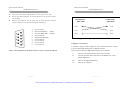
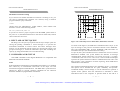
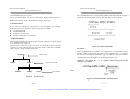
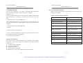
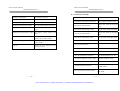
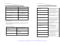
1
Artisan Technology Group is your source for quality
new and certified-used/pre-owned equipment
• FAST SHIPPING AND
DELIVERY
• TENS OF THOUSANDS OF
IN-STOCK ITEMS
• EQUIPMENT DEMOS
• HUNDREDS OF
MANUFACTURERS
SUPPORTED
• LEASING/MONTHLY
RENTALS
• ITAR CERTIFIED
SECURE ASSET SOLUTIONS
SERVICE CENTER REPAIRS
Experienced engineers and technicians on staff
at our full-service, in-house repair center
WE BUY USED EQUIPMENT
Sell your excess, underutilized, and idle used equipment
We also offer credit for buy-backs and trade-ins
www.artisantg.com/WeBuyEquipment
InstraView REMOTE INSPECTION
LOOKING FOR MORE INFORMATION?
Visit us on the web at www.artisantg.com for more
information on price quotations, drivers, technical
specifications, manuals, and documentation
SM
Remotely inspect equipment before purchasing with
our interactive website at www.instraview.com
Contact us: (888) 88-SOURCE | [email protected] | www.artisantg.com
GDM-8246 MULTIMETER
GDM-8246 MULTIMETER
PROGRAMMER MANUAL
CONTENTS
PAGE
1. INTRODUCTION............................................................................. 1
2. CONNECTING DMM VIA GPIB INTERFACE……………... 2
3. CONNECTING DMM VIA RS232 INTERFACE……………. 5
4. INPUT AND OUTPUT QUEUE……………………………….. 8
5. COMMANDS AND SYNTAX…………………………………. 8
PROGRAMMER MANUAL
1. INTRODUCTION
In the modern automatic measurement system, communication
between equipments and computers is essential. The measured
procedures can be varied with user’s testing programs, therefore, the
Digital Multimeter can be operated remotely from an instrument
controller or computer across the RS232 interface (optional) or GPIB
(optional).
6. DETAILS OF COMMAND REFERENCE…………………… 21
Interface selection and setup
7. STATUS AND ERROR REPORTING……………………….... 46
Press [SHIFT][SET] in sequence into SET mode, then press [RS-232] or
[GPIB] the white characters with blue background to set the RS232 OR
GPIB interface. If the indicator of negative sine lights, the value
displayed on the front panel is the current setting value. Use [▲][▼] can
adjust the baud rate (or GPIB address). Finally, press [ENTER] to store
the setup or press [SHIFT] to cancel the setup.
⎯ 1 ⎯
⎯ 1 ⎯
Artisan Technology Group - Quality Instrumentation ... Guaranteed | (888) 88-SOURCE | www.artisantg.com
GDM-8246 MULTIMETER
GDM-8246 MULTIMETER
PROGRAMMER MANUAL
2. CONNECTING THE DIGITAL MULTIMETER VIA
GPIB INTERFACE
The GPIB interface capabilities:
The GPIB interface of the Digital Multimeter corresponds to the
standard of IEEE488.1-1987, IEEE488.2-1992 and SCPI-1994. The
GPIB interface functions are listed as follows:
SH1(Source Handshake)
: The DMM can transmit multilane
messages across the GPIB.
AH1(Acceptor Handshake) : The DMM can receive multilane
messages across the GPIB.
T6(Talker)
: Talker interface function includes basic
talker, serial poll, and unaddress if MLA
capabilities, without talk only mode
function.
L4 (Listener)
: The DMM becomes a listener when the
controller sends its listen address with
the ATN (attention) line asserted. The
DMM does not have listen only
capability.
SR1 (Service Request)
: The DMM asserts the SRQ (Service
request) line to notify the controller
when it requires service.
RL1 (Remote/Local)
: The DMM responds to both the GTL(Go
to Local) and LLO(Local Lock Out)
interface messages.
PP0 (Parallel Poll)
: The DMM has no Parallel Poll interface
function.
DC1 (Device Clear)
: The DMM has Device clear capability to
return the device to power on status.
DT0 (Device Trigger)
: The DMM has no Device Trigger
interface function.
C0 (Controller)
: The DMM can not control other devices.
⎯
2 ⎯
PROGRAMMER MANUAL
Notes for GPIB installation
When the Digital Multimeter is set up with a GPIB system, please check
the following things:
z
Only a maximum of 15 devices can be connected to a single GPIB
bus.
z
Do not use more than 20m of cable to connect devices to a bus.
z
Connect one device for every 2m of cable used.
z
Each device on the bus needs a unique device address. No two
devices can share the same device address.
z
Turn on at least two-thirds of the devices on the GPIB system while
using the system.
z
Do not use loop or parallel structure for the topology of GPIB
system.
Computer’s Connection
A personal computer with a GPIB card is the essential facilities in order
to operate the Digital Multimeter via GPIB interface.
The connections between DMM and computer are following:
I.
Connect one end of a GPIB cable to the computer.
II.
Connect the other end of the GPIB cable to the GPIB port on
the Digital Multimeter.
III.
Turn on the Digital Multimeter.
IV.
Turn on the computer.
⎯
Artisan Technology Group - Quality Instrumentation ... Guaranteed | (888) 88-SOURCE | www.artisantg.com
3 ⎯
GDM-8246 MULTIMETER
GDM-8246 MULTIMETER
PROGRAMMER MANUAL
The GPIB connection testing
If you want to test whether the GPIB connection is working or not, you
can send a GPIB command from computer. For instance, the query
command
*idn?
should return the Manufacturer, model number, and firmware version in
the following format:
PROGRAMMER MANUAL
3. CONNECTING THE DIGITAL MULTIMETER VIA
RS232 INTERFACE
The RS232 interface capabilities:
The RS232 interface provides a point-to-point connection between two
items of equipment such as a computer and the DMM. There are some
parameters you need to set on the both sides. Once you have set these
parameters, you can control the DMM through the RS232 interface.
z
Baud rate: You can set rates of 1200, 2400, 4800 or 9600 baud.
z
Parity bit: none.
z
Data bit: 8 bits.
z
Stop bit: 1 stop bit.
z
Data flow control: none.
GW.Inc,GDM-8246,FW1.00
If you do not receive a proper response from the DMM, please check if
the power is on, the GPIB address is correct, and all cable connections
are active.
Notes for RS232 installation
The DMM is a DTE device with a 9-pin D-type shell RS232 connector
located on the rear panel. Figure 1 shows the equipment of 9-pin
connector (male) with its pin number assignments. Figure 2 shows the
wiring configuration for DB9 to DB9. When the Digital Multimeter is set
up with a RS232 interface, please check the following points:
⎯
4 ⎯
z
Do not connect the output line of one DTE device to the output line
of the other.
z
Many devices require a constant high signal on one or more input
pins.
z
Ensure that the signal ground of the equipment is connected to the
signal ground of the external device.
z
Ensure that the chassis ground of the equipment is connected to the
chassis ground of the external device.
⎯
Artisan Technology Group - Quality Instrumentation ... Guaranteed | (888) 88-SOURCE | www.artisantg.com
5 ⎯
GDM-8246 MULTIMETER
GDM-8246 MULTIMETER
PROGRAMMER MANUAL
z
Do not use more than 15m of cable to connect devices to a PC.
z
Ensure the same baud rate is used on the device as the one used on
PC terminal.
z
Ensure the connector for the both side of cable and the internal
connected line are met the demand of the instrument.
1.
2.
3.
4.
5.
6.
7.
8.
9.
No connection
Receive Data(RxD) (input)
Transmit Data(TxD) (output)
No connection
Signal Ground(GND)
No connection
No connection
No connection
No connection
PROGRAMMER MANUAL
EQUIPMENT
COMPUTER
(DB9, DTE)
(DB9, DTE)
Pin2
Pin2
Pin3
Pin3
Pin5
Pin5
Figure 2 Wiring configuration for DB9 to DB9
Computer’s Connection
A personal computer with a COM port is the essential facilities in order
to operate the Digital Multimeter via RS232 interface.
Figure 1 Pin assignments of the RS232 connector on the rear panel for DB-9-D
⎯
6 ⎯
The connections between DMM and computer are as follows:
I.
Connect one end of a RS232 cable to the computer.
II.
Connect the other end of the cable to the RS232 port on the
Digital Multimeter.
III.
Turn on the Digital Multimeter.
IV.
Turn on the computer.
⎯
Artisan Technology Group - Quality Instrumentation ... Guaranteed | (888) 88-SOURCE | www.artisantg.com
7 ⎯
GDM-8246 MULTIMETER
GDM-8246 MULTIMETER
PROGRAMMER MANUAL
PROGRAMMER MANUAL
The RS232 connection testing
SCPI
If you want to test whether the RS232 connection is working or not, you
can send a command from computer. For instance, using a terminal
program send the query command
Common Command & Queries
*idn?
Syntax & Status Data Structure
should return the Manufacturer, model number, serial number and
firmware version in the following format:
Interface Function
D
GW.Inc,GDM-8246,FW1.00
C
B
A
A
B
C
D
If you do not receive a proper response from the DMM, please check if
the power is on, the RS232 baud rate are the same on both sides, and all
cable connections are active.
4. INPUT AND OUTPUT QUEUE
The design of 128 bytes input queue and 128 bytes output queue for
storing the pending commands or return messages is to prevent the
transmitted commands of remote control and return messages from
missing. As the maximum stored capacity for Error/Event Queue is 20
groups of messages, it should be noted that input data exceeding the
capacity by using these buffers will cause data missing.
5. COMMANDS AND SYNTAX
The GPIB commands of the Digital Multimeter are compatible with
IEEE-488.2 and SCPI standards
SCPI
SCPI (Standard Commands for Programmable Instruments) is a standard
that created by an international consortium of the major test and
measurement equipment manufacturers. The IEEE-488.2 syntax has been
adopted by SCPI to provide common commands for the identical
functions of different programmable instruments.
⎯
8 ⎯
SCPI
IEEE-488.2
IEEE-488.1
SCPI
IEEE-488.2
Figure 3 the relationship between IEEE-488.1, IEEE-488.2, and SCPI
As shown in the figure 3, the IEEE-488.1 standard locates at layer A, the
layer A belongs to the protocol of interface function on the GPIB bus.
The source handshake (SH), acceptor handshake (AH) and talker are
included to this layer (10 interface functions totally).
At layer B, the syntax and data structure could be the essence of entire
IEEE-488.2 standard. The syntax defines the function of message
communication, which contain the <PROGRAM MESSAGE> (or simply
“commands”) and <RESPONSE MESSAGE>. The two kinds of messages
represent the syntax formation of device command and return value. The
data structure is the constitution of status reporting, which IEEE-488.2
standard have been defined.
The common commands and queries are included to layer C. Commands
and queries can be divided into two parts: mandatory and optional.
Commands modify control settings or tell the instrument to perform a
specific action. Queries cause the instrument to send data or status
information back to the computer. A question mark at the end of a
⎯
Artisan Technology Group - Quality Instrumentation ... Guaranteed | (888) 88-SOURCE | www.artisantg.com
9 ⎯
GDM-8246 MULTIMETER
GDM-8246 MULTIMETER
PROGRAMMER MANUAL
PROGRAMMER MANUAL
command identifies it as a query.
The command header is configured by header path and leaf node. Figure 5
shows the command header for the leaf node indicated in Figure 4.
Layer D is interrelated with device information. Different devices have
different functions. SCPI command sets belong to this layer.
Command Syntax
If you want to transfer any instructions to an instrument, and comply
with SCPI, there are three basic elements must be included.
z
z
z
Command header
Parameter (if required)
Message terminator or separator
Command Header
The command header has a hierarchical structure that can be represented
by a command tree (Figure 4).
The top level of the tree is the root level. A root node is located at the
root level. A root node and one or more lower-level nodes form a header
path to the last node called the leaf node.
:SYSTem
:ERRor
Figure 5 Command Header
Parameter
If the commands have parameters, the values have to be included. In this
manual, when we expressed the syntax of the command, the < > symbols
are used for enclosing the parameter type. For instance, the syntax of the
command in Figure 6 includes the Boolean parameter type.
Root node
NOTE: Do not include the <, >, or | symbols when entering the actual
value for a parameter.
Lower-level node
:AUTO
Leaf
:STATe
:STARt
:CYCLe
Leaf Node
Figure 4: Tree hierarchy
Figure 6 Command Header with Parameter
⎯ 10 ⎯
⎯
Artisan Technology Group - Quality Instrumentation ... Guaranteed | (888) 88-SOURCE | www.artisantg.com
11 ⎯
GDM-8246 MULTIMETER
GDM-8246 MULTIMETER
PROGRAMMER MANUAL
PROGRAMMER MANUAL
Table 1 defines the Boolean and other parameter types for the Digital
Multimeter.
Parameter Type
Description
Example
0, 1
Boolean
Boolean numbers or
values
NR1
Integers
0, 1, 18
NR2
Decimal numbers
1.5, 3.141, 8.4
NR3
Floating point numbers
4.5E-1, 8.25E+1
String
Alphanumeric characters
“No error”
Table 1: Parameter Types for Syntax Descriptions
Message Terminator and Message Separator
I. GPIB message terminators
In accordance with IEEE 488.2 standard, any of the following message
terminators are acceptable:
z
LF^END
Line feed code (hexadecimal 0A) with END
message
z
LF
Line feed code
z
^
<dab> END
II. RS232 message terminators
As there is no signal of end message on RS232 bus, therefore, use LF
as message terminator. When a series of commands are sent to the
instrument, it must add a LF to be a judgment for message terminator.
As for query command, the return message of the instrument is also
added a LF for PC to judge message terminator.
Entering Commands
The standards that govern the command set for the Digital Multimeter
allow for a certain amount of flexibility when you enter commands. For
instance, you can abbreviate many commands or combine commands
into one message that you send to the Digital Multimeter. This
flexibility, called friendly listening, saves programming time and makes
the command set easier to remember and use.
Command Characters
The DMM is not sensitive to the case of command characters. You can
enter commands in either uppercase or lowercase.
You can execute any command with white space characters. You must,
however, use at least one space between the parameter and the command
header
Abbreviating Commands
Last data byte with END message
These terminators are compatible with most application programs. A
semicolon separates one command from another when the commands
appear on the same line.
Most commands have a long form and a short form. The listing for
each command in this section shows the abbreviations in uppercase.
For instance, you can enter the query :CONFigure:VOLTage:DC 0
simply as :CONF:VOLT:DC 0
Because the Digital Multimeter hypothesis that a command starts from
the root, you have the option of beginning the initial command header
with a colon (:).
⎯ 12 ⎯
⎯
Artisan Technology Group - Quality Instrumentation ... Guaranteed | (888) 88-SOURCE | www.artisantg.com
13 ⎯
GDM-8246 MULTIMETER
GDM-8246 MULTIMETER
PROGRAMMER MANUAL
PROGRAMMER MANUAL
z General Setting Commands
Combining Commands
You can use a semicolon (;) to combine commands. But continuously
query command will cause message missing. For example:
:READ?;:VAL?
Table 2 lists the general setting commands that control and query the
settings of the DMM.
If the command that follows the semicolon has a different header path
from the root level, you must use a colon to force a return to the root
level:
Table 2: General Setting Commands
:CONF:VOLT:DC 0;:CALC:SDBM:STAT 1
:CONFigure:AUTo?
Returns Auto-range mode on or off.
If the command that follows the semicolon has the same header path, you
may omit the colon and the path and state only the new leaf node. For
example:
:CONFigure:AUTo <Beolean>
Sets Auto-range mode on or off.
:CONFigure:RANGe?
Returns the range of the present
function.
:CONFigure:MODe?
Returns the total value of the
selected calculation mode.
:CONFigure:FUNCtion?
Returns the present selected
function.
:CONFigure:CAPacitance <NR2>
Sets capacitance function and range.
:CONFigure:CONTinuity
Sets continuity function.
:CONFigure:CURRent:AC <NR2>
Sets AC current function and range.
:CONFigure:CURRent:DC <NR2>
Sets DC current function and range.
: CONF:VOLT:DC 0;:CONF:CURR:DC 0
Command
Explanation
is equal to
: CONF:VOLT:DC 0;:CURR:DC 0
You can combine commands and queries into the same message. Note,
for example, the following combination:
: CONF:VOLT:DC 0;:READ?
Synopsis of Commands
The tables in this section summarize the command of the Digital
Multimeter. These tables divide the commands into four functional
classifications:
:CONFigure:CURRent:ACDC <NR2> Sets AC+DC current function and
range.
:CONFigure:DIODe
Sets diode function.
z
General Setting Commands
Calculating Commands.
z
Status Commands
z
Miscellaneous Commands
The tables also provide a brief explanation of each command.
z
⎯ 14 ⎯
⎯
Artisan Technology Group - Quality Instrumentation ... Guaranteed | (888) 88-SOURCE | www.artisantg.com
15 ⎯
GDM-8246 MULTIMETER
GDM-8246 MULTIMETER
PROGRAMMER MANUAL
PROGRAMMER MANUAL
z Calculation Commands
:CONFigure:SFRequency
Sets frequency function.
:CONFigure:RESistance <NR2>
Sets resistance function and range.
:CONFigure:VOLTage:AC <NR2>
Sets AC voltage function and range.
:CONFigure:VOLTage:DC <NR2>
Sets DC voltage function and range.
:CALCulation: LIMit:STATe?
Returns Compare mode on or off.
:CALCulation: LIMit:STATe <Boolean>
Sets Compare mode on or off.
:CALCulation: LIMit:LOWer?
Returns the value of the lower
limit.
:CONFigure:VOLTage:ACDC <NR2> Sets AC+DC voltage function and
range.
:CALCulation: LIMit:LOWer <NR2>
Sets the value of the lower limit.
:CONFigure:VOLTage:DCAC <NR2> Sets Ripple voltage function and
range.
:CALCulation: LIMit:UPPer?
Returns the value of the upper
limit.
:CALCulation: LIMit:UPPer <NR2>
Sets the value of the upper limit.
:READ?
Returns the value displayed on the
primary and secondary display
:VALue?
Returns the value displayed on the
primary display.
:CALCulation: LIMit:FAIL?
Returns the limit result.
:SVALue?
Returns the value displayed on the
secondary display.
:CALCulation:MAXimum?
Returns the MAX mode on or
off.
:CALCulation:MAXimum <Boolean>
Sets the MAX mode on or off.
:CALCulation:MINimum?
Returns the MIN mode on or off.
:CALCulation:MINimum <Boolean>
Sets the MIN mode on or off.
:CALCulation: RELation: STATe <NR1> Sets REL mode on or off.
⎯ 16 ⎯
:CALCulation:RELation: STATe?
Returns REL mode on or off.
:CALCulation:RELation:DATa?
Returns the reference value of
the REL mode.
:CALCulation:RELation:DATa <NR2>
Sets the reference value of the
REL mode.
⎯
Artisan Technology Group - Quality Instrumentation ... Guaranteed | (888) 88-SOURCE | www.artisantg.com
17 ⎯
GDM-8246 MULTIMETER
GDM-8246 MULTIMETER
PROGRAMMER MANUAL
PROGRAMMER MANUAL
Returns DBM mode on or off.
:CALCulation:SDMB:STATe?
:CALCulation: SDMB:STATe <Boolean> Sets DBM mode on or off.
*SRE <NR1>
Sets contents of Service Request
Enable Register (SRER).
:CALCulation: SDMB:REFerence?
Returns the reference impedance
value of the DBM mode.
*SRE?
Returns contents of Service
Request Enable Register (SRER).
:CALCulation: SDMB:REFerence <NR1>
Sets the reference impedance
value of the DBM mode.
*STB?
Reads Status Byte Register
(SBR).
Returns the hold and auto-hold
on or off.
:STATus:OPERation:CONDition?
:CALCulation:HOLD?
Returns the contents of the
OPERation condition register. Returns
NR1.
:CALCulation:HOLD <NR1>
Sets the hold and auto-hold on or
off.
:STATus:OPERation:ENABle
<NR1>
Sets the contents of the enable mask
for the OPERation event register.
:STATus:OPERation:ENABle?
Returns the contents of the enable
mask for the OPERation event
register. Returns NR1.
:STATus:OPERation:EVENt?
Query the contents of the OPERation
Event register.
:STATus:PRESet
Presets the OPERation and
QUEStionable status registers.
z Status Commands
Table 3 lists the status commands that set and query the various
registers and queues that make up the status and event structure of
the Digital Multimeter.
Table 3: Status Commands
*CLS
Clears the status data structures.
*ESE <NR1>
Sets the Event Status Enable Register
(ESER).
*ESE?
Returns contents of Event Status Enable
Register (ESER).
*ESR?
Returns and clear the contents of
Standard Event Status Register (SESR).
⎯ 18 ⎯
:STATus:QUEStionable:CONDition? Returns the contents of the
OPERation condition register. Returns
NR1.
:STATus:QUEStionable:ENABle
<NR1>
Sets the contents of the enable mask
for the QUEStionable enable register.
:STATus:QUEStionable:ENABle?
Query the contents of the
Questionable Enable register.
:STATus:QUEStionable:EVENt?
Query the contents of the
QUEStionable Event register.
⎯
Artisan Technology Group - Quality Instrumentation ... Guaranteed | (888) 88-SOURCE | www.artisantg.com
19 ⎯
GDM-8246 MULTIMETER
GDM-8246 MULTIMETER
PROGRAMMER MANUAL
z Miscellaneous Commands
6. DETAILS OF COMMAND REFERENCE
Table 4 lists the miscellaneous commands that control general
housekeeping functions of the Digital Multimeter.
Table 4: Miscellaneous Commands
Returns instrument identification.
*OPC
Reports when operation is completed by
setting the Operation Complete bit in SESR.
*OPC?
Reports when operation is completed. Same as
*OPC except returns a 1 to the output queue
and dose not set the SESR bit.
*WAI
Each command in this chapter will give a detailed description. The
examples of each command will be provided and what query form might
return.
*CLS (no query form)
*IDN?
*RST
PROGRAMMER MANUAL
Resets the protection levels and states, resets
the current and voltage levels to zero, sets the
output off, and sets memory section to 00.
Wait to continue. This command forces
sequential operation of commands. This
command is required by IEEE-488.1-1987.
The DMM, however, forces sequential
operation of commands by design.
Function:
Clear all event status data register. This includes the Output Queue,
Operation Event Status Register, Questionable Event Status Register, and
Standard Event Status Register.
Syntax:
*CLS
Examples:
*CLS clears all event registers.
*ESE
:SYSTem:ERRor?
Read the next item from the error/event queue.
Function:
Set or return the bits in the Event Status Enable Register (ESER). The
ESER enables the Standard Event Status Register (SESR) to be
summarized on bit 5 (ESB) of the Status Byte Register (SBR).
:SYSTem:VERSion?
Returns the SCPI version level.
Syntax:
*ESE <NR1>
*ESE?
<NR1> is in the range from 0 through 255.
Returns:
<NR1> is a number from 0 to 255 that indicates the decimal value of the
binary bits of the ESER.
⎯ 20 ⎯
⎯
Artisan Technology Group - Quality Instrumentation ... Guaranteed | (888) 88-SOURCE | www.artisantg.com
21 ⎯
GDM-8246 MULTIMETER
GDM-8246 MULTIMETER
PROGRAMMER MANUAL
PROGRAMMER MANUAL
Examples:
Examples:
*ESE 65 sets the ESER to binary 0100 0001.
If the ESER contains the binary value 1000 0010, the *ESE? will return
the value of 130.
*IDN? Returns GW_Inc, GDM-8246, FW1.00
*OPC
Function:
Return and clear the contents of the Standard Event Status Register
(SESR).
Function:
The command form (*OPC) sets the operation complete bit (bit 0) in the
Standard Event Status Register (SESR) when all pending operations are
finished.
The query form (*OPC?) tells the Digital Multimeter to place an ASCII 1
in the Output Queue when the DMM completes all pending operations.
Syntax:
Syntax:
*ESR?
*OPC
*OPC?
*ESR? (query only)
Returns:
<NR1> is a number from 0 to 255 that indicates the decimal value of the
binary bits of the ESER.
Returns:
1
Examples:
If the ESER contains the binary value 1100 0110, the *ESR? will return
the value of 198.
*IDN? (query only)
Function:
Return the unique identification code of the DMM.
Syntax:
*IDN?
Returns:
<string> includes Manufacturer, model number, serial number and
firmware version.
*RST (no query form)
Function:
Set all control settings of DMM to 1000V DCV range but does not purge
stored setting. The equivalent panel control will be set as below:
*SRE
Function:
Set the contents of the Service Request Enable Register (SRER). The
query form returns the contents of the SRER. Bit 6 of the SRER is
always zero. The bits on the SRER correspond to the bits on the SBR.
Syntax:
*SRE <NR1>
⎯ 22 ⎯
⎯
Artisan Technology Group - Quality Instrumentation ... Guaranteed | (888) 88-SOURCE | www.artisantg.com
23 ⎯
GDM-8246 MULTIMETER
GDM-8246 MULTIMETER
PROGRAMMER MANUAL
PROGRAMMER MANUAL
*SRE?
:CONFigure:AUTo
Returns:
Function:
Set or query the auto-range mode on or off.
<NR1> is in the range from 0 through 255.
Syntax:
Examples
*SRE 7 sets bits of the SRER to 0000 0111.
If the *SRE? returns 3, the SRER is set to 0000 0011.
:CONFigure:AUTo?
:CONFigure:AUTo <Boolean>
<Boolean> can be 0(off) or 1(on)
*STB? (query only)
Returns:
Function:
The query of the Status Byte register (SBR) with *STB? will return a
decimal number representing the bits that are set (true) in the status
register.
Syntax:
0/1
Examples:
:CONFigure:AUTo 1
Set to auto-range mode.
*STB?
If it is in the auto-range mode, the command of :CONFigure:AUTo? Will
return the value of 1.
Returns:
<NR1> is in the range from 0 through 255.
Examples:
*STB? returns 81, if SBR contains the binary value 0101 0001.
*WAI (no query form)
Function:
WAI prevents the programming instrument from executing further
commands or queries until all pending operations are finished.
Syntax:
:CONFigure:RANGe?(query only)
Function:
Set or query the range of the present function.
Syntax:
:CONFigure:RANGe?
Returns:
<NR2>
*WAI
⎯ 24 ⎯
⎯
Artisan Technology Group - Quality Instrumentation ... Guaranteed | (888) 88-SOURCE | www.artisantg.com
25 ⎯
GDM-8246 MULTIMETER
GDM-8246 MULTIMETER
PROGRAMMER MANUAL
PROGRAMMER MANUAL
Examples:
Table 6-2:
:CONFigure:RANGe? might return 50.000 to indicate the 50V range at
DCV.
Calculation Function
MIN
MAX
HOLD
AUTOHOLD
dBm
REL
COMP
Please refer to the representative unit for every function range as follows:
Table 6-1:
Voltage
V
Capacitance
nF
Current
mA
Diode
V
Resistance
kohm
Continuity
kohm
Frequency
kHz
dBm
dBm
Corresponding Value
1
2
4
8
16
32
64
:CONFigure:FUNCtion?(query only)
Function:
Return the present selected function.
:CONFigure:MODe?(query only)
Syntax:
Function:
:CONFigure:FUNCtion?
Return the total value of the selected calculation mode.
Returns:
Syntax:
String
:CONFigure:MODe?
Examples:
Returns:
<NR1> is in the range from 0 through 255.
:CONFigure:FUNCtion? might return “DCV” to indicate the present DC
voltage function.
Examples:
Please refer to the returned message for every function as follows:
:CONFigure:MODe? might return 1 to indicate the MIN mode to be
slected.
Table 6-3:
Please refer to the representative total value for every attached
calculation mode as follows:
⎯ 26 ⎯
Function
DC Voltage
AC Voltage
AC+DC Voltage
ACV + Frequency
Description
DCV
ACV
AC+DCV
Hz+ACV
⎯
Artisan Technology Group - Quality Instrumentation ... Guaranteed | (888) 88-SOURCE | www.artisantg.com
27 ⎯
GDM-8246 MULTIMETER
GDM-8246 MULTIMETER
PROGRAMMER MANUAL
DC Current
AC Current
AC+DC Current
ACA + Frequency
Resistance
Capacitance
Diode
Continuity
Ripple
DCA
ACA
AC+DCA
Hz+ACA
OHM
CAPACITANCE
DIODE
CONT
RIPPLE
PROGRAMMER MANUAL
Examples:
:CONFigure:CONTinity sets the continuity function.
Please refer to the Table 6-1.
:CONFigure:CURRent:DC <NR2>
Function:
Set the DC current function and range.
Syntax:
:CONFigure:CAPacitance
:CONFigure:CURRent:DC <NR2>
Function:
Set capacitance function and the range.
Examples:
:CONFigure:CURRent:DC 0 sets the DC current function and
auto-range.
:CONFigure:CURRent:DC 1.5 sets the DC current function and 50mA
range.
Syntax:
:CONFigure:CAPacitance <NR2>
Examples:
Please refer to the unit for every range shown as Table 6-1.
:CONFigure:CAPacitance 0 sets to capacitance function and auto-range.
:CONFigure:CAPacitance 30 sets to capacitance function and 30nF
range.
:CONFigure:CURRent:AC <NR2>
Please refer to the unit for every range shown as Table 6-1.
Function:
Set the AC current function and range.
Syntax:
:CONFigure:CONTinuity
Function:
:CONFigure:CURRent:AC <NR2>
Examples:
Set the continuity function
:CONFigure:CURRent:AC 0 sets the AC current function and
auto-range.
:CONFigure:CURRent:AC 1.5 sets the AC current function and 50mA
range.
Syntax:
:CONFigure:CONTinity
⎯ 28 ⎯
⎯
Artisan Technology Group - Quality Instrumentation ... Guaranteed | (888) 88-SOURCE | www.artisantg.com
29 ⎯
GDM-8246 MULTIMETER
GDM-8246 MULTIMETER
PROGRAMMER MANUAL
Please refer to the unit for every range shown as Table 6-1.
:CONFigure:CURRent:ACDC <NR2>
PROGRAMMER MANUAL
Set the frequency function in the AC mode.
Syntax:
:CONFigure:SFRequency
Function:
Set the AC+DC current function and range.
Examples:
Syntax:
:CONFigure:SFRequency sets the frequency function.
:CONFigure:CURRent:ACDC <NR2>
Examples:
:CONFigure:RESistance <NR2>
:CONFigure:CURRent:ACDC 0 sets the AC+DC current function and
auto-range.
:CONFigure:CURRent:ACDC 1.5 sets the AC+DC current function
and 50mA range.
Function:
Syntax:
Please refer to the unit for every range shown as Table 6-1.
:CONFigure:RESistance <NR2>
Set the resistance function and range.
Examples:
:CONFigure:RESistance 0 sets the resistance function and auto-range.
:CONFigure:RESistance 39 sets the resistance function and 50 ohm
range.
:CONFigure:DIODe
Function:
Set the DC diode function.
Please refer to the unit for every range shown as Table 6-1.
Syntax:
:CONFigure:DIODe
Examples:
:CONFigure:VOLTage:DC <NR2>
:CONFigure:DIODe sets diode function.
Function:
Please refer to the unit for every range shown as Table 6-1.
Set the DC voltage function and range.
Syntax:
:CONFigure:VOLTage:DC <NR2>
:CONFigure:SFRequency
Function:
Examples:
:CONFigure:VOLTage:DC 0 sets the DC voltage function and auto-range.
⎯ 30 ⎯
⎯
Artisan Technology Group - Quality Instrumentation ... Guaranteed | (888) 88-SOURCE | www.artisantg.com
31 ⎯
GDM-8246 MULTIMETER
GDM-8246 MULTIMETER
PROGRAMMER MANUAL
:CONFigure: VOLTage:DC 12 sets the DC voltage function and 50V
range.
PROGRAMMER MANUAL
and 50V range.
Please refer to the unit for every range shown as Table 6-1.
Please refer to the unit for every range shown as Table 6-1.
:CONFigure:VOLTage:DCAC <NR2>
:CONFigure:VOLTage:AC <NR2>
Function:
Function:
Set the DCAC voltage function and range.
Set the AC voltage function and range.
Syntax:
Syntax:
:CONFigure:VOLTage:DCAC <NR2>
:CONFigure:VOLTage:AC <NR2>
Examples:
Examples:
:CONFigure:VOLTage:AC 0 sets the AC voltage function and
auto-range.
:CONFigure: VOLTage:AC 12 sets the AC voltage function and 50V
range.
:CONFigure:VOLTage:DCAC 0 sets the Ripple voltage function and
auto-range.
:CONFigure: VOLTage:DCAC 41 sets the Ripple voltage function and
50V range.
Please refer to the unit for every range shown as Table 6-1.
Please refer to the unit for every range shown as Table 6-1.
:CONFigure:VOLTage:ACDC <NR2>
Function:
Set the ACDC voltage function and range.
Syntax:
:CONFigure:VOLTage:ACDC <NR2>
Examples:
:CONFigure:VOLTage:ACDC 0 sets the AC+DC voltage function and
auto-range.
:CONFigure: VOLTage:ACDC 12.5 sets the AC+DC voltage function
⎯ 32 ⎯
⎯
Artisan Technology Group - Quality Instrumentation ... Guaranteed | (888) 88-SOURCE | www.artisantg.com
33 ⎯
GDM-8246 MULTIMETER
GDM-8246 MULTIMETER
PROGRAMMER MANUAL
PROGRAMMER MANUAL
:READ?(query only)
Syntax:
Function:
:SVALue?
Returns the value displayed on the primary and secondary display with
14 characters totally.
Examples:
Syntax:
:SVALue? might return “ -OL- ” when the current function is in the dBm
mode.
:READ?
:CALCulation:LIMit:STATe
Examples:
:READ? Might return “ NONE ,+0.0000” when the current function is in
the DC voltage.
Function:
Returns or sets the compare mode on or off.
Syntax:
:VALUE?(query only)
:CALCulation:LIMit:STATe?
Function:
:CALCulation:LIMit:STATe <Boolean>
Returns the value displayed on the primary and secondary display with 7
characters totally.
<Boolean> can be o(off) or 1(on)
Returns:
Syntax:
0/1
:VALUE?
Examples:
Examples:
:VALUE? might return “+0.0000” when the current function is in the DC
voltage.
:CALCulation:LIMit:STATe? might return 1 in the compare mode.
:CALCulation:LIMit:STATe 1 sets the compare mode.
:SVALue?(query only)
:CALCulation:LIMit:LOWer
Function:
Function:
Returns the value displayed on the primary and secondary display with 6
Returns or sets the value of the lower limit in the compare mode.
characters totally.
Syntax:
⎯ 34 ⎯
⎯
Artisan Technology Group - Quality Instrumentation ... Guaranteed | (888) 88-SOURCE | www.artisantg.com
35 ⎯
GDM-8246 MULTIMETER
GDM-8246 MULTIMETER
PROGRAMMER MANUAL
PROGRAMMER MANUAL
:CALCulation:LIMit:LOWer?
:CALCulation:LIMit:FAIL?
:CALCulation:LIMit:LOWer <NR2>
Examples:
Examples:
0(low)/1(pass)/2(high)
:CALCulation:LIMit:LOWer? might return +1.0000 in the DC voltage
function.
:CALCulation:LIMit:FAIL? might return 1 means the reading is pass.
:CALCulation:LIMit:LOWer 1.0000 sets 1.0000 DC voltage at the lower
limit in the DC voltage function.
:CALCulation:MAXimum
Function:
Returns or sets the MAX mode on or off.
:CALCulation:LIMit:UPPer
Syntax:
Function:
Returns or sets the value of the upper limit in the compare mode.
:CALCulation:MAXimum?
:CALCulation:MAXimum <Boolean>
Syntax:
<Boolean> can be o(off) or 1(on).
:CALCulation:LIMit:UPPer?
Examples:
:CALCulation:LIMit:UPPer <NR2>
:CALCulation:MAXimum? might return 1 in the MAX mode.
Examples:
:CALCulation:LIMit:UPPer? might return +1.0000 in the DC voltage
function.
:CALCulation:LIMit:UPPer 1.0000 sets 1.0000 DC voltage at the upper
limit in the DC voltage function.
:CALCulation:MAXimum 1 sets the MAX mode.
:CALCulation:MINimum
Function:
:CALCulation:LIMit:FAIL?
Returns or sets the MIN mode on or off.
Syntax:
Function:
:CALCulation:MINimum?
Returns limit result.
:CALCulation:MINimum
<Boolean>
Syntax:
⎯ 36 ⎯
⎯
Artisan Technology Group - Quality Instrumentation ... Guaranteed | (888) 88-SOURCE | www.artisantg.com
37 ⎯
GDM-8246 MULTIMETER
GDM-8246 MULTIMETER
PROGRAMMER MANUAL
PROGRAMMER MANUAL
<Boolean> can be o(off) or 1(on).
Examples:
Examples:
:CALCulation:RELation:DATa? might return +1.0000 in DC voltage
function.
:CALCulation:MINimum? might return 1 in the MIN mode.
:CALCulation:MINimum 1 sets the MIN mode.
:CALCulation:RELation:DATa 1.0000 sets 1.0000 DC voltage at the
reference standard value.
Please refer to the unit for every range shown as Table 6-1.
:CALCulation:RELation:STATe
Function:
:CALCulation:SDBM:STATe
Returns or sets the REL mode on or off.
Function:
Syntax:
Returns or sets the SDBM mode on or off.
:CALCulation:RELation:STATe?
Syntax:
:CALCulation:RELation:STATe <Boolean>
<Boolean> can be o(off) or 1(on).
:CALCulation:SDBM:STATe?
:CALCulation:SDBM:STATe <Boolean>
Examples:
<Boolean> can be o(off) or 1(on).
:CALCulation:RELation:STATe? might return 1 in the REL mode.
:CALCulation:RELation:STATe 1 sets the REL mode.
Examples:
:CALCulation:SDBM:STATe? might return 1 in the dBm mode.
:CALCulation:SDBM:STATe 1 sets the dBm mode.
:CALCulation:RELation:DATa
Function:
:CALCulation:REFerence:SDBM:REFerence
Returns or sets the reference value in the REL mode.
Syntax:
Function:
Returns or sets the reference impedance in the dBm mode.
:CALCulation:RELation:DATa?
:CALCulation:RELation: DATa <NR2>
⎯ 38 ⎯
Syntax:
:CALCulation:SDBM:REFerence?
⎯
Artisan Technology Group - Quality Instrumentation ... Guaranteed | (888) 88-SOURCE | www.artisantg.com
39 ⎯
GDM-8246 MULTIMETER
GDM-8246 MULTIMETER
PROGRAMMER MANUAL
PROGRAMMER MANUAL
:CALCulation: SDBM:REFerence <NR1>
:CALCulation:HOLD 1 sets the Hold mode.
Examples:
:CALCulation:SDBM:REFerence? might return 0600 in DC voltage
function.
STATus:OPERation:CONDition? (query only)
:CALCulation: SDBM:REFerence 600 sets 600 ohm DC voltage at the
reference standard value.
Function:
Return the contents of the OPERation register. The DMM, however, do
not use the OPERation register to report any conditions.
Please refer to the unit for every range shown as Table 6-4:
Syntax:
STATus:OPERation:CONDition?
Table 6-4:
Selectable Reference Impedance in ohms:
2
93
4
110
8
124
16
125
50
135
75
150
Returns:
250
300
500
600
800
900
:CALCulation:HOLD
Function:
Returns or sets the Hold and Auto-hold mode on or off.
Syntax:
1000
1200
8000
<NR1>
Examples:
STATus:OPERation:CONDition? returns 0.
STATus:OPERation:ENABle
Function:
Set or query the enable mask that allows the masked conditions in the
event register to be reported in the summary bit. If a bit is 1 (true) in the
enable register and its associated event bit changes to 1 (true), the
associated summary bit will change to 1 (true). Even though this is a
16-bit register, only 15 bits (bit 0 through bit 14) are used. Bit 15 always
reads 0.
Syntax
:CALCulation:HOLD?
STATus:OPERation:ENABle <NR1>
STATus:OPERation:ENABle?
:CALCulation:HOLD <Boolean>
<Boolean> can be o(off), 1(hold),or 2(auto-hold).
Examples:
<NR1> is an integer from 0 to 32767.
Returns
:CALCulation:HOLD? might return 2 in the Auto-hold mode.
⎯ 40 ⎯
<NR1>
⎯
Artisan Technology Group - Quality Instrumentation ... Guaranteed | (888) 88-SOURCE | www.artisantg.com
41 ⎯
GDM-8246 MULTIMETER
GDM-8246 MULTIMETER
PROGRAMMER MANUAL
Examples
PROGRAMMER MANUAL
Syntax:
STATus:OPERation:ENABle 32767 sets all 15 bits of the register to 1.
If the STATus:OPERation:ENABle? returns 0, all 15 bits of the register
are 0.
STATus:QUEStionable:CONDition?
Returns:
<NR1>
STATus:OPERation:EVENt (query only)
Examples:
Function:
Returns and clears the contents of the OPERation register.
STATus:QUEStionable:CONDition? returns 0.
Syntax:
STATus:QUEStionable:ENABle
STATus:OPERation:EVENt?
Function:
Set or query the enable mask that allows the masked conditions in the
event register to be reported in the summary bit. If a bit is 1 (true) in the
enable register and its associated event bit changes to 1 (true), the
associated summary bit will change to 1 (true). Even though this is a
16-bit register, only 15 bits (bit 0 through bit 14) are used. Bit 15 always
reads 0.
Returns:
<NR1>
Examples:
STATus:OPERation:EVENt? returns 0.
Syntax:
STATus:PRESet
Function:
Set the OPERation and QUESTionable enable registers to zeros.
STATus:QUEStionable:ENABle <NR1>
STATus:QUEStionable:ENABle?
<NR1> is an integer from 0 to 32767.
Syntax:
Returns:
STATus:PRESet
<NR1>
Examples:
STATus:QUEStionable:CONDition? (query only)
Function:
Return the contents of the QUEStionable register. Reading the condition
register is non-destructive.
⎯ 42 ⎯
STATus:QUEStionable:ENABle 32767 sets all 15 bits of the register to
1.
If the STATus:QUEStionable:ENABle? returns 0, all 15 bits of the
register are 0.
⎯
Artisan Technology Group - Quality Instrumentation ... Guaranteed | (888) 88-SOURCE | www.artisantg.com
43 ⎯
GDM-8246 MULTIMETER
GDM-8246 MULTIMETER
PROGRAMMER MANUAL
PROGRAMMER MANUAL
STATus:QUEStionable:EVENt(query only)
SYSTem:VERSion? (query only)
Function:
Return and clear the contents of the QUEStionable register. The response
is a decimal value that summarizes the binary values of the set bits.
Function:
Return the SCPI version of the device.
Syntax:
Syntax:
SYSTem:VERSion?
STATus:QUEStionable:EVENt?
Returns:
Returns:
1994.0
<NR1>
Examples:
STATus:QUEStionable:EVENt? returns 0.
SYSTem:ERRor? (query only)
Function:
Query the next error message from the Error/Event queue. The result of
the query is the error number followed by the error text.
Syntax:
SYSTem:ERRor?
Returns:
<string>
Examples:
SYSTem:ERRor? returns 0, “No error”
⎯ 44 ⎯
⎯
Artisan Technology Group - Quality Instrumentation ... Guaranteed | (888) 88-SOURCE | www.artisantg.com
45 ⎯
GDM-8246 MULTIMETER
GDM-8246 MULTIMETER
PROGRAMMER MANUAL
7.
PROGRAMMER MANUAL
STATUS AND ERROR REPORTING
QUEStionable Status
A set of status registers allows the user to quickly determine the
DMM’s internal processing status. The status register, as well as the
status and event reporting system, adhere to SCPI recommendations.
Structure of System
The sketch of the status and event reporting system is showed as
figure 7. Each component of the sketch represents a set of registers and
queues that can read, report, or enable the occurrence of certain events
within the system.
If a specific event in the DMM sets a bit in a status register, reading
which can tell you what types of events have occurred.
Each bit in the status register corresponds to a bit in an enable register;
the enable bit must be high for the event to be reported to the Status Byte
Register.
A Service Request (SRQ) is the last event to occur. The SRQ requests an
interrupt on the GPIB to report events to the system controller.
Voltage Overload
Current Overload
Not Used
Not Used
Not Used
Frequency Null Sense
Not Used
Not Used
Not Used
Ohm Overload
Capacitance Overload
Limit Test Fail LO
Limit Test Fail HI
Not Used
Not Used
Not Used
0
1
2
3
4
5
6
7
8
9
10
11
12
13
14
15
Error/Event Queue
OPERation Status
Not
Not
Not
Not
Not
Not
Not
Not
Not
Not
Not
Not
Not
Not
Not
Not
Used
Used
Used
Used
Used
Used
Used
Used
Used
Used
Used
Used
Used
Used
Used
Used
0
1
2
3
4
5
6
7
8
9
10
11
12
13
14
15
Output Queue
Status Registers
There are two kinds of status registers are included to the DMM.
z
OPERation Status Registers ( CONDition, EVENt, and ENABle)
z
QUEStionable Status Registers (CONDition, EVENt, and ENABle)
The lower level nodes: QUEStionable and OPERation each have three 16
bits registers: CONDition, EVENt, and ENABle. Figure 8 shows the
sequential relationship between these three types of registers and the
commands that relate to each register.
Standard Event Status Registers
Operation Complete
0
Not Used
Query Error
Device Dependent
Error
Execution Error
Command Error
User
Request
Power On
1
Status Byte Register
Not Used
Not Used
E/E
QUES
MA
V
ESB
RQS/MSS
OPER
2
3
4
5
6
7
0
1
2
3
SRQ
4
5
6
7
Summary of IEEE 488.2 Status Structure Registers
Figure 7. A graphic representation of the status registers and their connections.
⎯ 46 ⎯
⎯
Artisan Technology Group - Quality Instrumentation ... Guaranteed | (888) 88-SOURCE | www.artisantg.com
47 ⎯
GDM-8246 MULTIMETER
GDM-8246 MULTIMETER
PROGRAMMER MANUAL
PROGRAMMER MANUAL
Table 4: QUEStionable Status Register
To SBR
Bit 15 Bit 14
∗
Condition
Register
Event
Register
Bit 13
NU
NU
Bit 7 Bit 6
Bit 5
Enable
Register
NU
NU Frequency
Null Sense
Bit 12
Bit 11
Bit 10
Bit 9
Bit 8
Limit Test Limit Test Capacitance Ohm
Fail HI
Fail LO Overload Overload
Bit 4
Bit 3
Bit 2
NU
NU
NU
Bit 1
NU
Bit 0
Current
Voltage
Overload Overload
Figure 8: Status registers and related commands
The CONDition register is a read-only register which monitors the
present state of the instrument. The CONDition register updates in real
time and the inputs are not latched or buffered. When a condition
monitored by the CONDition register becomes true, the bit for that
condition also becomes true (1). When the condition is false, the bit is 0.
The read-only EVENt register latches any false-to-true change in
condition. Once the bit in the EVENt register is set, it is no longer
affected by changes in the corresponding bit of the CONDition register.
The bit remains set until the controller reads it. The command *CLS
(Clear Status) clears the EVENt register.
The command STATus:QUEStionable:CONDition?
QUEStionable CONDition register but dose not clear it.
the
The command STATus:QUEStionable:EVENt? Reads the QUEStionable
EVENt Status register and clears it.
OPERation Status Registers
Table 5 shows the bit designations of the 16 bit OPERation Status
Register.
Table 5: OPERation Status Register
QUEStionable Status Registers.
Bit 15
Table 4 shows the bit designations of the 16 bit QUEStionable Status
Register.
∗
⎯ 48 ⎯
Reads
Bit 14
Bit 13 Bit 12 Bit 11 Bit 10
Bit 9
Bit 8
NU
NU
NU
NU
NU
NU
NU
Bit 7
Bit 6
Bit 5
Bit 4
Bit 3
Bit 2
Bit 1
Bit 0
NU
NU
NU
NU
NU
NU
NU
NU
NU: not used
⎯
Artisan Technology Group - Quality Instrumentation ... Guaranteed | (888) 88-SOURCE | www.artisantg.com
49 ⎯
GDM-8246 MULTIMETER
GDM-8246 MULTIMETER
PROGRAMMER MANUAL
PROGRAMMER MANUAL
Status Registers
There are two status registers are included to the DMM defined by
IEEE-488.1 and IEEE-488.2 standards.
z
z
Status Byte Register (SBR)
Standard Event Status Register (SESR)
Use the serial poll or the *STB? Query to read the contents of the SBR.
The bits in the SBR are set and cleared depending on the contents of the
Standard Event Status Register (SESR), the Standard Event Status
Register (SESR), and the Output Queue.
Standard Event Status Register (SESR): Table 7 shows the SESR
Status Byte Register (SBR): The SBR (Table 6) summarizes the status of
all other registers and queues.
Table 7: Standard Event Status Register (SESR)
Bit 7
Bit 6
Bit 5
Bit 4
Bit 3
Bit 2
Bit 1
Bit 0
PON
URQ
CME
EXE
DDE
QYE
NU
OPC
Table 6: Status Byte Register (SBR)
Bit 7
Bit 6
Bit 5 Bit 4
Bit 3
OPER RQS/MSS ESB MAV QUES
Bit 2
Bit 1
Bit 0
E/E
NU
NU
The bit 0 and 1 are not used, so these bits are always zero. The bit 2
(Error and Event) indicates an error code is waiting to be read in the
Error Event Queue. The bit 3 (QUES, QUEStionable) is the summary bit
for the QESR (QUEStionable Event Status Register). When the bit is
high it indicates that status is enabled and present in the QUES. The bit 4
(MAV, Message Available) indicates that output is available in the
output queue. The bit 5 (ESB, Event Status Bit) is the summary bit for
the Standard Event Status Register (SESR). When the bit is high it
indicates that status is enabled and present in the SESR. The bit 6 (RQS,
Request Service) is obtained from a serial poll and shows that the DMM
requests service from the GPIB controller. The bit 7 (OPER, OPERation)
is the summary bit for the OESR (OPERation EVENt STATus Register).
⎯ 50 ⎯
The bit 0 (OPC, Operation Complete) shows that the operation is
completed. This bit is active when all pending operations are completed
following an *OPC command. The bit 1 is always zero. The bit 2 (QYE,
Query Error) indicates a command or query protocol error. The bit 3
(DDE, Device Error) shows that a device error occurred. The bit 4 (EXE,
Execution Error) shows that an error occurred while the DMM was
executing a command or query. The bit 5 (CME, Command Error) shows
that an error occurred while the DMM was parsing a command or query.
The bit 6 (USR, User Request) indicates the LOCAL button was pushed.
The bit 7 (PON, Power On) shows that the DMM was powered on.
Use the *ESR? Query to read the SESR. Read the SESR and clear the
bits of the registers so that the register can accumulate information about
new events.
Enable Registers
The enable registers determine whether certain events are reported to the
Status Byte Register and SRQ. The Digital Multimeter has the following
enable registers.
⎯
Artisan Technology Group - Quality Instrumentation ... Guaranteed | (888) 88-SOURCE | www.artisantg.com
51 ⎯
GDM-8246 MULTIMETER
PROGRAMMER MANUAL
z
z
z
z
Event Status Enable Register (ESER)
OPERation Enable Register
QUEStionable Enable Register
Service Request Enable Register (SRER)
When one of the bits of the enable registers is high and the corresponding
bit in the status register is high, the enable registers will perform a
logical OR function, the output that controls the set bit of the Status Byte
Register is high.
Various commands set the bits in the enable registers. The following
sections describe the enable registers and the commands that set them.
Event Status Enable Register (ESER): The ESER controls which types of
events are summarized by the Event Status Bit (ESB) in the SBR. The
bits of the ESER correspond to the bits of the SESR.
Use the *ESE command to set the bits in ESER. Use the *ESE? query to
read it.
OPERation Enable Register: Even though the OPERation Enable
Register is present in the DMM, the OPERation registers do not report
any conditions.
QUEStionable Enable Register: The QUEStionable Enable Register
controls which types of events are summarized by the QUES status bit in
the SBR. Use the STATus:QUEStionable:ENABle command to set
the bits in the QUEStionable Enable register. Use the
STATus:QUEStionable:ENABle? query to read it.
Service Request Enable Register (SRER): The SRER controls which bits
in the SBR generate a service request.
Use the *SRE command to set the SRER. Use the *SRE? query to read
it.
⎯ 52 ⎯
Artisan Technology Group - Quality Instrumentation ... Guaranteed | (888) 88-SOURCE | www.artisantg.com
GDM-8246 MULTIMETER
GDM-8246 MULTIMETER
PROGRAMMER MANUAL
PROGRAMMER MANUAL
Queues
The output queue is included to power supplies.
Output Queue: The DMM store query responses in the output queue by
succeeding the IEEE 488.2 protocol. If the DMM receives a new
command or query message after a message terminator, the DMM will
clear and reset this queue each time. The computer must read a query
response before it sends the next command (or query) or it loses response
to earlier queries.
Error/Event Queues
When an error or event occurs, the output queue stores the message. The
output queue stores and reports the messages on a FIFO (first in first out)
state. The SYSTem:ERRor? query reads the next item from the output
queue. If output queue overflows, the error message is –350, “Queue
overflow”; the queue can’t store or report succeeding messages till it
is read or cleared.
Error Message
Table 8 lists the SCPI error messages for the DMM.
Table 8 The error messages for the DMM:
SCPI Error Code and Description
0, “No error”
-100, “Command error”
-200, “Execution Error”
-221, “Settings conflict”
-222, “Data out of range”
-350, “Queue overflow”
-410, “Query INTERRUPTED”
-420, “Query UNTERMINATED”
-430, “Query DEADLOCKED”
⎯ 53 ⎯
SESR Bit
5
4
4
4
3
2
2
2
⎯
Artisan Technology Group - Quality Instrumentation ... Guaranteed | (888) 88-SOURCE | www.artisantg.com
54 ⎯
Artisan Technology Group is your source for quality
new and certified-used/pre-owned equipment
• FAST SHIPPING AND
DELIVERY
• TENS OF THOUSANDS OF
IN-STOCK ITEMS
• EQUIPMENT DEMOS
• HUNDREDS OF
MANUFACTURERS
SUPPORTED
• LEASING/MONTHLY
RENTALS
• ITAR CERTIFIED
SECURE ASSET SOLUTIONS
SERVICE CENTER REPAIRS
Experienced engineers and technicians on staff
at our full-service, in-house repair center
WE BUY USED EQUIPMENT
Sell your excess, underutilized, and idle used equipment
We also offer credit for buy-backs and trade-ins
www.artisantg.com/WeBuyEquipment
InstraView REMOTE INSPECTION
LOOKING FOR MORE INFORMATION?
Visit us on the web at www.artisantg.com for more
information on price quotations, drivers, technical
specifications, manuals, and documentation
SM
Remotely inspect equipment before purchasing with
our interactive website at www.instraview.com
Contact us: (888) 88-SOURCE | [email protected] | www.artisantg.com