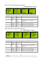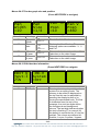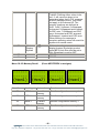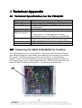
1
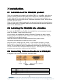
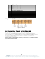
eyeheight
PM-2/2E
SDI on screen PPM unit.
user manual
Table of Contents
1 System Overview ........................................................................................... 4
1.1
Applications for the PM-2/2E................................................................ 5
1.2
Associated Equipment for the AD-2/AD-2E........................................... 5
1.2.1 Chassis Types.................................................................................. 5
1.2.2 Control Surfaces............................................................................... 5
2 Installation...................................................................................................... 7
2.1
Installation of the PM-2/2E product....................................................... 7
2.2
Installing the PM-2/2E into a flexiBox ................................................... 7
2.3
Connecting Video and audio to an PM-2/2E ......................................... 7
2.4
Connecting Panels to the PM-2/2E....................................................... 8
3 Operation ..................................................................................................... 10
3.1
Manual control of the PM-2/2E ........................................................... 10
3.2
Automation Control of the PM-2/2E .................................................... 10
3.3
Operational Menus for the PM-2/2E ................................................... 11
4 Technical Appendix ...................................................................................... 17
4.1
Technical Specification for the PM-2/2E ............................................. 17
4.2
Jumpering the I-BUS (CAN-BUS) Termination .................................... 17
-2eyeheightUnit 34 Park House Watford Business Park Greenhill Crescent Watford Herts GB WD18 8PH
Reg. No. 2855535 Telephone: +44 (0) 1923 256 000 Fax: +44 (0) 1923 256 100 email: [email protected]
Table of Figures
Figure 1-1 The PM-2E module........................................................................... 4
Figure 1-2 The PM-2 module. ............................................................................ 4
Figure 1-3 Typical PM-2/2E display.................................................................... 5
Figure 1-4 flexiBox with flexiPanel fitted ............................................................. 5
Figure 1-5 FP-10 desktop modular panel ........................................................... 6
Figure 1-6 1RU FlexiPanel................................................................................. 6
Figure 2-1 PM-2 I/O........................................................................................... 7
Figure 2-2 Pin Out of AES-IO Card 15 Way D-Type ........................................... 8
Figure 2-3 PM-2E I/O ........................................................................................ 8
Figure 2-4 I-Bus connection from chassis to panel.............................................. 9
Figure 4-1 Location Of I-Bus Termination Link.................................................. 17
-3eyeheightUnit 34 Park House Watford Business Park Greenhill Crescent Watford Herts GB WD18 8PH
Reg. No. 2855535 Telephone: +44 (0) 1923 256 000 Fax: +44 (0) 1923 256 100 email: [email protected]
1 System Overview
This manual describes the function of the PM-2/2E. The PM-2 unit is an AES
audio level display and the PM-2E provides audio level monitoring for embedded
audio.
The PM-2/2E will display program audio level information in-vision. The product
displays level information for two channels of audio. The PM-2 displays AES 1,
Channel 1 and 2. The PM-2E displays Group 1, Channel 1 & 2.
•
Configurable meter size and position.
•
Range of common audio scales.
•
Peak hold indicators.
Figure 1-1 The PM-2E module.
Figure 1-2 The PM-2 module.
-4eyeheightUnit 34 Park House Watford Business Park Greenhill Crescent Watford Herts GB WD18 8PH
Reg. No. 2855535 Telephone: +44 (0) 1923 256 000 Fax: +44 (0) 1923 256 100 email: [email protected]
1.1
Applications for the PM
PM--2/2E
Applications for the PM-2/2E include the following:
•
Studio operations including multi-screen use
•
Outside broadcast operations, saving the space of a conventional PPM unit.
Figure 1-3 Typical PM-2/2E display.
1.2
Associated Equipment for the ADAD -2/AD2/AD -2E
The PM-2/2E is a module and requires both a chassis and a control surface to
function.
1.2.1 Chassis Types
•
flexiBox is a 1RU chassis. The order code is FB-9. This will hold a
maximum of 6 PM-2/2E Modules with “Hot Swap” redundant PSU option
and “Hot Swap” PM-2/2E modules.
•
maxiBox is an alternative low cost 1RU chassis. The order code is MX-9.
This also will hold a maximum of 6 PM-2/2E modules but it has no
redundant PSU option and the PM-2/2E units must be factory fitted.
Figure 1-4 flexiBox with flexiPanel fitted
1.2.2 Control Surfaces
•
flexiPanel is a IRU control surface that fits on the Front of a 1RU flexiBox.
The order code is FP-9. A FlexiPanel can also be used in conjunction with
-5-
eyeheightUnit 34 Park House Watford Business Park Greenhill Crescent Watford Herts GB WD18 8PH
Reg. No. 2855535 Telephone: +44 (0) 1923 256 000 Fax: +44 (0) 1923 256 100 email: [email protected]
a maxiBox, in this case the extra accessory (Order code RR-9) will be
required
•
FP-10 is a desk mounting control surface (Order code FP-10). This unit is
a modular unit, which can be used in conjunction with the units below.
Figure 1-5 FP-10 desktop modular panel
Figure 1-6 1RU FlexiPanel.
-6eyeheightUnit 34 Park House Watford Business Park Greenhill Crescent Watford Herts GB WD18 8PH
Reg. No. 2855535 Telephone: +44 (0) 1923 256 000 Fax: +44 (0) 1923 256 100 email: [email protected]
2 Installation
Installation
2.1 Installation of the PMPM-2/2E product
If this unit is already pre-installed in a flexiBox (FB-9), or a maxiBox, with either a
local or a remote panel from the factory then refer to the "Hardware Installation
Guide" which will be enclosed with the system. If this unit is pre-installed in a
miniBox (MB-9), then also refer to the "Hardware Installation Guide" which will be
enclosed with the system
If this unit has been ordered separately, we assume here that you already have a
flexiBox system with a Flexipanel and that the flexiBox has at least one spare slot
above for the PM-2/2E card.
2.2 Installing the PM
PM--2/2E into a flexiBox
To install the PM-2/2E into a flexiBox it is desirable (but not necessary) to power
down the flexiBox. Follow these instructions.
On the rear of the flexiBox are 6 slots for Products. Remove any pair of spare
blanking plates one above another. There are 2 off M2.5 Screws, which require
unfastening for each blanking plate.
Slide the Product PCB into the spare slots and firmly push it home.
Use the two thumbscrews to fasten the unit in place.
Now refer to the "GeNETics User Guide". If your system consists of a single
flexiBox with a single flexiPanel then refer to the section titled "flexiPanel Auto
Set-up". If your system is part of a network with more than one flexiPanel then
refer to the section titled "flexiPanel Manual Set-up". This will guide you through
acquiring your product as a device on the flexiPanel.
2.3 Connecting Video and audio to an PMPM-2/2E
A diagram of the PM-2 I/O connector is shown below.
Figure 2-1 PM-2 I/O
Pin#
1.
2.
3.
Function
AES Input Channel 1 +ve
AES Input Channel 1 –ve
AES Input Channel 2 +ve
-7-
eyeheightUnit 34 Park House Watford Business Park Greenhill Crescent Watford Herts GB WD18 8PH
Reg. No. 2855535 Telephone: +44 (0) 1923 256 000 Fax: +44 (0) 1923 256 100 email: [email protected]
4.
5.
6.
7.
8.
9.
10.
11.
12.
13.
14.
15.
AES Input Channel 2 –ve
AES Output Channel 1 +ve
AES Output Channel 1 –ve
AES Output Channel 2 +ve
AES Output Channel 2 –ve
AES Output Channel 1 +ve
AES Output Channel 1 –ve
AES Output Channel 2 +ve
AES Output Channel 2 –ve
GPI Input 1 (not used)
GPI Input 2 (not used)
GND
Figure 2-2 Pin Out of AES-IO Card 15 Way D-Type
A diagram of the PM-2E I/O connector is shown below.
Figure 2-3 PM-2E I/O
2.4 Connecting Panels to the PMPM-2/2E
The PM-2/2E may be operated using a FP-9 or FP-10 flexiPanel locally or
remotely mounted. For detailed information on connecting remote panels, refer to
the section “Connection of Remote Panels to a flexiBox” in the geNETics
Hardware Installation Guide.
Below is shown a typical system consisting of an PM-2/2E in a flexiBox controlled
by a remotely mounted FP-9.
-8eyeheightUnit 34 Park House Watford Business Park Greenhill Crescent Watford Herts GB WD18 8PH
Reg. No. 2855535 Telephone: +44 (0) 1923 256 000 Fax: +44 (0) 1923 256 100 email: [email protected]
**
Connect Pins 1,2,4,7,9 from chassis to
panels (1:1). Use twisted pair AES
Digital Audio cable for pins 2 and 7. Pins
1,4,9 carry power 0.5 Amp, 13V. Use
cable with a least a 1 amp rating for pins
1,4,9. Cable llength should not exceed
250m.
**
I-Bus pins 2 & 7
** The I-BUS Network requires terminating with 100 Ohms at each extreme end of the network. Ensure that this is
done either by an external 100 ohm resistor OR ONE Panel/Product at each end has the termination set. See the
"Genetics User Guide" Under the sections "Flexipanel Power/I-BUS Jumpers".For the 4RU Panels see “4RU
Panel (FP-10) Jumpers for I-BUS” and “4RU Panel (VP-10, SW-10, AP-10) Jumpers for I-BUS” . Alternatively The
termination can be set on a Product (ie the AD-2/AD-2E module). Information about this is given in this manual.
Figure 2-4 I-Bus connection from chassis to panel
N.B. From 1/10/02 Eyeheight introduced a change in the flexiBox Chassis. Most
versions now have two 9 way connectors on the rear labelled “I-Bus” and “DBus”. The “I-Bus” connector is the same as the previously labelled “Can-B”
connector. Although a maxiBox is shown in this diagram the same arrangement
applies for a flexiBox chassis.
-9eyeheightUnit 34 Park House Watford Business Park Greenhill Crescent Watford Herts GB WD18 8PH
Reg. No. 2855535 Telephone: +44 (0) 1923 256 000 Fax: +44 (0) 1923 256 100 email: [email protected]
3 Operation
3.1 Manual control of the PMPM-2/2E
Manual Control of the PM-2/2E is done using one or more of the following control
surfaces:
•
The 1RU FP-9 Flexipanel.
•
The FP10 Desk mounting Panel
The FP-9 and the FP-10 have identical manual control systems. (The FP-10 is
simply a desktop version of the FP-9).
The PM-2/2E is, as are all genetics modules, controlled using a set of MENUS.
Each of these menus contains up to 3 parameters that are adjusted using the
rotary digipots. The Menus define all of the adjustable operational parameters in
the PM-2/2E. Pressing the rotary digipots brings the parameter to its default
value. Device selection is done using the device select switches which, when
pressed, will offer the name of the device in the LCD Window. Modules can be
acquired and then de-acquired using the set-up switch. For a full description of
the operation philosophy of the geNETics system, refer to the “geNETics User
Guide” (section “Operation of the flexiPanel”)
A full list of the Menus and their functions are given in section 3 of this chapter.
3.2 Automation Control of the PMPM -2/2E
Automation of the geNETics products is achieved via an RS422 port.** This port
is marked RS422 on the rear of a flexiBox. For the port to work a flexiPanel
MUST be connected locally on the front of the flexiBox.
Automation control of the PM-2/2E can be done using two protocol methods:
•
geNETics Automation Protocol.
•
PresTX Automation Protocol.
Genetics protocol is described in detail in the “GeNETics User Guide” section
titled “Automation Protocol on the geNETics Platform”. The menu list in section 3
of this chapter contains the data information for the protocol.
PresTX Automation Protocol is used only for the PresTX Presentation Mixer and
channel branding system. In this case an AU-2 Automation card is also required.
Refer to the PresTX Product manual
**On most flexiBoxes later than 1/10/02 the RS422 port has been replaced by a
“D-Bus” Port. The D-Bus port is for High Speed data transfer and is not used for
serial control. In order to achieve serial control of any products on an I-Bus
network Eyeheight Ltd have developed a RS232ÆI-bus converter “dongle”, (DG9) which enables greater flexibility of products on the I-Bus network whilst using
the same protocols as the RS422 port. Please refer to the “User guide for the
DG-9 eyeheight dongle and set-up software.
- 10 eyeheightUnit 34 Park House Watford Business Park Greenhill Crescent Watford Herts GB WD18 8PH
Reg. No. 2855535 Telephone: +44 (0) 1923 256 000 Fax: +44 (0) 1923 256 100 email: [email protected]
3.3 Operational Menus for the PM
PM--2/2E
Menus 00-03 Top Level Menus
Audio
Descrp
Menu Num.
00
01
02
03
AD-2/E
020903
Ver2.0
Heading
User
Name
Automation
Software
version
Monitoring
output
gain
NEXT
none
none
0ÆFF
0=0dB
FF=-77dB
none
Mon OP
Gain=
-0 dB
NEXT>
Function
This is the user-programmed name
for this unit. (see genetics user guide
for information as to how to program
names or aliases)
This displays the current software
version.
This adjusts the gain (volume) of the
Programme+AD mix AES monitoring
output.
Prompts the user to press the button
marked NEXT for further menu
options.
Menus 04-07, ident bar and audio alarm accept.
(Press NEXT/PREV to navigate)
Ident
Bar
=On
Menu Num.
4
5
6
7
Heading
Ident
Bar
Ident
Fader
Not used
Accept
alarm
Ident
Fader
=100%
Automation
Off,On
Default is On
0-100%
Default is 100%
Accept
alarm
Function
Pressing this will turn on or off the
Ident Bar.
The fade level of the Ident bar overlaid
on to the video image.
Pressing this accepts the current
alarm.
none
- 11 eyeheightUnit 34 Park House Watford Business Park Greenhill Crescent Watford Herts GB WD18 8PH
Reg. No. 2855535 Telephone: +44 (0) 1923 256 000 Fax: +44 (0) 1923 256 100 email: [email protected]
Menus 08-11 Screen display select.
(Press NEXT/PREV to navigate)
Audio
Bar
=On
Menu Num.
8
9
10
11
Fader
Bar
=On
Heading
Audio
Bar
Fader
Bar
Pan
Bar
Bar
Fader
Automation
0=Off
1=On
Default is On
0=Off
1=On
Default is On
0=Off
1=On
Default is On
0=0ff
296d=Full on
Pan
Bar
=On
Bar
Fader
=100%
Function
Pressing this will turn on or off the Audio
Bar.
Pressing this will turn on or off the Fader
Bar.
Pressing this will turn on or off the Pan
Bar.
The fade level of the Audio, Fader and
Pan bar overlaid on to the video image.
Menus 12-15 Ident bar size and position
(Press NEXT/PREV to navigate)
Text
H size
=1
Menu Num.
12
13
14
15
Text
V
size
0
Heading
Text
H size
Text
V size
Ident
H posn
Ident
V posn
Ident
H
posn
20
Automation
0-1,
Default is 1
Ident
V
posn
260
Function
This sets the horizontal size of the text.
0-1,
Default is 0
This sets the vertical size of the text.
0-999
Default is 20
This sets the horizontal position of the
Ident bar on the video image.
This sets the vertical position of the
Ident bar on the video image.
0-999
Default is 260
- 12 eyeheightUnit 34 Park House Watford Business Park Greenhill Crescent Watford Herts GB WD18 8PH
Reg. No. 2855535 Telephone: +44 (0) 1923 256 000 Fax: +44 (0) 1923 256 100 email: [email protected]
Menus 16-19 Audio bar graph size and position
(Press NEXT/PREV to navigate)
Audio
Width
=10
Menu Num.
16
17
18
19
Audio
Size
=Half
Audio
H
posn
10
Heading
Audio
Width
Audio
size
Automation
Audio
H posn
Audio
V posn
0-999
Default is 10
2-62
Default is 10
Audio
V
posn
10
Function
The width of the Audio bar.
The length of the Audio bar. The
following options are available ¼, ½
and Full.
This sets the horizontal position of the
Audio bar on the video image.
This sets the vertical position of the
Audio bar on the video image.
0=1/4
1=half
2=full
Default is half
0-999
Default is 10
Menus 20-23 Fader bar graph size and position
(Press NEXT/PREV to navigate)
Fader
Width
=10
Menu Num.
20
21
22
23
Fader
Size
=1/4
Fader
H posn
=10
Heading
Fader
Width
Fader
size
Automation
Fader
H posn
Fader
V posn
0-999
Default is 10
2-62
Default is 10
0=1/4
1=half
2=full
Default is 1/4
0-999
Default is 300
Fader
V posn
=300
Function
The width of the Fader bar.
The length of the Fader bar. The
following options are available ¼, ½
and Full.
This sets the horizontal position of the
Fader bar on the video image.
This sets the vertical position of the
Fader bar on the video image.
- 13 eyeheightUnit 34 Park House Watford Business Park Greenhill Crescent Watford Herts GB WD18 8PH
Reg. No. 2855535 Telephone: +44 (0) 1923 256 000 Fax: +44 (0) 1923 256 100 email: [email protected]
Menus 24-27 Pan bar graph size and position
(Press NEXT/PREV to navigate)
Pan
Width
=10
Menu Num.
24
25
26
27
Pan H
Posn
=10
Pan
Size
=1/4
Heading
Pan
Width
Pan
size
Automation
Pan
H posn
Pan
V posn
0-999
Default is 10
Pan V
Posn
=460
Function
The width of the Pan bar.
2-62
Default is 10
The length of the Pan bar. The
following options are available ¼, ½
and Full.
This sets the horizontal position of the
Fader bar on the video image.
This sets the vertical position of the
Fader bar on the video image.
0=1/4
1=half
2=full
Default is 1/4
0-999
Default is 460
Menus 28-31 Edit Ident bar information
(Press NEXT/PREV to navigate)
EDIT 0
Test-3
25N
Menu Num.
28
MD-9
System
=OFF
Heading
EDIT
Automation
none
Function
Pressing the return key switches the
system into an editing mode. The
memory to be edited is displayed on
the top line this can be adjusted by
pressing the display button or by
turning the associated knob. The first
6 characters form the text of the
message, the next two digits define
the foreground and background
colours. The last digit defines whether
the text is flashing (F) or normal (N),
the default is normal so the ‘N’ may be
omitted. The colours are defined as :
0=white, 1=cyan, 2=yellow, 3=green,
- 14 eyeheightUnit 34 Park House Watford Business Park Greenhill Crescent Watford Herts GB WD18 8PH
Reg. No. 2855535 Telephone: +44 (0) 1923 256 000 Fax: +44 (0) 1923 256 100 email: [email protected]
29
Master
Display
System
4=magenta, 5=blue, 6=red and
7=black. Defining either colour to be
red, 6, will cause an alarm to be
generated when that A.F.D. message
or error message occurs. This does
not apply to the channel ID. The
memory locations are defined as :
0=ID, 1=OK, 2=Absent, 3=Swapped,
4=Inverted, 5=Swapped and Inverted,
6=CRC error, 7=Swapped and CRC
error, 8=Inverted and CRC errorand
9=Swapped, Inverted and CRC error.
When editing of a message is
complete pressing return will revert the
system into normal mode.
If this system has a remote master
display system (Eyeheight product
code MD-9) then this must be set to
ON. Otherwise it must be OFF.
SPARE
SPARE
1=ON
2=OFF
30
31
Menu 32-35: Memory Recall
(Press NEXT/PREV to navigate)
------ ------ ------ ----------- ------ ------ -----(Mem1) (Mem2) (Mem3) (Mem4)
Menu Num.
32
Heading
MEM1
33
MEM 2
34
MEM 3
35
MEM 4
Automation
1 recalls
memory
1 recalls
memory
1 recalls
memory
1 recalls
memory
Function
Recalls configuration memory 1
Recalls configuration memory 2
Recalls configuration memory 3
Recalls configuration memory 3
- 15 eyeheightUnit 34 Park House Watford Business Park Greenhill Crescent Watford Herts GB WD18 8PH
Reg. No. 2855535 Telephone: +44 (0) 1923 256 000 Fax: +44 (0) 1923 256 100 email: [email protected]
Menu 36-39: Memory Save
Save
Mem.
#1
Menu Num.
36
37
38
39
(Press NEXT/PREV to navigate)
Save
Mem.
#2
Heading
SAVE
MEM1
SAVE
MEM2
SAVE
MEM3
SAVE
MEM4
Save
Mem.
#3
Automation
1 saves
configuration
1 saves
configuration
1 saves
configuration
1 saves
configuration
Menu 40-43: Power On Memory
41
42
43
Heading
Save
Power On
Memory
Recall
Power On
Memory
"Total
Reset ".
configuration as
configuration as
configuration as
configuration as
(Press PREV to navigate)
Set As Recall
Pow On Pow On
Memory Memory
Menu Num.
40
Function
Saves current
memory 1
Saves current
memory 2
Saves current
memory 3
Saves current
memory 4
Save
Mem.
#4
AD-2/E TOTAL!
020903 RESET!
Ver2.0 !!!!!!
Automation
1 to save
memory
Function
Saves current configuration as
Power On memory.
1 to recall
memory
Recalls the Power On memory
configuration.
1 to cause
Total Reset
This puts all current and power on
default settings to the factory
default
This displays the current software
version.
Software
version
- 16 eyeheightUnit 34 Park House Watford Business Park Greenhill Crescent Watford Herts GB WD18 8PH
Reg. No. 2855535 Telephone: +44 (0) 1923 256 000 Fax: +44 (0) 1923 256 100 email: [email protected]
4 Technical Appendix
4.1 Technical Specification for the PM
PM--2/2E
Number of Inputs
Type of Inputs
Line Length
Number of Outputs
1
270Mbit Serial Digital Video Inputs 75 Ohm
At least 200 Meters of PSF1/3 (Typically 275 Meters)
1 (PM-2), 3(PM-2E) Output BNC’s per Card
(Configurable).
Type Of Outputs
270Mbit Serial Digital Video Outputs, 75 Ohm, 800mV
Total Number Of
2, consisting of 1 Fixed Input and 1 Fixed Output (PMBNC Connections
2)
5, consisting of 1 Fixed Input and 3 Jumper
Configurable outputs. (One BNC not used)(PM-2E)
SDI Output Jitter
The system will add less than 0.2UI to the input Jitter.
(This is only guaranteed on issue 2 or later cards)
Current Consumption <800mA at +5V
Size
215mm by 100mm
4.2 Jumpering the I-BUS (CAN-BUS) Termination
The I-BUS Network is the "control system" under which all Products and Panels
are networked together. Under certain circumstances it is necessary to terminate
the network. This can be done on a Panel or a "Product". To terminate this
product, locate J6 on the PM-2/2E Processor Card supplied which is between U1
(The large square "chip") and the Edge connector. (This is on the half of the card
labelled "CHP-100 Spartan2 Processor"). Jumper this with a 2mm link.
J6
Figure 4-1 Location Of I-Bus Termination Link
- 17 eyeheightUnit 34 Park House Watford Business Park Greenhill Crescent Watford Herts GB WD18 8PH
Reg. No. 2855535 Telephone: +44 (0) 1923 256 000 Fax: +44 (0) 1923 256 100 email: [email protected]