1
EXTECH
INSTRUMENTS
PORTABLE
PRINTER
4500T THERMAL
4500THS Developers Manual
Rev. E
4500T_Developers_Manual(RevE).doc - 1/4/2008
2 of 57
4500T_Developers_Manual(RevE).doc - 1/4/2008
4500T Developers Manual - Table of Contents
1.0 Extech 4500T Printer Character Set ............................................................................................................... 6
1.1 Control Characters..................................................................................................................................................... 6
1.2 Printable Character Sets............................................................................................................................................ 7
1.2.1 ASCII and Extended International Character Set { 0x80..0xFF}..........................................................................................7
1.2.2 ASCII and Extended PC Line Draw Character Set{0x80..0xFF}.........................................................................................8
2.0 Extech 4500T Printer Font Control ................................................................................................................ 8
2.1 Printer Font Commands to select different character width.................................................................................. 8
2.2 Character Width Control Commands ...................................................................................................................... 9
2.3 Character Height Control Commands ..................................................................................................................... 9
2.4 Character Bold/Emphasized Print Control Commands ......................................................................................... 9
2.5 Line Spacing Commands ........................................................................................................................................... 9
2.6 Underline Command ................................................................................................................................................ 10
2.7 Reverse Printing Command..................................................................................................................................... 10
2.8 Printing direction...................................................................................................................................................... 10
The printing direction command allows the user to choose between right-to-left or left-to-right print text
directions. ........................................................................................................................................................................ 10
2.9 HT VT and FF Set Up Commands.......................................................................................................................... 11
2.10 Default Power Up Set UP ...................................................................................................................................... 11
2.11 Restore Defaults Command ................................................................................................................................... 12
3.0 8-Bit Dot Addressable Graphic Commands .................................................................................................. 13
3.1 8- Bit Dot addressable Graphic Commands........................................................................................................... 13
3.2 8-Bit Compressed Graphic Commands ................................................................................................................. 13
4.0 Bar Codes ....................................................................................................................................................... 15
4.1 Code 39 specifications............................................................................................................................................... 15
4.2 Code 128 specifications............................................................................................................................................. 15
4.2.1 UCC/EAN-128 specifications ................................................................................................................................................17
4.3 Interleaved 2 of 5 specifications............................................................................................................................... 17
4.4 UPC/EAN/JAN specifications.................................................................................................................................. 18
4.5 Codabar Specifications............................................................................................................................................. 18
5.0 Print Contrast Control ................................................................................................................................... 19
5.1 Auto Power Down Command .................................................................................................................................. 19
5.2 Extended Auto Power Down Command................................................................................................................. 20
5.3 Supervisory commands ............................................................................................................................................ 21
5.4 Printer Error Conditions ......................................................................................................................................... 21
5.5 Printer Operating Mode Commands ...................................................................................................................... 22
4500T_Developers_Manual(RevE).doc - 1/4/2008
3 of 57
5.6 End Of Text (EOT) Control Commands ................................................................................................................ 22
6.0 Label and Form Printing With Black Mark Option..................................................................................... 23
6.1 Black Mark Operation ............................................................................................................................................. 23
6.2 Black Mark Printer Commands.............................................................................................................................. 23
7.0 Page Printing Mode (Supported on firmware version 1.20 and later)......................................................... 24
7.1 Entering and Leaving Page Printing Mode............................................................................................................ 24
7.2 Page Printing Commands ........................................................................................................................................ 25
7.3 Form Fiesta ............................................................................................................................................................... 27
Appendix A ........................................................................................................................................................... 29
A.1.0 Introduction........................................................................................................................................................... 29
A.1.1 Flash Font Tables .................................................................................................................................................................29
A.1.2 Selection Font Tables............................................................................................................................................................30
A.1.3 Rotated Font Tables .............................................................................................................................................................31
A.1.4 Default Courier International and PC Line Graphic Font ...................................................................................................32
A.1.5 Monospace and Rotated Font Tables..................................................................................................................................33
A.1.6 Flash Font Downloading Commands ...................................................................................................................................34
A.1.7. Font Downloading – Example .............................................................................................................................................35
A.2.0 Graphic Logo Print Option................................................................................................................................. 37
A.2.1 Specification..........................................................................................................................................................................37
A.2.2 Generating Graphic Logos ...................................................................................................................................................38
A.2.3.Uploading Graphic Logos ....................................................................................................................................................40
Appendix B ........................................................................................................................................................... 41
B.1.0 Three Track magnetic Card Reader Option ...................................................................................................... 41
B.1.1 Card Specifications ...............................................................................................................................................................41
B.2.0 Magnetic Card Read command strings .............................................................................................................. 42
B.3.0 Magnetic Card Data Output Format .................................................................................................................. 42
B.4.0 Magnetic Card Read Error Messages ................................................................................................................. 43
B.5.0 Interfacing to the Magnetic Card Reader........................................................................................................... 43
Appendix C ........................................................................................................................................................... 44
Printer Configurations......................................................................................................................................... 44
C.1.0 Introduction........................................................................................................................................................... 44
C.2.0 Serial Communication Rate and Parity.............................................................................................................. 45
C.2.1 Serial Busy Protocol .............................................................................................................................................................45
C.2.2 XON/XOFF Protocol ...........................................................................................................................................................45
C.2.3 RS232C Connections ............................................................................................................................................................46
C.2.4 RS232C Technical Specifications .........................................................................................................................................46
C.3.0 Infrared Communications (IrDA) ...................................................................................................................... 47
C.3.0 Bluetooth Communications (Option) ................................................................................................................. 47
C.3.1 The Bluetooth™ interface power modification.....................................................................................................................48
C.3.2 MANUAL POWER OFF mode.............................................................................................................................................48
C.3.3 AUTOMATIC POWR OFF mode........................................................................................................................................48
C.4.0 802.11 Communication (Option) ......................................................................................................................... 49
C.5.0 Printer Status Indicator LED Panel................................................................................................................... 49
Appendix D........................................................................................................................................................... 50
4 of 57
4500T_Developers_Manual(RevE).doc - 1/4/2008
Bluetooth Setup Commands ................................................................................................................................ 50
4500THS QUICK REFERENCE........................................................................................................................ 54
4500T_Developers_Manual(RevE).doc - 1/4/2008
5 of 57
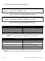
1.0 Extech 4500T Printer Character Set
Character Sets can be grouped into 3 categories – Control Characters, ACII Print Characters and Extended Print
Characters.
Control Characters
o Defined as character encoding {0x00..0x1F}
o Designed to control the printer operation
ASCII Print Characters
o Defined as character encoding {0x20..0x7F}
o Factory default – ISO defined US-ASCII alpha-numeric character set
Extended Print Characters
o Defined as character encoding {0x80..0xFF}
o Factory default – “International” and User Selectable “PC Line Draw” character set.
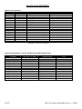
1.1 Control Characters
The following set of characters is reserved, for printer control. The printer also provides single byte responses to
inform the host of the printer status.
Character
Control
Hex / Dec
EOT
^D
0x04 / 04
HT
^I
0x09 / 09
LF
^J
0x0A / 10
VT
^K
0x0B / 11
FF
^L
0x0C / 12
^H
0x08 /08
CR
^M
0x0D / 13
SO
^N
0x0E / 14
SI
^O
0x0F / 15
XON
^Q
0x11 / 17
AUXON
^R
0x12 / 18
XOFF
^S
0x13 / 19
AUXOFF
^U
0x15 / 21
CANCEL
(OPTIONAL)
^X
0x18 / 24
ESC
^[
0x1B / 27
EXTEND
^\
0x1C / 28
EXTEND OFF
^]
0x1D / 29
BS
CONTROL ACTION
End Of Text
Printer sends an EOT character when buffer is empty; tells the host
device that printer is in idle mode.
Horizontal Tab
The horizontal TAB command advances the cursor by the number of
dots specified in the HT set up command.
Line Feed
Advance to beginning of next line.
Vertical Tab
Advance the cursor by the number of dot lines specified in the VT set
up command.
Form Feed
Advance the paper ( FEED) by the number of lines specified in the
Form Feed Set Up command.
Back Space
Back Space. Remove Previous character in Print Buffer.
Carriage Return
Advance to beginning of next line.
Shift Out
Every character following this command will be printed in double wide.
Shift In
Every character following this command will be printed in single width.
Transmitter On
Printer to Host: Ready to receive data.
Host to printer: The host is ready to receive data.
Printer on
Printer to Host: Printer is on line. Transmitted after initial power up or
clearing of printer jam or paper reload.
Printer receiver is off
Printer to Host: Print Buffer is full or other error condition.
Host to Printer: host device transmitter off.
Printer to Host: printer is off
Transmitted to host before power down or paper out.
Cancel and reset printer
Print buffer is cleared.
Escape
Escape character precedes graphics and printer operating modes.
Refer to escape command section.
Double High
All characters following this command are printed in double height.
Normal Height
The normal height command cancels the Double High command. All
character following this command will be printed single height.
Table 1.0 - Control Characters
6 of 57
4500T_Developers_Manual(RevE).doc - 1/4/2008
1.2 Printable Character Sets
The printer has two resident character sets – namely Courier International and Courier PC Line Draw.
Two commands are defined to select these character sets.
Command String
Esc – ‘F’ –‘ 1’
Esc – ‘F’ –‘ 2’
Selected Character Set
Courier International Character Set
Courier PC Line- Draw Character Set
Table 1.1 - Printable Character Sets
Note: Printer default Character Set is set to Courier International Character Set
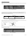
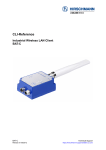
1.2.1 ASCII and Extended International Character Set { 0x80..0xFF}
ESC-‘F’-‘1’ command string selects the International character set. Printer defaults on this character set on
power up.
Figure 1.0 International Character Set
4500T_Developers_Manual(RevE).doc - 1/4/2008
7 of 57
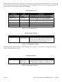
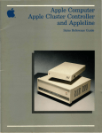
1.2.2 ASCII and Extended PC Line Draw Character Set{0x80..0xFF}
ESC-‘F’-‘2’ command string selects PC Line-draw character set.
Figure 1.2 – PC Line Draw Character Set
2.0 Extech 4500T Printer Font Control
Several commands are defined with the Extech 4500T printer which allows the user to select different
typefaces, change the character height, width as well as add emphasis or underline the printed text if desired.
The following sections explain in detail how to modify each of the features listed in this paragraph. For
complete details on Character sets as well as Font downloading please refer to Appendix A in this manual.
2.1 Printer Font Commands to select different character width
Listed below are the fonts installed and the three character command string to select them.
Monospace 821BT
20CPI Short Font
CHARAC
TER SIZE
(WxH)
10x18
Monospace 821BT
20CPI Bold
10x23
ESC+'k'+'8'
NO
80
Monospace 821BT
20CPI Normal
10x23
ESC+'k'+'7'
NO
80
Monospace 821BT
10 CPI Normal
20x23
ESC+'k'+'6'
NO
40
Courier Mode 5
24 CPI normal
8x23
ESC+'k'+'5'
YES
104
Courier Mode 4
21 CPI normal
9x23
ESC+'k'+'4'
YES
92
Courier Mode 3
19 CPI normal
10x23
ESC+'k'+'3'
YES
80
Courier Mode 2
16 CPI normal
12x23
ESC+'k'+'2'
YES
69
Courier Mode 1
12 CPI normal
16x23
ESC+'k'+'1'
YES
52
Courier Mode 0
13 CPI rotated
16x14
ESC+'k'+'0'
YES
52
FONT NAME
PITCH
DOWNL.
Num of
Chars /
Line
ESC+'k'+'9'
NO
80
SOFTWARE
COMMAND
Table 2.0 – Installed Fonts
8 of 57
4500T_Developers_Manual(RevE).doc - 1/4/2008
Note: Default printer settings are set to Courier Mode 3 - 19 CPI 80 columns per line.
2.2 Character Width Control Commands
A single byte control command is defined to control the printed character width.
Character
Control
Hex/Dec
SO
^N
0x0E / 14
Control Action
Shift Out
Each dot of the Character bit- Map is burned twice
Shift In
SI
^O
0x0F / 15
Each dot of the Character bit - Map is burned once
Table 2.1 - Character width control commands
Note: On power up the printer defaults to a single character width mode.
2.3 Character Height Control Commands
A single byte control command is defined to control the printed character height. Normal height of a character
is 23. EXTEND control character ( ^ \)selects a double height which is equal to 46 . EXTEND OFF control
character (^ ] )selects a normal height.
Character
Control Hex/Dec
EXTEND
^\
EXTEND OFF
^]
Control Action
Extended Print
0x1C/28
All characters following this command are printed double high.
Extended Print Off/Normal Print
0x1D/29
All characters following this command are printed normal height.
Table 2.2 – Height Control Commands
Note: Default printer settings are set to Normal Print.
2.4 Character Bold/Emphasized Print Control Commands
A line of text using a resident font may be emphasized with the three character commands from the table below.
Command String
Esc – ‘U’ – ‘1’
Esc – ‘U’ – ‘0’
Action Taken
Enable emphasized print starting with the current text line.
Disable emphasized print starting with the current text line.
Table 2.3 – Character Emphasis Print Control
Note: Default Printer Settings are set to Esc – U – 0
2.5 Line Spacing Commands
To set the line spacing between successive printed text lines and the number of line feeds desired at the
beginning of a line, use the three character commands from the table below. It is important to mention that
while printing PC Line-Draw characters, the line spacing must be set to zero, thus allowing graphic characters
on successive lines to be connected.
4500T_Developers_Manual(RevE).doc - 1/4/2008
9 of 57
Command String
Command Description
Esc – ‘a’ - n
Where n is the number of graphic-line-spacing, in increments of
0.125 mm. n = { 0..255}
Esc – ‘J’- n
Where n is the number of desired 0.125mm graphic line feeds n =
{0..255}.
Table 2.4 – Character Line Spacing
Note: Printer default setting is 3-dot line spacing after each printed text line. Please note that when a
character has the ‘’ around it, this means that it has to be typed exactly as shown. On the other hand
characters that don’t have the ‘’ around it like the “n” in the example above have to be entered while the Alt
key on the keyboard is being held. When using the above commands the height of the font in dot lines will be
subtracted from the total dot lines specified in the command.
2.6 Underline Command
The underline command allows the user to underline the desired portion of the text on a specific line or the
entire line if desired. Below are the command structure details.
Command String
Action Taken
All characters following this command will be underlined.
The underline command is terminated either by the Esc U n
command or by cycling the printer power.
All characters following this command will not be
underlined.
Esc – ‘U’ – ‘U’
Esc – ‘U’- ‘u’
Table 2.5 – Underline Command
Note: On power up the printer defaults to non underlined mode.
2.7 Reverse Printing Command
The reverse printing command enables the user to print in white letters on a black background. Below are the
command structure details.
Command String
Action Taken
Enable reverse printing starting with the characters following
the command. The reverse printing is terminated by the
Disable Reverse Command or by cycling the power.
Disable reverse printing starting with the characters
following the command. The disable reverse printing is
terminated by the Enable Reverse Command or by cycling
the power.
Esc – ‘U’ – ‘R’
Esc – ‘U’- ‘n’
Table 2.6 - Reverse Printing Command
Note: On power up the printer defaults to normal printing mode.
2.8 Printing direction
The printing direction command allows the user to choose between right-to-left or left-to-right print text
directions.
Command String
Esc-F-R
Esc-F-L
Printer Action
Right to left print
Left to right print
Table 2.7 – Printing Direction Command
10 of 57
4500T_Developers_Manual(RevE).doc - 1/4/2008
2.9 HT VT and FF Set Up Commands
The three command strings described in that section enable the user to set the HT, VT and FF values.
Command String
Action Taken
Sets up the FF value in dot lines (n2 * 256 + n1) where n1
and n2 = (0..255). Default value =2030
Sets the VT value in dot lines - n =(0..255) Default : n=203
Set the HT value in dot lines – n = (0..255) Default : n=100
Esc T F n1 n2
Esc T V n
Esc T H n
Table 2.8 – HT VT and FF Set Up commands
Note: When using the set up commands the height of the font in dot lines will be subtracted from the total dot
lines specified in the command. Thus for example if you are using a font which is 23 dot high and you send
Esc T V 200 (0xC8) the actual VT value will be 200 – 23 = 177 dots.
2.10 Default Power Up Set UP
A new feature in the 4500THS printer is that the user does not have to use the default set up of commands
anymore. Thus for example if the printer defaults to 83 columns on power up and you have an application
where you need the printer to default to 52 columns on power up you can easily achieve that by following the
instructions below. Please note that ANY of the supported printer attributes can be set using this method.
However please be careful to send meaningful commands only, otherwise you are risking of corrupting the
firmware.
The commands below must be sent sequentially:
==================================
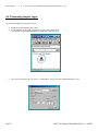
¾ Send <Esc> <’X’> <’X’>
¾ Send <Esc> <’D’> <’S’>
¾ Send <Esc> <’S’> <’L’>
¾ Send a binary file to initiate default start up
¾ Send <Esc> <’S’> <’T’> <0xFF> <CR><LF>
¾ Send <Esc> <’S’> <’B’> <CR><LF>
Note: The commands to change the default features have to be the first commands sent after power up.
Printer Command
<Esc> <’X’> <’X’>
Command Description
Enables flash
programming mode
<Esc> <’D’> <’S’>
Puts the printer into
downloading mode
<Esc> <’S’> <’L’>
Tells the printer that we
will be loading a file
next
Send File with Set Up commands
Send the binary file
which contains the
printer commands
<Esc> <’S’> <’T’> <0xFF> <CR><LF> Stop Loading
<Esc> <’S’> <’B’> <CR><LF>
Burn the file in Flash
Printer Response
None
<’?’>
None
None
None
<”D!X”>
Table 2.9 – Default Set Up Commands
4500T_Developers_Manual(RevE).doc - 1/4/2008
11 of 57
Example:
Esc X X
Esc D S
Esc S L
Esc k 1
Esc S T 0xFF <CR><LF>
Esc S B <CR><LF>
The example above will set the printer to default to 52 lines on power up.
2.11 Restore Defaults Command
The Restore Defaults command initializes all programmable attributes to factory default values. If custom
programming is present in flash memory, these will be restored as well, overriding the factory defaults.
Note: This command does not cancel the print buffer!
Command String
Action taken
Restores default values on printer
Esc–‘@’
Table 2.10 - Restore Default Command
User programmable printer attributes and their factory defaults are shown in the table below:
Attribute
Font
Character set
Underline
Bold
Reverse Printing (White on
Black)
Double Width
Double Height
Line spacing
Form Feed distance
Vertical Tab distance
Horizontal Tab distance
Printing direction
Contrast
Sensor Sensitivity
Auto Power Down time
Factory Default
Courier 3
International
Disabled
Disabled
Disabled
Disabled
Disabled
3 dots
2030 dots
203 dots
100 dots
Left-to-right
5
40
99 seconds
Table 2.11 - Programmable attributes and their default
12 of 57
4500T_Developers_Manual(RevE).doc - 1/4/2008
3.0 8-Bit Dot Addressable Graphic Commands
The Extech S4500THS printer uses a single line thermal head, which has 832 heating elements pitched at 0.125
mm. The total print width is 104 mm. The 8-bit graphic commands enable control of each one of the 832
heating elements and advancing of the paper by increments of 0.125 mm.
To select the 8-bit graphic mode the user application must issue the ESC-V command, next the host application
sends two bytes to indicate the number of the graphic lines desired, followed with a packet of 104 bytes for each
graphic line. The printer prints the graphic line and advances to the next line automatically.
3.1 8- Bit Dot addressable Graphic Commands
The following table displays the 8-bit dot addressable graphic commands and the printer actions. It also
illustrates the Commands with an example. Please note that characters <> ‘’ and ‘-‘ are not part of the
command string.
To achieve optimized smooth printing and to extend battery life when printing graphics, a Buffer Mode has
been implemented. In that mode the printer buffer accumulates an amount of data first and then prints the data
out. That is why when printing in graphics you may notice a slight pause before the printer starts printing. Pay
attention to the Power LED status – if steady that means data is being transferred across.
Command String
Esc-’V’-n1-n2
Esc-’J’-n
Esc-V-0x01-0x00
Printer Action
8-bit Graphic mode is selected. <n1> and <n2> is a 16 bit integer indicating the number of graphic lines of
104 characters each to be received. Valid Graphic character sets are from 0x00 to 0xFF Hex using bits 0-7.
Performs <n*0.125mm> feed.
’104 bytes of data’ This code prints a single line of graphic.
Table 3.0 – 8-bit Dot addressable Graphic Commands
3.2 8-Bit Compressed Graphic Commands
The 2 tables below describe the command used to print compressed graphics as well as explain in detail each of
the components of the command string.
Command String
Esc-’v’-height-width-counter-data-counter-data….
Printer Action
Prints a compressed graphic with the specified
attributes.
Table 3.1 – 8-bit Compressed Graphic Commands
4500T_Developers_Manual(RevE).doc - 1/4/2008
13 of 57
Graphic String
Component
Function of the component
An eight bit value representing the number of dot-lines contained in the following
data set
WIDTH
An eight bit value representing the number of bytes to be contained in each dot-line
(# of bytes in each line) of the following data set
An Eight bit value which describes how the following data will be processed
{127 ≥ Counter ≥ 0 } Process the next (Counter + 1 ) bytes of data as 8 bit graphics.
For Signed Values
{0 > Counter ≥ -128} Repeat the next single byte of data (( -Counter) + 1) times.
COUNTER
HEIGHT(# of lines)
{ 127 ≥ Counter ≥ 0} Process the next (Counter+1) bytes of data as 8 bit graphics
For Unsigned Values
{128 ≥ Counter ≤ 255} Repeat the next Singe byte of data, (( 256 – Counter)+1) times
Table 3.2 - Components of the compressed graphics command string
COMPRESSED GRAPHICS EXAMPLE:
The following graphics data is to be printed:
This data may be represented in hexadecimal:
0x55
0x55
0x55
0x00
0x00
0x55
0x00
0x55
0xAA
0x55
0x11
0x55
The RLE compressed graphics command:
ESC ‘v’ height width counterdata…
DEC 27 118 2
6
255
85
255 0
3
170 17 85 0
253 85
HEX 0x1B 0x76 0x02 0x06 0xFF 0x55 0xFF0x000x030xAA0x110x55 0x000xFD 0x55
14 of 57
4500T_Developers_Manual(RevE).doc - 1/4/2008
4.0 Bar Codes
The Extech 3750T printer supports several bar code symbologies. Two commands are defined for printing bar
codes.
Bar Code Command Formats
Esc- ‘z’-n1-n2-L-[data]
<CR><LF>
Esc- ‘Z’-n1-n2-L-[data]
<CR><LF>
Printer Action
Prints Bar code
only
Prints Bar code
and ASCII visible
n2
Command String Components
bar code type
‘1’ Code 39
‘2’ Code 128,UCC/EAN-128
‘3’ Interleaved 2 of 5
‘4’ UPC/EAN/JAN
‘5’ Codabar
number of character bytes in data array 1-255
L
Height of bar code printed in increments of 0.125mm
n1
Table 4.0 – Bar Code Command Formats
All barcodes are printed with the minimum bar width (“x-dimension”) of 0.250mm, in compliance with the
respective official specification.
4.1 Code 39 specifications
Description:
Each symbol starts with Leading Quiet Zone, followed with Start Symbol, Data Symbols,
ending with Stop Symbol and Trailing Quiet Zone.
Character set:
36 alphanumeric (0-9, A-Z) and '-' 'space' '$' '/' '+' '%'
Note: Only capital letters are supported.
Elements per symbol:
9 (5 bars, 4 spaces)
Character density: 6.25 CPI
Bar width:
0.25mm (narrow to wide ratio of 1:3).
Characters per line: 22 with auto center (maximum).
Command String
Esc-‘Z’-‘1’-0x07- 0x0a-‘CODE-39’
Printer Output
Prints CODE -39, 1mm high
Table 4.1 – CODE 39 Example
4.2 Code 128 specifications
Description:
Each symbol starts with Leading Quiet Zone, followed with Start Symbol, Data Symbols,
ending with Stop Symbol and Trailing Quiet Zone.
Character set:
Support for full 256 ASCII set among three subsets.
Elements per symbol:
6 (3 bars, 3 spaces)
Character density: 9.1 CPI
Bar width:
0.25mm
Characters per line: 32 alphanumeric characters, or 36 numeric only (maximum) - automatically centered.
4500T_Developers_Manual(RevE).doc - 1/4/2008
15 of 57
Code 128 Start character:
<start character> = {0x87, 0x88, 0x89} determines the character set to be printed
Start Character
0x020 through 0x03F ASCII
(#32 - #63)
0x040 through 0x07F ASCII
(#64 - #127)
0x020 through 0x07F ASCII
(#32 - #127)
Characters Read by Bar Code
Reader
0x020 through 0x03F ASCII
(#32 - #63)
0x00 through 0x07F ASCII
(#0 - #31)
0x020 through 0x07F ASCII
(#32 - #127)
PAIRS 0x030 through 0x039
ASCII
(#48 - #57)
PAIRS 0x030 through 0x039
ASCII
(#48 - #57)
Characters Sent to Printer
IF <start character> is 0x87 CODE
A
IF <start character> is 0x88 CODE
B
IF <start character> is 0x89 CODE
C
(Each number must be paired with
another)
Table 4.2 – Code 128 Start Character
Code 128 Data Bytes:
<DATA>
The data bytes are defined by which character set is defined. The printer accepts all characters 0x20h - 0x7Fh
with the translations defined above.
Also, characters 0x080 - 0x086 may be used as code 128 control characters:
HEX
DEC
CODE A
CODE B
CODE C
0x080
128
FNC 3
FNC 3
0x081
129
FNC 2
FNC 2
0x082
130
SHIFT
SHIFT
0x083
131
change to C
change to C
0x084
132
change to B
FNC 4
change to B
0x085
133
FNC 4
change to A
change to A
0x086
134
FNC 1
FNC 1
FNC 1
Table 4.3 – Code 128 Data Bytes
FNC 1: reserved CODE 128 character (used for UCC/EAN128)
FNC 2: message append (not supported by all bar code readers)
FNC 3: Initialize bar code reader
FNC 4: extend characters (bar code reader reads character + 128)
For example: 'a' is changed from #97 to #97+128 = #225
Notice: It is possible to switch code sets in the middle of the bar code. This is useful with heavily numeric
alphanumeric bar codes (see example below).
Code 128 EXAMPLES:
Print alphanumeric bar code "A2a", 12.5mm high, with human readable text:
n = 3 printed characters + 1 start character = 4
L = 12.5mm / 0.125mm = #100
start character = START B (full ASCII alpha numeric) = #136
16 of 57
4500T_Developers_Manual(RevE).doc - 1/4/2008
#27
0x1B
ESC
#90
0x5A
‘Z’
#50
0x32
‘2’
#04
0x04
0x04
#100
0x64
‘d’
#136
0x88
0x88
#65
0x41
‘A’
#50
0x32
‘2’
#97
0x60
‘a’
Print all-numeric bar code "1234", 5mm high, without human readable text:
n1 = 4 printed characters + 1 start character = 5
L = 5mm / 0.125mm = #40
start character = START C (numeric pairs) = #137
#27
0x1B
ESC
#122
0x7A
‘z’
#50
0x32
‘2’
#05
0x05
0x05
#40
0x28
‘(’
#137
0x89
0x89
#49
0x31
‘1’
#50
0x32
‘2’
#51
0x33
‘3’
#52
0x34
‘4’
4.2.1 UCC/EAN-128 specifications
Description:
The UCC/EAN-128 specification is an internationally recognized format for application
identifiers in code 128 bar codes. The bar code symbology is identical to Code 128.
These identifiers are not intended for point-of-sale applications. Only recognized bodies
of the UCC or EAN may assign application identifiers. More information may be found
at:
http://www.ean.be/ for the EAN and
http://www.uc-council.org/ for the UCC
EAN 128 EXAMPLES:
Print all-numeric bar code "1234", 5mm high, with human readable text in EAN-128 format:
n1 = 1 start character + EAN specified + 4 printed characters = 6
L = 5mm / 0.125mm = #40
start character = START C (numeric pairs) = #137
#27
0x1B
ESC
#90
0x5A
‘Z’
#50
0x32
‘2’
#06
0x06
0x06
#40
0x28
‘(’
#137
0x89
0x89
#134 #49
0x86 0x31
FNC1 ‘1’
#50
0x32
‘2’
#51
0x33
‘3’
#52
0x34
‘4’
4.3 Interleaved 2 of 5 specifications
Description:
Each symbol starts with Leading Quiet Zone, followed with Start Symbol, Data Symbols,
ending with Stop Symbol and Trailing Quiet Zone.
Character set:
numeric pairs.
Elements per symbol:
10 (5 bars, 5 spaces)
Character density: 11.11 CPI
Bar width:
0.25mm
Characters per line: 35 numeric (maximum), automatically centered.
Example:
Command String
Esc- ‘Z’-‘3’- 0x0A – 0x50 – ‘1234567890’
Printer Output
Prints interleaved 2 of 5 “
12345678” , 10 mm high
Table 4.4 – Interleaved 2 of 5 - Example
4500T_Developers_Manual(RevE).doc - 1/4/2008
17 of 57
4.4 UPC/EAN/JAN specifications
Description:
Each symbol starts with Leading Quiet Zone, followed with Left Guard Bars, Left Data
Symbols, Center Bar Pattern, Right Data Symbols, Check Character, ending with Right
Guard Bars and Trailing Quiet Zone.
The UPC, EAN/JAN-8, EAN/JAN-13 specifications comprise an internationally
recognized format for application identifiers. Unlike the UCC/EAN-128 specification,
these identifiers are intended for point-of-sale applications. Only recognized bodies of
the UCC and EAN may assign application identifiers. More information may be found
at:
http://www.ean.be/ for the EAN and
http://www.uc-council.org/ for the UCC
Character set:
numeric - fixed length.
Elements per symbol:
4 (2 bars, 2 spaces)
Character density: 14.5 CPI
Bar width:
0.25mm
Characters per line: UPC-A:
11 - plus check digit (automatically centered).
UPC-E:
6 - plus check digit (automatically centered).
EAN/JAN-8:
7 - plus check digit (automatically centered).
EAN/JAN-13:
12 - plus check digit (automatically centered).
Examples:
Command String
Esc – ‘Z’- ‘4’ – 0x0C-0xB8 - ‘123456789012’
Esc – ‘Z’-‘4’-0x07-0xB8 – ‘0783491’
Esc-‘Z’-‘4’-0x08-0xC8-‘65432109’
Esc-‘Z’-‘4’-0x0D-0xA0 – ‘6543216543219’
Printer Output
Prints UPC- A “123456789”, 23 mm high
Prints UPC-E “0783491”, 23 mm high
Prints EAN/JAN-8 “65432109”, 25 mm high
Prints EAN/JAN – 13 “6543216543219”, 20 mm high
Table 4.5 - UPC/EAN/JAN Examples
Note: in all the examples where ‘9’ is the last digit to be sent the received check digit ‘9’ is ignored and
recalculated in the printer. Also all heights are total height, including a 1.23mm drop bar pattern printed
after the bar code pattern.
4.5 Codabar Specifications
Description:
Each symbol starts with Leading Quiet Zone, followed with Start Symbol, Data Symbols,
ending with Stop Symbol and Trailing Quiet Zone.
Character set:
0-9, {$, -, :, /, ., +} and start/stop pairs {A/T, B/M, C/*, D/E}
Elements per symbol:
7 (4 bars, 3 spaces)
Character density: 8.1 CPI
Bar width:
0.25mm
Characters per line: 34 (maximum) plus start/stop, automatically centered.
Examples:
Command String
Esc-‘Z’- ‘5’-0x0A-0x78-‘A123456T’
Esc-‘Z’-‘5’-0x06-0x50-‘C2468*’
Printer Output
Prints Codabar “123456” , 15 mm high using the A start character
Prints Codabar “2468” , 10 mm high using the C start character
Table 4.6 – Codabar examples
18 of 57
4500T_Developers_Manual(RevE).doc - 1/4/2008
5.0 Print Contrast Control
The contrast of the printed text or graphics depends on the type of the thermal paper used, the printer
battery voltage and the printer contrast setting selected by the host application.
Ten levels of printer contrast settings are supported. This feature insures operation with different grades
of thermal paper available. The printer defaults to the middle contrast. The contrast may be changed by the host
application, using the <Esc-‘P’- n > command string.
During the printing process, the battery voltage and the thermal head temperature are monitored. The
print contrast is adjusted to assure consistent printout. The print speed is affected by the contrast setting; fastest
print speed is achieved if the contrast is set to 9.
Print Contrast Control Command String
Esc-‘P’-‘n’
Description of String Components
n= ASCII ‘0’ through ‘9’ { 0x30..0x39 }
‘0’ Highest contrast and lowest print speed
‘9’ Lowest contrast and highest print speed
Table 5.0 – Print Contrast Control Command
Note: Default setting is Esc-‘P’ – ‘5’
5.1 Auto Power Down Command
In order to conserve battery life the printer features an auto power down timer. If printer is in AUTO POWER
DOWN MODE (Dip Switch # 8 is ON) the power down timer defaults to 99 seconds on initial power up.
The auto power down timer may be set or disabled by sending recognized command strings. The auto power
down is re-started on every character received.
The auto power down timer may be disabled by activating the <RTS> input line, or setting the auto power down
timer to zero, the printer lowers the CTS output line and transmits Auxoff followed with Xoff before power
down. On power down the timer goes back to its default settings. See section 2.9 for saving settings
permanently in FLASH.
Command String
Printer Response
Esc-‘M’-‘n1’ – ‘n2’ – ‘0’-‘CR’
Sets the printer Auto power down timer (n1 and n2
may be ‘0’ to ‘9’)
Esc – ‘C’
Cancels MCR.
Table 5.1 - Auto power down commands
4500T_Developers_Manual(RevE).doc - 1/4/2008
19 of 57
Auto Power Down Command Examples:
Command String
Esc – ‘M’ – ‘0’- ‘0’- ‘0’ – ‘CR’
Esc – ‘M’- ‘9’ – ‘9’ – ‘0’ – ‘CR’
Printer Response
Disable the power out timer
Set the timer to 99 seconds
Table 5.2 – Auto Power Down Command Examples
5.2 Extended Auto Power Down Command
The Set Auto Power Down command allows the user to program the printer to automatically shut down after a
certain length of inactivity. This command accepts three formats: seconds, minutes and seconds, or hours,
minutes and seconds. When used in conjunction with the Default Power Up Setup command, this command will
allow for the power down timer value to be saved permanently in Flash.
Command String
Esc–‘M’–‘S1’ –‘S2’–‘0’–CR
Esc–‘M’–‘M1’–‘M2’–‘S1’ –‘S2’–‘0’–CR
Esc–‘M’–‘H1’–‘H2’–‘M1’–‘M2’–‘S1’ –‘S2’–‘0’–CR
Printer Response
Sets the printer Auto power
down timer to S1S2 seconds
Sets the printer Auto power
down timer to M1M2 minutes
S1S2 seconds
Sets the printer Auto power
down timer to H1H2 hours
M1M2 minutes S1S2 seconds
Table 5. 3 - Auto Power Down Command
Here, H1H2, M1M2 and S1S2 are two decimal characters that denote hours, minutes and seconds respectively.
Values range from ‘00’ to ‘99’ and values over 59 are carried over. Up to 18 hours may be specified, although
the battery will usually not last that long. The CR character at the end of the command is mandatory. The Print
Status Request command (^B) is useful for verifying that this command executed properly.
Command String
Hex
[Esc] M 5 4 0 [CR] 1B 4D 35 34
30 13
[Esc] M 7 6 5 4 0 [CR] 1B 4D 37 36 35
34 30 13
[Esc] M 9 8 7 6 5 4 0 [CR] 1B 4D 39 38 37
36 35 34 30 13
Action taken
Sets the Auto power down
timer to 54 seconds
Sets the Auto power down
timer to 1 hour 16 minutes
54 seconds
Sets the Auto power down
timer to 18 hours
Comment
76 minutes got
converted into 1 hour
16 minutes
98 hours got
truncated to 18 hours
Table 5.4 – Examples of the extended auto power down command
20 of 57
4500T_Developers_Manual(RevE).doc - 1/4/2008
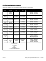
5.3 Supervisory commands
Single byte supervisory commands are designed to provide the user of the printer with the current
battery and print buffer status. The single byte supervisory commands and serial RS232 response strings are
summarized below.
Note: <4 ASCII hex digits> are read as hex nibbles ORed with 0x30.
Printer Command
Command String
Print Status Request
<CTRL B>
Battery and Print Head
Status Request
<CTRL V>
(Battery voltage reading valid
if adapter is not plugged in)
Firmware Version Query
<ESC><’P’><’(‘>
Hardware Model Query
<ESC><’P’><’)’>
Printer Response
<Esc><‘B’>
Print Buffer Status
<4 ASCII digits> <CR><LF>
<Esc><‘B’>
Print Buffer Status
<4 ASCII digits> <CR><LF>
<Esc><‘V’>
Battery Voltage Status
<4 ASCII digits> <CR><LF>
Print Head
<Esc><’T’>
Temperature
<4 ASCII digits><CR><LF>
<Esc> <’(‘>
Firmware Version
<4 ASCII characters><CR><LF>
<Esc ><’(‘>
Example v1.00
<’1’ ‘0’ ‘0’ ‘’ > <CR><LF>
Hardware model
<ESC><’)’>
<4 ASCII characters> <CR><LF>
Table 5.5 – Supervisory Commands
5.4 Printer Error Conditions
Below is a table which describes Different Error conditions and their corresponding LED status:
Error Condition
LED Status
Print Head is Hot
Power LED – Flashing Red
Status LED – Flashing Red
Printer is out of Paper/ Paper
Door is Open
Power LED – Green Blue or
Orange depending on
communication mode
Status LED – Steady RED
Error Condition Recovery
Printer stops printing at:
Print Head Temperature of 79º C
Printer Resumes Printing at:
Print Head Temperature of 75º C
Printer Stops printing when:
Out of paper or Paper Door is open
Printer Resumes Printing when:
Paper loaded or paper door is
closed AND FEED button is
pressed.
Battery Status LED- flashing RED
Battery Running Low
Battery Voltage 6.5V
Battery Extremely Low
Battery Voltage 6.3V
When Battery is running low while
printing is in progress.
Battery LED – Steady Red
Status LED - Flashing RED
Occurs only when printer is
initially powered ON and Battery is
very Low
4500T_Developers_Manual(RevE).doc - 1/4/2008
Finish printing current job and
Recharge Battery!!!
Turn Printer OFF and Recharge
Battery!!!
21 of 57
Table 5.6 – Printer Error Conditions
Note: To recover from “Out of paper Error” it is necessary to press the FEED button in addition to loading
the paper and/or closing the paper door. This is implemented in order to allow for the paper roll to adjust
itself before continuing with the printout so that no characters get “cut off” the receipt.
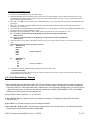
5.5 Printer Operating Mode Commands
The printer can be operated in two modes, Online or Buffer modes. In online mode, the characters are
printed as they are received. In buffer mode, the characters received are stored in the print buffer and printed
upon receipt of EOT character (^D). Also if the printer is in Buffer Mode and the print buffer is full, then the
printer will start printing but it will stay in the Buffer Mode until the Online Mode command is sent to the
printer.
Command String
Esc-‘P’-‘#’
Esc-‘P’-‘$’
Selected Mode
Selects Online Mode
Selects Buffer Mode
Table 5.7 – Printer Operating Mode Commands
5.6 End Of Text (EOT) Control Commands
End Of Text (EOT) control character is transmitted once when the printer buffer is empty. This control
character can be enabled or disabled via the commands given in table 5.8.
Command String
Esc-‘P’-‘+’
Esc-‘P’-‘-’
Selected Mode
Enable EOT control character transmit
Disable EOT control character transmit
Table 5.8 – End Of Text (EOT) Control Commands
22 of 57
4500T_Developers_Manual(RevE).doc - 1/4/2008
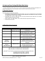
6.0 Label and Form Printing With Black Mark Option
The Extech S4500THS thermal printer can print on label and preprinted form stocks, with black mark located on the
right side of the paper stock. The printer paper out sensor is used to sense the black mark position.
6.1 Black Mark Operation
Follow these steps to use the black mark option.
• Set the paper out sensor sensitivity level by issuing <ESC> <‘Q’> <‘Q’> <n> command string. The value selected
for the sensitivity is dependant upon the height of the pre-printed black mark located on the label or form stock.
The default power on value of <n> is 40 (0x28).
• Issue <ESC> <‘Q’> <‘F’> <m> or <ESC> <‘Q’> <‘B’> <m> printer Command to find the black mark. The command
position’s the label or the form for printing.
• Wait for <ESC> <‘Q’> <0x3F> <0x3F> <n1> <n2> black mark found response from the printer.
• Send the data to be printed.
6.2 Black Mark Printer Commands
Black Mark Command
Reverse Dot Feed
<ESC> <‘Q’> <‘J’> <n>
Command String
Out of Paper Sensitivity
<ESC> <‘Q’> <‘Q’> <n>
Forward Black Mark Seek
<ESC> <‘Q’> <‘F’> <m>
Reverse Black Mark Seek
<ESC> <‘Q’> <‘B’> <m>
Printer Black Mark
Response:
<ESC> <‘Q’> <0x3F>
<0x3F> <n1> <n2>
Printer Black Mark
Response:
<ESC> <‘Q’> <0x30>
<0x30> <n1> <n2>
Paper Found
Paper Not Found
Description
Perform <n> reverse dot line feeds,
0.125mm each.
On paper detect fail, postpone the paper
out error response for <n> 0.125mm dot
lines before flagging a paper out error.
Seek black mark using forward feed until
<m> dot line feeds have been processed,
each dot line feed 0.250mm.
Seek black mark using backward feed until
<m> dot line feeds have been processed,
each dot line feed 0.250mm.
n1 and n2 are the high and the low nibble,
respectively, describing how many
(0.25mm) dot lines were required to find
black mark.
n1 and n2 are the high and the low nibble,
respectively, describing how many
(0.25mm) dot lines were processed before
reporting black mark status.
Notes:
<n> Total number of 0.125mm dot lines, 0x00 through 0xFF.
<m> Total number of 0.250mm dot lines, 0x00 through 0XFF.
n1 and n2 The total number of 0.125mm dot lines processed, while seeking the black mark.
n1 holds the high four bits (0x30 + 4 high bits).
n2 holds the low four bits (0x30 + 4 low bits).
n1 and n2 can have values 0x30 through 0x3f.
Table 6.0 – Black Mark Printer Commands
4500T_Developers_Manual(RevE).doc - 1/4/2008
23 of 57
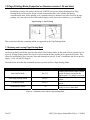
7.0 Page Printing Mode (Supported on firmware version 1.20 and later)
In addition to being a line printer, the Extech 4500THS can operate in Page Printing mode. Page
Printing Mode can be used to design a certain format and replace only variable data during
communication time. In line printing, text is printed from top to bottom in the order received. In page
printing, text, barcodes as well as lines and rectangles can be placed at an arbitrary (x, y) coordinate.
Page Printing vs. Line Printing
This section describes the commands which are supported by the Page Printing Mode.
7.1 Entering and Leaving Page Printing Mode
On Power up the Extech Printer goes into the default Line Printing Mode. In that mode all data is printed as it is
received. In Page Printing mode, the canvas is constructed in advance and the form is printed afterwards. This
allows for positioning of text, barcodes, lines and rectangles at specific X and Y coordinates and also at specific
angles – 0, 90, 180 and 270 degrees.
The table below describes the commands necessary to enter and leave Page Printing Mode:
Command Name
Command String
Enter Buffer Mode
Esc P $
Enter Page Printing Mode
Esc P P
Exit Buffer Mode
Esc P #
Print Buffer Content
^D
Command Description
Printer Enters Buffer Mode. In that
mode all data is retained in the
Buffer until ^ D ( 0x04) is received.
Places the printer in Page Printing
Mode
Places printer back in Line print
Mode
Prints Buffer Content and printer is
ready to receive more data.
Table 7.0 – Commands to enter and leave Page Printing Mode
24 of 57
4500T_Developers_Manual(RevE).doc - 1/4/2008
7.2 Page Printing Commands
Once the printer is placed in Page Printing Mode follow the commands from this section to draw objects on the
canvas.
Command
BeginPage
EndPage
SetMargin
SetPageSize
Parameters
();
();
(lm, tm);
(width, height);
Description
Enters page printing mode.
Exits page printing mode and prints a label.
Sets the left margin to lm and top margin to tm.
Defines the valid drawing area for a label.
Table 7.1 – Page Printing Commands
A page printing session begins with the BeginPage(); command and ends with the EndPage(); command. Rendering of a
page is done in memory. The user is given the option to define the drawing area with SetMargin(lm, tm); and
SetPageSize(width, height); commands. SetMargin(lm, tm); sets the left and top margins and SetPageSize(width, height);
sets the size of a page. All the measurements are in dots
Text Command
Command
DrawText
Parameters
(x,y,color,angle,"string");
Description
Draws text at coordinate (x, y). color
specifies text color. angle specifies text
direction. String is the text to print.
Table 7.2 – Drawtext Command
DrawText “data” prints the text enclosed in the double quotes at the current cursor location. x and y specify where the text
is printed. It is the upper left corner of the first letter of the top line, to be precise.
Color=1 prints black text. User may print white text on an existing black background by specifying color=0. Angle
specifies the text direction, as follows:
Angle
0
1
2
3
Print angle
0 degrees Counterclockwise
90 degrees Counterclockwise
180 degrees Counterclockwise
270 degrees Counterclockwise
Description
Prints text horizontally from left to right.
Prints text vertically in the up direction
Prints text horizontally from right to left
Prints text vertically in the down direction.
Table 7.3 – Angle Parameter
4500T_Developers_Manual(RevE).doc - 1/4/2008
25 of 57
Multiple lines can be printed with a single DrawText command by separating the lines with \n characters. Text formatting
is accomplished by tags inserted into the string argument. The formatting is effective only in the string that it appears and
does not carry over to the subsequent DrawText commands.
Text Formatting Codes
Command
<b>, </b>
<ul>, </ul>
<height = value>
Name
Bold
Underline
Text Height
<width = value>
Text Width
<font = value>
\n
\<, \>, \”, \\
Font
New Line
Literals
Description
Text enclosed by <b> and </b> appear in bold.
Text enclosed by <ul> and </ul> are underlined.
Text height is magnified by the given numeric
value. Use <height = 1> to return to original size.
Text width is magnified by the given numeric
value. Use <width = 1> to return to original size.
Sets the font. value = {9 .. 0}.
Moves the cursor to the beginning of the next line.
Use backslashes to print these special characters.
Table 7.3 – Text Formatting Codes
DrawRectangle Command
Command
DrawRectangle
Parameters
(x1, y1, x2,
y2,color,width);
Description
Draws a rectangle whose corners are (x1, y1) and
(x2, y2). color specifies the line or fill color. width
specifies the line width of a hollow rectangle. A
zero-width results in a filled rectangle.
Table 7.4 – DrawRectangle Command
DrawRectangle draws either a hollow or a filled rectangle. (x1, y1) and (x2, y2) specify the two diagonally opposing
corners. All measurements are in dots.
Barcode Command
Command
DrawBarcode
Parameters
(x, y, angle,
annotate, type,
height, “data”);
Description
Draws a 1-D barcode of the given angle, type,
width and data at coordinate (x, y). Setting annotate
to 1 causes human-readable text to appear below.
Table 7.5 –DrawBarCode Command
26 of 57
4500T_Developers_Manual(RevE).doc - 1/4/2008
DrawBarcode draws a 1-D barcode. (x, y) specify where the upper left corner of the barcode is placed. Supplying values
0, 1, 2, or 3 to the angle parameter causes the barcode to appear rotated 0, 90, 180, or 270 degrees.Setting annotate to 1
causes human-readable text to appear below the barcode. 0 disables this. The type parameter specifies the barcode type as
follows:
Type
Barcode
type
1
Code 39
2
Code 128
3
Code 2 of 5
4
UPC
5
Codabar
Table 7.6 – BarCode Ennumeration
The height parameter sets the height of barcode in units of dots. The “data” parameter specifies the content of the
barcode. It is the user’s responsibility to supply data that is appropriate for the chosen code. For example, Code 39 will
not accept lower case alphabets.
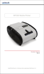
7.3 Form Fiesta
Form Fiesta is a Form and Label Generating Software which can be used to automate the process of label design. It is
provided to Extech partners and customers Free of charge. All supported commands from section 7.2 are implemented in
Form Fiesta and are automatically generated when an element is drawn onto the canvas on the screen.
Developers can use Form Fiesta to generate a Label. Then they can copy the commands generated in the yellow
section of the screen (these are the commands which render the image on the screen) in their application.
The variable data can be acquired by their application and replaced in the command string.
The code below demonstrates how to implement that in a simple VB program. CustomerName and csCarModel are
two
variables which get substituted in the string.
Private Sub Command1_Click()
csTicket = Chr$(27) + "P$" + Chr$(27) + "PP" + vbCrLf + "BeginPage();" + vbCrLf
csTicket = csTicket + "SetPageSize(400,200);" + vbCrLf
csTicket = csTicket + "DrawRectangle(30,0,330,40,1,0);" + vbCrLf
csTicket = csTicket + "DrawText(80,10,0,0,""<f=6><b>Dollar Rental"");" + vbCrLf
csTicket = csTicket + "DrawText(30,60,1,0,""Customer"");" + vbCrLf
csTicket = csTicket + "DrawRectangle(140,50,330,90,1,3);" + vbCrLf
csTicket = csTicket + "DrawText(150,60,1,0,""" + CustomerName + """);" + vbCrLf
csTicket = csTicket + "DrawText(30,110,1,0,""Model"");" + vbCrLf
csTicket = csTicket + "DrawRectangle(140,100,330,140,1,3);" + vbCrLf
If Option1.Item(0) Then csCarModel = "Taurus"
If Option1.Item(1) Then csCarModel = "Cavalier"
If Option1.Item(2) Then csCarModel = "Neon"
csTicket = csTicket + "DrawText(150,110,1,0,""" + csCarModel + """);" + vbCrLf
csTicket = csTicket + "EndPage()" +vbCrLf+Chr$(27)+"P#" + vbCr+Chr$(4)+vbCrLf
4500T_Developers_Manual(RevE).doc - 1/4/2008
27 of 57
Ticket.TicketText = csTicket
Ticket.Visible = True
MSComm1.CommPort = 1
MSComm1.PortOpen = True
MSComm1.Output = csTicket + vbCrLf
MSComm1.PortOpen = False
End Sub
Form Fiesta Install File as well as instructions on using the software are available on the Developer’s CD under the Page
Printing Folder.
28 of 57
4500T_Developers_Manual(RevE).doc - 1/4/2008
Appendix A
A.1.0 Introduction
The 4500THS features improved font and logo table organization which requires a new set of downloading
instructions. The paragraphs below describe in detail the 4500THS flash font and logo table organization as
well as the procedures for Font and Logo Downloading.
A.1.1 Flash Font Tables
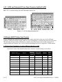
The table below shows the Font Table organization in the 4500THS printer. Please note the following:
1) The fonts in Red are permanent and can not be modified via the font downloading commands
2) Each font table represents either the first or the second half of a font, not the complete 255 character set.
For instance the location R1-C1 of memory, contains the International characters set of Courier Mode 1
- 16x23 (starting from 0x80 to 0xFF).
REPLACEABLE USER FONTS
R0
R2
Monospace
Monospace
Monospace
Monospace
10x23
10x23
10x18
Courier
Mode 0
Courier
Mode 1
Courier
Mode 2
Courier
Mode 3
Courier
Mode 4
Courier
Mode 5
16x14
16x23
12x23
10x23
9x23
8x23
C0
C1
C2
C3
C4
C5
ASCII
ASCII
ASCII
ASCII
ASCII
ASCII
ASCII
ASCII
ASCII
0x20..0x7F
0x20..0x7F
0x20..0x7F
0x20..0x7F
0x20..0x7F
0x20..0x7F
0x20..0x7F
0x20..0x7F
0x20..0x7F
0x80..0xFF
International
Set
0x80..0xFF
International
Set
0x80..0xFF
International
Set
0x80..0xFF
International
Set
0x80..0xFF
International
Set
0x80..0xFF
International
Set
0x80..0xFF
International
Set
0x80..0xFF
International
Set
0x80..0xFF
International
Set
0x80..0xFF
Rotated PC
Line Draw
PC Line
Draw
PC Line
Draw
PC Line
Draw
PC Line
Draw
PC Line
Draw
PC Line
Draw
PC Line
Draw
PC Line
Draw
PC Line
Draw
0x80..0xFF
0x80..0xFF
0x80..0xFF
0x80..0xFF
0x80..0xFF
0x80..0xFF
0x80..0xFF
0x80..0xFF
0x80..0xFF
0x80..0xFF
(Rotated)
I0x20..0x7F
R1
FACTORY FONTS
Rotated PC
Line Draw
20x23
Bold
C6
C7
C8
C9
Table A.0 – 4500THS Flash Font Table Organization
Note:
Use the following commands to select the memory location where the font will be uploaded (See
Section A.1.4 for a detailed description of the commands)
Esc-‘F’-‘K’- k - <CR>
Esc-‘F’-‘F’- f - <CR>
Where k is the value of the column (C)
Where f is the value of the row (R)
For instance the commands Esc-‘F’-‘F’- 1 - <CR> and ‘F’-‘K’- 2 - <CR>, indicates that the
new font will replace the current International-Courier Mode 2 set.
4500T_Developers_Manual(RevE).doc - 1/4/2008
29 of 57
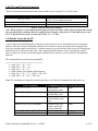
A.1.2 Selection Font Tables
Commands Esc-‘F’-‘f’- <CR> and Esc-‘k’-‘x’ - <CR> are used to select a font table
k0
F1
Courier
Mode 0
International
Set
16x14
Rotated
F2
Courier
Mode 0
Pc Line
Draw Set
16x14
Rotated
k1
k2
k3
k4
k5
k6
K7
k8
k9
Courier
Mode 1
Courier
Mode 2
Courier
Mode 3
Courier
Mode 4
Courier
Mode 5
Monospace
Monospace
Monospace
Monospace
20x23
10x23
10x23
10x18
16x23
12x23
10x23
9x23
8x23
Courier
Mode 1
Courier
Mode 2
Courier
Mode 3
Courier
Mode 4
Courier
Mode 5
16x23
12x23
10x23
9x23
8x23
Bold
Monospace
Monospace
Monospace
Monospace
20x23
10x23
10x23
10x18
Bold
Table A.1 – 4500 font sets
For instance commands Esc-‘F’-‘1’- <CR> and Esc-‘k’-‘3’, select the International Courier
Mode 3 (10wX23h)
30 of 57
4500T_Developers_Manual(RevE).doc - 1/4/2008
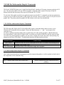
A.1.3 Rotated Font Tables
Rotated Font Table
Table A.2 - Default Rotated Font Tables
To select the PC Line Draw graphic table use the command
Esc-‘F’-‘1’ -<CR> or
Esc-‘F’-‘2’ -<CR>
Next select the Courier Mode 0 rotated font table using the command
Esc-‘k’-‘0’ : Select Rotated (16x14)
4500T_Developers_Manual(RevE).doc - 1/4/2008
31 of 57
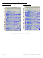
A.1.4 Default Courier International and PC Line Graphic Font
International Font Table
PC Line Graphic Table
Table A.1 - Default International and PC Line Graphic Font Tables
32 of 57
4500T_Developers_Manual(RevE).doc - 1/4/2008
A.1.5 Monospace and Rotated Font Tables
Monospace Font Table
Rotated Font Table
Table A.2 - Default Monospace and Rotated Font Tables
4500T_Developers_Manual(RevE).doc - 1/4/2008
33 of 57
A.1.6 Flash Font Downloading Commands
The table below summarizes all the font downloading commands supported by the 4500THS printer.
Command
String
Command
Description
Printer Response
m =1
Printer Response
m =0
LED Status
Esc-‘D’-‘F’
Enable font
downloading
?
?
Power LED – Steady Green
Status LED – Flashing Green
Esc-‘F’-‘I’
Display tables
Information
Display installed
Font tables info
(refer to Table 5)
‘1’: if command
correct ‘0’: otherwise
Esc-‘F’-‘S’<CR> or <LF>
Display font
download current
Settings
Esc-‘F’-‘S’ m t k f
Esc-‘F’-‘P’ – m t - k - f - <CR>
or <LF>
Set Font
Download
Parameter
Esc-‘F’-‘S’ m t k f
Esc-‘F’-‘M’- m <CR> or <LF>
To select Mode
Esc-‘F’-‘K’- k <CR> or <LF>
To select font
column(K) value
Esc-‘F’-‘S’-m t k f
‘1’: if command
correct ‘0’: otherwise
Power LED - Flashing green
Status LED - Steady RED
Esc-‘F’-‘F’- f <CR> or <LF>
To select font
row(F) value
Esc-‘F’-‘S’ m t k f
‘1’: if command
correct ‘0’: otherwise
Power LED - Flashing green
Status LED - Steady RED
Esc-‘F’-‘L’ – t <CR> or <LF>
Select file type
**and start of
font download
Send the .bdf
file
Esc-‘F’- ‘B’
<CR> or <LF>
Esc-‘F’-‘S’ m t k f
Esc-‘F’-‘S’ m t k f
‘1’: if command
correct ‘0’: otherwise
‘1’: if command
correct ‘0’: otherwise
‘1’: if command
correct ‘0’: otherwise
‘1’: if command
correct ‘0’: otherwise
On burn process
Complete:
D!X
Power LED – Steady Green
Status LED – Flashing Green
Power LED – Steady Green
Status LED – Flashing Green
Power LED – Steady Green
Status LED – Flashing Green
Power LED - Flashing green
Status LED - Steady RED
While File is transferring:
Power LED - Steady Green
Status LED - Steady RED
When transfer is complete:
Power LED - Flashing Green
Status LED - Shuts OFF
While the font is being burned in FLASH
Power LED – Steady Green
Status LED - Steady Red
When Burning complete
Power LED – Flashing Green
Status LED – Flashing Red
Send the File
To program or
burn font on
flash
Power LED – Steady Green
Status LED – Flashing Green
On burn process
Complete:
D!X
m: Down load operating mode:
m =0,standard response
m =1, response with diagnostic message (default)
k: column value
k = ‘0’ through ‘9’
f: row
f = ‘0’ through ‘9’
t: Font File type..
t = ‘0’ BDF formatted font file (default)
t= ‘1’ through ‘9’ reserved
Table A.3 – Font Download Commands
34 of 57
4500T_Developers_Manual(RevE).doc - 1/4/2008
Important Font Downloading Notes:
¾
¾
¾
¾
¾
¾
¾
The file to be downloaded has to be in a .BDF format.
When downloading make sure that the metrics of the fonts to be downloaded are equal or smaller than the metrics of the
existing font in the certain location. Otherwise the fonts will not be downloaded correctly. For specific Font metrics please
refer to the Font Table in section 2.1.
Esc – ‘D’ – ‘F’ <CR> has to be the first Esc Command after Power Up or else the printer will print the command instead of
executing it
Esc – ‘X’ - ‘X’ <CR> command simulates that state and can be used to bring the printer in initial state after other Esc
commands have been used.
After a font has been downloaded press the FEED button twice to get the printer out of the downloading mode and then shut
the printer OFF by pressing the ON/OFF switch.
The header on top of each character in the .bdf font has to represent the true size of the font bit – map.
Ex : for a 16x23 font the header at the beginning of each character needs to look like that:
BBX 16 23 0 0
Ex: for a 10 x 23 font the header at the beginning of each character needs to look like that:
BBX 10 23 0 0
If the font which you are going to download is one byte in size ( 8x 23) then in the .bdf file you will need to have one byte
only.
Otherwise the firmware will not accept the font!!!!!!!!
Ex:
BBX 08 23 0 0
BITMAP
0008
000F
THIS IS WRONG
0002
0003
Ex:
¾
BBX 08 23 0 0
BITMAP
08
0F
THIS IS CORRECT
02
03
The name of the font is indicated at the beginning of the .bdf file in the lines:
FONT Font12C.BDF
If you change the file name only the Firmware will not recognize the new name. You will need to open the .bdf file and
change the name in the above line.
A.1.7. Font Downloading – Example
1) Have the .BDF font file available and ready. The file should contain all of the characters which you want to download.
When downloading make sure that the Serial Port on your Terminal Program is configured for Hardware Handshaking.
If the file you have is in .asm format rather than a .bdf format you can use Extech’s asm2bdf utility to convert the file into
a .bdf format. Instructions on how to use the utility are available in the USING THE ASM2BDF UTILITY DOCUMENT
available in the FONT section on the Developer’s CD.
2) Cycle Printer Power or Send Esc- ‘X’ -‘X’ command
3) Send Esc D F Wait for a question mark to come back from the printer. The Ready and status LED should both
light up in green
4) Send Esc F I if you wish to see the current font tables Information
5) Send Esc F K 1 <CR> or <LF> – this will select the second column from the table above – the Power LED will start
flashing Green and the Status LED will turn steady RED.
4500T_Developers_Manual(RevE).doc - 1/4/2008
35 of 57
6) Send Esc F F 1 <CR>or <LF> – this will select the second row from the table above - the Power LED will start flashing
Green and the Status LED will turn steady RED.
7) Send Esc F L 0 <CR>or <LF> which will signal that the file you are sending is of .bdf format ( this command is
implemented primarily for future releases when users will be able to download more than one font format.) - the Power
LED will start flashing Green and the Status LED will turn steady RED.
8) Send the .bdf file - While the File is transferring the Power LED is steady Green and the Status LED is steady RED –
when the transfer is complete the Status LED shuts OFF and the Power LED is Flashing Green. The metrics of the
.bdf font have to be equal or smaller than the metrics of the existing font.
9) Send Esc F B <CR>or <LF> - The Power(green) and Status(red) LEDs are steady while the font is being burned in
FLASH and when completed both the Power LED (green) and the Status LED (red) start flashing.
10) The .bdf font which you just downloaded has been stored in the International Section of the Courier Mode 1 font.
Unplug the Serial Cable, Press the Feed button and then shut the printer by pressing the ON/OFF button.
36 of 57
4500T_Developers_Manual(RevE).doc - 1/4/2008
A.2.0 Graphic Logo Print Option
The following paragraphs summarize the operation of the Graphic Logo feature for the Extech S4500THS
printer. The Graphic Logo feature enables the storage of formatted Bitmap file in nonvolatile memory. Up to
eight memory sectors of up to 64,000 bytes each, are reserved to store Graphic Logo in the printer. Upon receipt
of a Graphic Logo print command, the Graphic Logo data is sent to the printer. The feature enables printing of a
stored graphic image as part of a receipt.
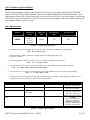
A.2.1 Specification
Printer
4500HS
Number of
Logos
8 (FLASH)
n =(0..7)
4-7 are
optional
Bytes per
logo
Dot lines per
logo
Dots per line
64,000
178
832
Table A.4 – Graphic Logo Specification
3)
On initial power-up, the Host application selects the Flash Logo Mode by sending the command String:
<ESC - D – L-<CR> or <LF>
Printer responds by sending ? character to the host application indicating that the Flash
Logo Mode is enabled.
4) The Host application selects the Graphic Logo record mode by sending the load command:
<ESC – L – G – n-<CR> or <LF>
5) Once the printer is placed in record mode, the Graphic Logo is downloaded using 8-bit graphic command:
<ESC> <V> <0x01> <0x00> <104 bytes of Graphic data>
6) The Graphic Logo record mode is terminated upon receiving the Graphic Logo record terminate command string.
ESC – L – G - 0xff -<CR> or <LF>
7) Printer saves the received Logo data in flash and sends D!X characters to the host, indicating that logo data was saved.
The printer power must be cycled to return to normal operating mode.
Command
Command Description
Printer Response
LED Status
Power LED - Steady Green
Status LED - Flashing Green
Power LED - Steady green
Status LED - Steady RED
Esc – D-L-<CR>or <LF>
Select Flash Logo Mode
?
Esc – L-G-n-<CR>or <LF>
Load/Record Graphic Logo
none
Send Graphic Logo File
Send a Binary file with the
Logo image
none
Esc- L-G-<0xFF>-<CR>or
<LF>
Stop Loading Graphic Logo
D!X
While the logo is being burned
in FLASH
Power LED – Steady Green
Status LED - Steady Red
When Burning complete
Power LED – Flashing Green
Status LED – Flashing Red
Esc-L-g-n
Print Graphic Logo
Printer Prints Logo n
none
Power LED - Steady Green
Status LED - Steady RED
Table A.5 – Graphic Logo Commands
4500T_Developers_Manual(RevE).doc - 1/4/2008
37 of 57
The characters ‘-‘ , ‘<’ or ‘>’ are not part of the command string. Decimal code for Esc is (27).
A.2.2 Generating Graphic Logos
To generate the graphic logo follow these steps:
8) Install the Extech 4500THS printer driver
9) Use WordPad or any Windows application to prepare your logo document
From printer Setup of WordPad application Set the paper margins to 0.16”.
•
Print your logo document to a file, name it <LOGO.PRN>, using The Extech 4500THS Windows driver.
38 of 57
4500T_Developers_Manual(RevE).doc - 1/4/2008
•
Go to DOS Window and start the EDIT program.
Go to Start and then select RUN and in the RUN window type EDIT and press ENTER. The program will open.
• Open <LOGO.PRN> file in BINARY mode.
Press <Ctrl> <Home> to place cursor at the beginning of file.
Delete everything in the beginning of the file up to but not including the arrow and the capital letter V next to it.
Move cursor to the end of the file, by pressing control End on your keyboard, There you will see 2 characters - a character which
resembles a circle with a cross attached to it (the FF character) and the line feed character. Delete these two characters.
•
Save the modified <logo.prn> file.
4500T_Developers_Manual(RevE).doc - 1/4/2008
39 of 57
A.2.3.Uploading Graphic Logos
To copy the Logo file to the printer follow these steps:
•
Use a serial communication program like Telix, Procomm or Windows HyperTerminal or Tera Term.
•
Check that the application is set to the same baud rate and parity as the printer.
•
Upload the LOGO.PRN file to the printer using a BINARY file transfer protocol. Follow these steps to
upload a logo file.
1)
2)
3)
4)
Cycle the power of the printer or Send Esc X X
Type Esc D L <CR> or <LF>. Status LED will start Flashing Green
Wait until a question mark comes back from the printer
Type Esc L G n <CR> or <LF> ( This shows the location where you want to download the logo
0..7). Status LED will turn Red
5) Send the logo file which you have just created
6) Send Esc L G 0xFF <CR> or <LF>
7) Wait for D!X response to come back from the printer. This indicates that file transmission and storage
is completed. Status LED will be flashing Red and the Power LED will be flashing Green
8) After a logo has been downloaded , unplug the Serial Cable , Press the FEED button to
get the printer out of the downloading mode and then shut the printer OFF by pressing the ON/OFF
switch.
9) To test the LOGO.prn file issue print commands : Esc L g n where n is the logo
location that you want to print
40 of 57
4500T_Developers_Manual(RevE).doc - 1/4/2008
Appendix B
B.1.0 Three Track magnetic Card Reader Option
A three track Magnetic Card Reader is available on the Extech 4500THS model printers. The MC reader is
designed to read magnetically encoded data from cards conforming to ANSI/ISO 7810, 7811 standards.
The MC reader converts the F2F encoded signals on the magnetic card, to ISO7811 compatible ASCII format
and transmit the information to the host computer or a terminal.
The MC reader can read one, two or three tracks simultaneously and bi-directionally.
Set of printer ESC software commands are supported in order to provide the following operating features:
y
y
y
y
Select the MC reader.
Set the auto time-out software timer
Report MCR Read errors
Report MC reader status.
B.1.1 Card Specifications
The table below summarizes the format of the data stored on each magnetic track.
Track Position
Recording
Density
Track 1
ISO1 (IATA)
210 BPI
Track2
ISO2 (ABA)
75 BPI
4500T_Developers_Manual(RevE).doc - 1/4/2008
Track3
ISO3(MINTS)
210 BPI
41 of 57
Recording
Capacity
Number of data
bits
Card
Thickness
79 characters
40 characters
7
107 characters
5
7
.76 mm +/- 0.08 mm
Table B.0 – Card Specifications
B.2.0 Magnetic Card Read command strings
Six Commands strings are provided, to read the magnetic cards. These commands are summarized in the tables
below. The general syntax for commands are as follows:
Command String – General Syntax
Command String - Example
<ESC><’M’><n>< n> Track #CR
<ESC><’M’> ‘9’ ‘ 9’
1 CR
Table B.1 – Magnetic Card Read Command Strings – general form
The ESC-M command turns on the power to the MC Reader
The next two bytes, <nn> are used to set the MC reader’s timer. "01" through "99" are valid timer settings
and “00” disables the timer.
The printer aborts and transmits the time-out error message, if the operator fails to swipe a card within the
time period set by the host application.
On timeout printer aborts the swipe process, transmits timeout error message and turns off the <READING>
LED.
A good magnetic card swipe automatically terminates the read process.
Magnetic Card Command String
ESC
ESC
ESC
ESC
ESC
ESC
ESC
–
–
–
–
–
–
–
M
M
M
M
M
M
C
-
nn
nn
nn
nn
nn
nn
-
1
2
3
4
5
6
–
–
–
–
–
–
Description
CR (CR = Enter)
CR
CR
CR
CR
CR
Read Track1 only
Read Track2 only
Read Track3 only
Read Track1 and Track2 simultaneously
Read Track2 and Track3 simultaneously
Read Tracks 1,2 and 3 simultaneously
Cancel MC Read process
nn = ASCII "01" through "99" seconds
nn = “00” disables the MC reader timer
Table B.2 – Magnetic Card Read Command Strings - Details
B.3.0 Magnetic Card Data Output Format
The track data retrieved from a magnetic card is transmitted to the host in ISO7811 ASCII format as
summarized in the table below.
The first four characters (“%/1/”) flag the track number, the track data follows the flag string, terminated
42 of 57
4500T_Developers_Manual(RevE).doc - 1/4/2008
with ‘?’-CR-LF.
‘%;+’ are the track start sentinel characters, While ‘?’ is the end of track sentinel character.
If no data is available for a track that data field will be empty. If an Error is encountered on any track a
single ‘E’ will be the output for that tracks data field.
Track1
%/1/
Data
Track 2
?CRLF
;/2/
Data
Track 3
?CRLF
+/3/
Data
?CRLF
Table B.3 - ISO 7811 ASCII Format
B.4.0 Magnetic Card Read Error Messages
The characters <%> and <E> preface all error messages. Following these two characters is a comma, the
error number in ASCII (01 through 99), another comma, English description of the error encountered and
finally CR-LF terminating the <Error Message> string. The syntax is as follows:
Error Message ( General Form)
<%><E>, nn , Error text in ASCII, <CR> <LF>
Table B.4 – Error Message – General Form
y
Where nn is error number encountered.
The printer may transmit Four (3) types of Read Error messages. The following messages terminated with
CR-LF are returned by the firmware:
Error #
05
07
09
Error Message Transmitted
Time-out Expired
Invalid Track Number
Cancel Request
Table B.5 – Error Message – Specific Examples
B.5.0 Interfacing to the Magnetic Card Reader
This section details the software steps required to access the MC reader from a computer or a
terminal.
The Host Selects the printer by activating the RTS input line or sending wake-up characters to the
printer.
4500T_Developers_Manual(RevE).doc - 1/4/2008
43 of 57
The Printer Sends the XON command to the host to indicate that it is ready to receive data from
host.
Once XON is received the host sends ASCII serial command string to enable the magnetic card
reader (e.g. Esc-m004-cr). The printer turns on the GREEN <READY> LED.
Once the operator swipes the magnetic card, the printer transmits in ASCII format the tracks
information found on the magnetic card.
A good read automatically turns off the MC reader and the <READY> LED.
The <READY> LED illuminates RED if an error is encountered, while reading the magnetic card.
Printer transmits timeout error message if the operator fails to swipe a card in the time period set by the host
application.
Appendix C
Printer Configurations
C.1.0 Introduction
The 4500THS printers support Serial RS232 and IrDA compatible infrared communication interfaces. Blue
Tooth and 802.11 communication is also available as an optional feature. Serial, IrDA, 802.11 and
Bluetooth communication settings can be changed via a DIP switch located on the control card. In the
following Sections Each Setting is discussed in more detail.
4500THS DIP SWITCH SETTINGS
Dip Switch
1& 2
3&4&5
44 of 57
Switch #
Switch
#
SW 1
SW 2
OFF
OFF
IrDA
ON
OFF
Bluetooth
OFF
ON
802.11b
ON
ON
Baud Rate
115200
57600
SW 3
OFF
ON
SW 4
OFF
OFF
Function
Communication
Interface
RS232
Switch
#
Notes;
Baud Rate can be negotiated up
to the value specified through
Dip switches 3,4 and 5
BT Baud Rate set for 115 200 bps
802.11 Baud Rate set for 115200
bps
SW 5
OFF
OFF
4500T_Developers_Manual(RevE).doc - 1/4/2008
6
7
8
38400
19200
14400
9600
2400
1200
OFF
ON
OFF
ON
OFF
ON
Parity Bit
Parity Enabled
Parity Disabled
Odd/Even
Even Parity
Checker
Odd Parity
Checker
Auto Power Save
SW 6
ON
OFF
SW 7
Does not apply for IrDA
Does not apply for IrDA
ON
Does not apply for IrDA
OFF
Does not apply for IrDA
SW 8
OFF
ON
Manual On/Off
Auto Power Down
Power Save Disabled
Power Save Enabled
ON
ON
OFF
OFF
ON
ON
OFF
OFF
ON
ON
ON
ON
Use for fixed IrDA
Table C.0 – 4500THS Dip Switch Settings
C.2.0 Serial Communication Rate and Parity
The RS232C Interface signals for the 4500THS Series printers are terminated on a 6 PIN RJ type data connector
located on the side of the printer. Six connections are provided from the Serial Interface to the host computer. A
minimum two connections are required for operation, RXD – pin 3 and Common – pin 1.The proper baud rate
and protocol settings are required to communicate with the host device. The printer defaults to 115200 BAUD, 8
DATA BITS, NO PARITY BIT, and two STOP BITs on initial power up. Two communication handshaking
protocols are supported by the 4500THS, Serial Busy protocol and XON/XOFF protocols.
C.2.1 Serial Busy Protocol
For the serial busy handshaking mode, request to send printer input (RTS) and clear to send printer output
(CTS) are used to control data flow to and from the printer.
The RTS and CTS are considered to be valid or active when the signal level is positive (3 to 12VDC). A
positive RTS signal from the host device enables the printer. The RTS signal is monitored during data
transmission from the printer to the host device, the printer transmits data to the host device only if RTS input is
high. The printer raises CTS output when it is ready to accept data. The printer lowers CTS line when the print
buffer has less than 256 unused locations.
C.2.2 XON/XOFF Protocol
For the XON/XOFF handshaking mode, the printer transmits XON (0x11) when it is ready to accept data, and
XOFF (0x13) for the print buffer has less than 256 unused locations. Under XON/XOFF protocol, the data flow
out of the printer's serial port is halted on receipt of XOFF from Host device and resumed on receipt of XON.
4500T_Developers_Manual(RevE).doc - 1/4/2008
45 of 57
C.2.3 RS232C Connections
The RS232C Interface signals for the Extech 4500THS are terminated on a 6 PIN RJ25 type data connector
located at the back of the printer.
Six connections are provided from the Serial Interface to the host computer. The table below lists the Serial
Interface signals and pin-outs on the RJ25 connector while pin locations are shown in Figure 2.
A minimum of two signal connections are required for operation, RXD - pin3 and Common - pin1.
RJ25 CONNECTOR PIN #
3
FUNCTIONAL DESCRIPTION
RS232 from Host
(INPUT)
RS232 from Printer
(OUTPUT)
Request to send from Host (INPUT)
Clear to send from Printer
(OUTPUT)
Logic common
2
6
4
1
5
SIGNAL NAME
RXD
TXD
RTS
CTS
COM
Table C.1 – Serial Interfaces Signals and pin-outs
C.2.4 RS232C Technical Specifications
Technical Specification Name
Data Transfer Rate
Word Length
Start Bit
Data Bits
Parity Bit
Stop Bits
Signal Levels
Mark or Logical 1
Space or Logical 0
Handshaking
Hardware
Software
Auto Power Up
Technical Specification Value
2400 – 115 200 Baud
10 or 11 bits
1
8
None, Odd or Even
Auto Select 1 or 2
RS232C
-3 to -15 VDC
+ 3 to + 15 VDC
Two modes are supported(Software and Hardware)
RTS/CTS
XON/XOFF
Positive Signal on RTS input turns printer on
Table C.2. – RS232C – Technical Specifications
46 of 57
4500T_Developers_Manual(RevE).doc - 1/4/2008
RJ-25 Data Connector
C.3.0 Infrared Communications (IrDA)
For IrDA mode to work, Dip Switch #1 must be in the <ON> position. The printer can be powered up by
pressing the power <On/Off> switch. If no IrDA connection is made, the printer will automatically power down
to a lower power level to conserve battery life. It will remain in a “sleep” mode until an IrDA connection is
made, at which time the printer will “wake” up and print the requested data . Pressing the power switch again
will turn the printer <OFF>. The table below shows the required printer settings for IrDA mode.
Dip Switch
Function
Switch #
Switch
#
1& 2
Communication
Interface
SW 1
SW 2
IrDA
ON
OFF
Switch
#
Notes;
Baud Rate can be negotiated up
to the value specified through
Dip switches 3,4 and 5. For
fixed IrDA use 9600 Baud
Table C.3 – IrDA Mode
C.3.0 Bluetooth Communications (Option)
The 4500THS Printer Supports a Bluetooth Communication Option. The printer control card communicates
with the Bluetooth™ base band interface at 115.2 K Baud/sec using no parity. To select the Bluetooth™
interface Dip Switch # 2 has to be ON and all other Dip Switches have to be OFF. If required by the host
application to enter a PIN number while connecting to the BT module enter 0 (zero). The settings on the BT
module can be changed via the AT command set. Please check the BT folder on the developer’s CD for further
4500T_Developers_Manual(RevE).doc - 1/4/2008
47 of 57
details. Extech provides a utility (also available on the Developer’s CD) which allows for an automatic change
for some of the most widely used settings ( PIN # , Name, MSTER/SLAVE mode). For LED status while in BT
mode please refer to the LED status table in the 4500THS User’s Guide.
Below are listed the BT module’s default settings:
¾
¾
¾
¾
¾
¾
¾
¾
¾
¾
¾
¾
¾
¾
Name: EXTECH Printer
Serial Settings: 115200,8,n,2
Discoverability mode: Generally Discoverable
Connectability mode: GAP Connectable
Security mode: Security Disabled
Fixed PIN = 0
Set Master/Slave Policy: Always let the connecting device select master/slave role on incoming
connections
Client Profile: Disable Client Services
Server Profile: Serial Port Profile Server enabled
Wireless Multi-drop mode: disabled, forward to host only
Set Serial Interface: (RS232)
Configuration over Bluetooth – Enabled
Power Save mode: Allow Sleep mode only
ESC sequence timing: 500ms before ESC command & 500ms after
C.3.1 The Bluetooth™ interface power modification
The Bluetooth™ interface increases the battery power consumption by 50 milli Amp. To compensate the
increased power demand, the trickle charge rate is modified to help extend the life of the internal battery
cartridge. The printer modification is such that the printer can be set to operate in either the MANUAL POWER
OFF or CONTINUOUS ON mode of operation. For Dip Switch settings on Power Save mode please refer to
the Dip Switch Table above.
C.3.2 MANUAL POWER OFF mode
For the printer to be in Manual Power OFF mode Dip Switch # 8 has to be turned OFF. When demonstrating RF
wireless communication, turn the printer on by pressing the ON switch located on the left side of the printer. The
printer will remain active waiting for the wireless print command. Pressing the ON switch again will turn the printer
OFF. For each wireless demonstration, again turn the printer on by pressing the ON switch. Operation in this fashion
will greatly extend the life of the battery cartridge. Unless you press the ON/OFF switch the printer will stay ON until
the battery runs out.
C.3.3 AUTOMATIC POWR OFF mode
If you wish the printer to automatically SHUT DOWN after a period of time turn Dip Switch # 8 ON. The
printer will turn OFF after 90 seconds. The value of the default timer can be changed by using the Esc M n1n2 0
CR command described earlier in the manual. Once power is cycled the printer goes back to the default 90
seconds value. To overcome that check section 2.9 in this manual.
48 of 57
4500T_Developers_Manual(RevE).doc - 1/4/2008
C.4.0 802.11 Communication (Option)
The 4500THS Printer Supports an 802.11 Communication Option. The printer control card communicates with
the 802.11 interface at 115.2 K Baud/sec. To select the 802.11 interface Dip Switch # 1 and Dip Switch # 2 has
to be ON and all other Dip Switches have to be OFF. Below are the factory default settings of the 802.11
module. For more information please refer to the 802.11 kit available on the Developer’s CD. For LED status
while in 802.11 mode please refer to the LED status table in the 4500THS User’s Guide.
¾
¾
¾
¾
¾
¾
¾
IP address: 192.168.1.96
DHCP mode is not enabled
Ad - Hoc mode is enabled/ Infrastructure mode is disabled
SSID is NETGEAR
Tunnel port = 23 ( If you want to send data to the 802.11b module use this port number)
Telnet port = 8023 ( If you need to send commands to the 802.11b module use this port number)
Bit Rate is set to 115200
C.5.0 Printer Status Indicator LED Panel
The table below describes the function of each of the Printer Status LEDs.
LED Indicator
State
Status
ON - GREEN
Flashing Green, indicates that Power is ON and that the
printer is in RS232 or IrDA mode.
Steady GREEN state when communicating with host.
ON - BLUE
Flashing Blue, indicates that Power is ON and that the
printer is in Bluetooth mode.
Steady Blue state during transmit/receive.
ON - Orange
Flashing Orange, it indicates the power is ON and that the
printer is in 802.11b mode.
Steady Orange state during transmit/receive.
COMMUNICATION
STATUS
LED # 1
BATTERY
STATUS
ON –
YELLOW
The battery charger is charging the battery at a fast rate. The
LED will turn off when the battery is fully charged.
LED # 2
ON - RED
ON -GREEN
The battery voltage is low and needs charging.
Indicates that MCR is ready to accept data.
Indicates that SCR is ready to accept data.
4500T_Developers_Manual(RevE).doc - 1/4/2008
49 of 57
MAGNETIC
CARD READER
STATUS
LED # 3
ON - RED
Steady Red, indicates an MCR/SCR fault condition or a
printer error. The printer is not ready to accept data.
Printer is out-of-paper or Paper door is open.
Flashing Red, indicates the print head is hot and printing
is paused.
If in combination with a Steady RED Battery LED, a
Flashing RED Status LED indicates low battery voltage.
Note: Refer to the troubleshooting guide to
determine error or fault condition.
Table C.4 – Printer Status Indicator LED Panel
Appendix D
Bluetooth Setup Commands
1.
Introduction
This document describes the commands available to configure the Bluetooth interface of the 4500THS
printer. Using these commands the Bluetooth configuration can be changed in field to match the
operating features supported by a host Bluetooth device.
The printer supports two methods for changing the Bluetooth configuration:
- Over the Bluetooth interface.
- Using serial RS232 Interface.
Extech Bluetooth Configuration Utility Applications are available for making the configuration changes.
It is also possible to change the Bluetooth configuration using Hyper Terminal and command files
provided.
2.
Changing Configuration Over The Bluetooth Interface
To configure the printer over the Bluetooth interface the printer has to be in Bluetooth mode and “Over
the Bluetooth Option” must be enabled on the Bluetooth interface.
50 of 57
4500T_Developers_Manual(RevE).doc - 1/4/2008
Step1: Establish Bluetooth connection and execute AT escape sequence. The default value of the escape
character is ‘/’ Note that the escape sequence consist of three consecutive escape characters. Hence, the
character is used three times:
Send: ///
Note: Escape sequence timing: 1000 ms of no data transmission required before and after the escape
sequence for the escape sequence to be valid.
Step2: At this point Bluetooth module should be in command mode and be ready to accept any AT
configuration command (Refer to the Section 5 - Table 3).
For the complete list of available AT command please refer to the “Serial Port Adapter AT Command
Specification” document.
For example to change local name:
Send: AT*AGLN="EXTECH ANDES 3",1
3.
Changing Configuration Using Serial RS232 Interface
Step1: To configure the printer using the serial RS232 interface, the printer has to be in serial mode.
Placing all DIP switches in OFF position selects serial RS232 mode.
Step2: The printer is placed in buffer mode by the issuing Buffer Mode Command string:
Send: <ESC><’P’><’$’>
Step3: The desired Bluetooth setup commands are issued to read or change the current settings.
Refer to TABLE 3 for list of commands available and EXAMPLE 1 & 2 for command formats.
Send: <ESC> <‘W’>< ‘B’><‘[‘>< STRING_1>< ‘]’> <CR>,…,
Step4: The printer is return to Line Print Mode by issuing the Line mode command:
Send: <ESC><’P’><’#’>
Step 5: The control character 0x04 is issued to exit the buffer mode and apply the changes.
Send: <EOT>
4500T_Developers_Manual(RevE).doc - 1/4/2008
51 of 57
4.
Bluetooth interface Setup Command String Format
Bluetooth Configuration READ command format
With Print:
Without Print:
<ESC> <‘W’>< ‘B’><‘[‘>< STRING_1>< ‘]’> <CR>
<ESC> <‘W’>< ‘b’><‘[‘>< STRING_1>< ‘]’> <CR>
TABLE 1 – Bluetooth configuration READ command Format
Bluetooth Configuration Write command format
With Print:
<ESC> <‘W’>< ‘B’><‘[‘>< STRING_1><’,’>< STRING_2><’,’><’1’>< ‘]’> <CR>
Without Print: <ESC> <‘W’>< ‘b’><‘[‘>< STRING_1><’,’>< STRING_2><’,’><’1’>< ‘]’> <CR>
TABLE 2 – Bluetooth configuration WRITE command format
Bluetooth Configuration Usage Examples
Read Command String
Notes
<ESC>P$
Select Buffer Mode
<ESC>Wb[login]<CR>
Place Bluetooth interface in command mode
<ESC>Wb[local-name] <CR>
Read Bluetooth Local Name
<ESC>Wb[local-bd-address] <CR>
Read Bluetooth Local address
<0xff>
Exit Bluetooth read process
<ESC>P#<0x0d>
Return to Online mode
EXAMPLE 1 – Listing the command strings to READ Bluetooth local name and address.
Bluetooth Configuration Usage Examples
Read Command String
Notes
<ESC>P$
Select Buffer Mode.
<ESC>Wb[login]<CR>
Place Bluetooth interface in command mode.
<ESC>Wb[local-name,”EXTECH PRINTER”,1] <CR>
Write Bluetooth Local Name: Extech Printer
(“” is part of command string).
<ESC>Wb[fixed-pin-mode,"0",1]<CR>
Write Bluetooth Pin Code: “0”
Important Note: (“” is part of command string)
<ESC>Wb[security-mode,2,1]<CR>
Enable Link Level Security.
<0xff>
Exit Bluetooth read process.
<ESC>P#<0x0d>
Return to Online mode.
EXAMPLE 2 – Listing the command strings to WRITE Bluetooth local name, address and enable security.
52 of 57
4500T_Developers_Manual(RevE).doc - 1/4/2008
5.
Bluetooth Setup Command Strings Supported:
Bluetooth Configuration Commands
Description
AT Commands
For over BT
configuration
Local Name
(AT*AGLN)
“local-name”
Class of Device
(AT*AGLC)
“local-cod”
Connectable
(AT*AGCM)
“connect-mode”
‘1’ or ‘2’
Discoverable
(AT*AGDM)
“discover-mode”
‘1’ , ‘2’ or ‘3’
Pairable
(AT*AGPM)
“pairing-mode”
‘1’ or ‘2’
Serial Commands
<STRING_1>
Serial Parameters
<STRING_2>
Notes
Basic Settings
Ex: ‘ “Extech Printer” ‘
The double quotes are
part of the command
‘1’ <Not Connectable>
‘2’ <Connectable>
‘1’ Not discoverable
‘2’ Limited discoverable
‘3’ General Discover
‘1’ Not pairable
‘2’ Pairable
Security Settings
Security Mode
(AT*AGSM)
“security-mode”
‘1’ or ‘2’
Pin Code
(AT*AGFP)
“fixed-pin-mode”
Ex: ‘ “1234” ‘
‘1’ None
‘2’ Link Level
The double quotes are
part of the command
Server Settings
Server Profile
(AT*ADDSP)
“default-server-profile”
‘1’ , ‘2’ or ‘3’
Master/Slave Policy
(AT*AGMSP)
“master-slave-role”
‘1’ or ‘2’
‘1’ None
‘2’ SPP
‘3’ DUN
‘1’ Don’t Care
‘2’ Always Master
Client Settings
‘1’ , ‘2’ or ‘3’
‘1’ None
Client Profile
(AT*ADDCP)
“default-client-profile”
Serial Settings
Serial Interface Type
(restart)
Escape Timing
(AT*AMRS)
"rs232-settings"
Factory Default 115,400
Do not change
(AT*AMSIT)
"serial-interface-type"
Factory Default serial
Do not change
(AT*AMET)
"esc-seq-time"
Factory Default 1000 ms
Do not change
‘2’ SPP
‘3’ DUN
Serial Settings
Optimization Settings
Max Output Power
(AT*AMMP)
"max-output-power"
Power Mode
(AT*AMPM)
"power-save-mode"
‘1’ , ‘2’ or ‘3’
‘1’ Online
‘2’ Sleep
‘3’ Stop
Miscellaneous Settings
Allow Configuration
Over Air
DTR/DSR Mode
Data Mode
Firmware Version
Local BT Address
Inactivity Tik
Command
(AT*ACCB)
"allow-config-over-bt"
(AT*AMDS)
(AT*ADDM)
(AT*AILVI)
(AT*AILBA)
(AT*ADIT)
(AT)
"dsr-dtr-settings"
na
"data-mode"
Read only
"firmware-version"
Read only
"local-bd-address"
Read only
"inactivity-tik"
Read only
"command"
na
‘1’ or ‘2’
‘1’ Enable
‘2’ Disable
Extech Specific Settings
Attention to BT module
(///)
“login"
TABLE 3 – Bluetooth configuration commands
4500T_Developers_Manual(RevE).doc - 1/4/2008
53 of 57
4500THS QUICK REFERENCE
ASCII Control Characters:
Character
Hex/Dec
EOT
04/04
BS
08/08
HT
09/09
LF
0A/10
VT
0B/11
FF
0C/12
CR
0D/13
SO
0E/14
SI
0F/15
XON
11/17
AUXON
12/18
XOFF
13/19
AUXOFF
15/21
CANCEL
18/24
ESC
1B/27
EXTEND
1C/28
EXTEND OFF 1D/29
CONTROL ACTION
End Of Text
Back Space
Horizontal Tab
Line Feed
Vertical Tab
Form Feed
Carriage Return
Shift Out
Shift In
Transmitter On.
Printer on.
Printer receiver is off
Printer to Host: printer is off
Cancel and reset printer BUFFER
Escape
Extended print
Extended print off/Normal print
Section
1.1
1.1
1.1
1.1
1.1
1.1
1.1
1.1
1.1
1.1
1.1
1.1
1.1
1.1
1.1
1.1
1.1
Table QR0 – ASCII Control Characters
Printer Font Commands – Courier and Monospace 821BT Character Set:
Font Name
Monospace821BT
20CPI Short Font
20CPI Bold
20CPI Normal
10 CPI Normal
Courier
24 CPI normal
21 CPI normal
19 CPI normal
16 CPI normal
12 CPI normal
13 CPI rotated
Character size (WxH)
Command String
Section
10x16
10x23
10x23
20x23
ESC+'k'+'9'
ESC+'k'+'8'
ESC+'k'+'7'
ESC+'k'+'6'
2.1
2.1
2.1
2.1
8x23
9x23
10x23
12x23
16x23
14x16
ESC+'k'+'5'
ESC+'k'+'4'
ESC+'k'+'3'
ESC+'k'+'2'
ESC+'k'+'1'
ESC+'k'+'0'
2.1
2.1
2.1
2.1
2.1
2.1
Table QR1 – Printer Font Commands – Courier Character Set
54 of 57
4500T_Developers_Manual(RevE).doc - 1/4/2008
Printer Font Commands:
Command String
Printer Action
ESC – ‘U’ – ‘1’
ESC – ‘U’ – ‘0’
Esc - ‘U’ - ‘U’
Esc - ‘U’ – ‘u’
Esc – ‘U’ – ‘R’
Esc – ‘U’- ‘n’
Esc – ‘F’- ‘R’
Esc – ‘F’- ‘L’
Enable emphasized print
Disable emphasized print
Enable Underline
Disable Underline
Enable Reverse Printing
Disable Reverse Printing
Right to left print
Left to right print
Section
2.4
2.4
2.6
2.6
2.7
2.7
2.8
2.8
Table QR2 - Printer Font Commands
Printer Graphic Commands:
Printer Command String
ESC – ‘a’ – n
ESC – ‘J’ – n
ESC – ‘V’ – n1 – n2 – <data>
ESC – ‘v’ – n1 – n2 – <data>
Printer Action
Select dot line spacing between printed lines.
Graphic Line Feed command
8-bit Graphic command
8-bit Compressed Graphic Command
Section
2.5
2.5
3.1
3.2
Table QR3 - Printer Graphic Commands
Graphic Logo and Bar code commands:
Command String
Printer Action
Section
Esc – D – L <CR> or <LF>
Enable download mode
A.2.1
ESC – ‘L’ – ‘G’ – n <CR> or <LF>
Esc – ‘L’- ‘G’- 0xFF <CR> or <LF>
ESC – ‘L’ – ‘g’ – n
ESC – 'z' – n1 – n2 – L – [data] <CR>
ESC – 'Z' – n1 – n2 – L – [data] <CR>
ESC – ‘Q’ – ‘J’ – n
ESC – ‘Q’ – ‘Q’ – n
ESC – ‘Q’ – ‘F’ – m
ESC – ‘Q’ – ‘B’ – m
Specify logo location
End Logo Download
Print stored logo image
Print Bar Code without visible text
Print Bar Code with visible text
Reverse Dot Feed
Set Out of Paper Sensitivity
Set Forward Black Mark Seek
Reverse Black Mark Seek
A.2.1
A.2.1
A.2.1
4.0
4.0
6.2
6.2
6.2
6.2
Table QR4 – Graphic Logo and Bar Code Commands
4500T_Developers_Manual(RevE).doc - 1/4/2008
55 of 57
Printer Supervisory and Control Commands:
Command String
Printer Action
^V
Buffer, power timer, Print Head & battery
status
Buffer status
Disable the power down timer
Sets the power down timer to nn seconds
Reset Auto power down to 20 seconds
Firmware version query
Hardware model query
^B
ESC – ‘M’ – ‘000’ - cr
ESC – ‘M’ – ‘nn0’ - cr
ESC – ‘C’
ESC – ‘P’ – ‘( ‘
ESC – ‘P’ – ‘)’
Section
5.3
5.3
5.1
5.1
5.1
5.3
5.3
Table QR5 – Printer Supervisory and Control Commands
Printer Operating Mode Commands:
Command String
ESC – ‘P’ – ‘$ ‘
ESC – ‘P’ – ‘#’
Printer Action
Selects Buffer Mode Printing
Selects line Mode Printing
Section
5.5
5.5
Table QR6 – Printer Operating Mode Commands
56 of 57
4500T_Developers_Manual(RevE).doc - 1/4/2008
Document Revision History
Title
4500T_Developers_Manual
Revision History
Revision A
Revision Date
10-12-2005
4500T_Developers_Manual
Revision B
12-15-2005
4500T_Developers_Manual
Revision C
08-28-2006
4500T_Developers_Manual
Revision D
01-16-2007
4500T_Developers_Manual
Revision E
11-27-2007
4500T_Developers_Manual(RevE).doc - 1/4/2008
Revisions Since Last Issue
Fist Issue
Font Section has been
expanded to reflect
features specific to
4500THS Font
Downloading
Added the following
sections:
2.10, 5.2, 5.5, Table QR6
Added Section 7 – Page
Printing
Added Appendix A1.0 –
A1.3, D; Sections 1.2,
2.8;
57 of 57