1
7A300007 Rev. A
APEX & ANDES Series
Printer Command Language Developer’s Manual
Copyrights
Datamax-O’Neil is a registered trademark of Datamax-O’Neil
Bluetooth is registered trademark of Bluetooth SIG, Inc.
Wi-Fi is a registered trademark of the Wi-Fi Alliance
Windows is a registered trademark of Microsoft Corporation
Zebra and Comtec are registered trademarks of Zebra Technologies
All other trademarks are the property of their respective owners.
Specifications subject to change without notice.
Copyright © 2010, Datamax-O’Neil. All rights reserved.
www.datamax-oneil.com
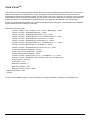
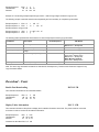
Document Revision History
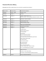
Document Title: APEX and ANDES Series Printer Command Language Developer’s Manual
Revision Date
Revision History
Revisions Since Last Issue
7/25/2008
Revision A Draft
First Issue - Draft
9/10/2008
Revision A
First Issue
10/10/2008
Revision B
Updated to firmware version 1.0.1
Added “Download – Self-test Message Hardware Information” section
01/28/2009
Revision C
Added Apex 4 printer information
02/03/2009
Revision D
Updated Dipswitch Table
02/11/2009
Revision E
Added Print Battery Voltage
02/23/2009
Revision F
Added Logo Download Example
02/25/2009
Revision G
Updated Page Print Pages
05/06/2009
Revision H
List Updates:
Esc @ description ,
Barcode Height Command
Form Feed Length
Forward Seek
Black Mark Sensing Auto Mode
Pass-Thru notes and examples
Printer Status LED Panel, Error/Warning LED Panel
Label Presenter Positive Adjust
BT Communications
Infrared Communications
WiFi Communications
USB Communication
Select Load Operating Mode
Dip Switch Settings Table: Added Footnotes
Esc a n command definition and example
10/03/2009
Revision I
Multiple corrections:
"Download - Printer Default Setup"
"Download – Self test Message Hardware Information"
2/16/2010
Revision J
Change to Datamax-O’Neil brand
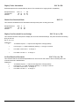
CONTENTS
Introduction ......................................................................................................................................................... 1
Datamax-O’Neil Printer Command Language (ExPCL) ................................................................................... 1
Communications................................................................................................................................................. 2
Character Sets .................................................................................................................................................... 3
Character Size and Line Spacing ...................................................................................................................... 3
Character Size and Line Spacing – Width and Height .................................................................................... 5
Character Attributes ........................................................................................................................................... 6
Horizontal Position ............................................................................................................................................. 8
Vertical Position.................................................................................................................................................. 9
Bar Codes .......................................................................................................................................................... 10
Code 39 Specifications ................................................................................................................................. 11
Code 128 Specifications ............................................................................................................................... 12
UCC/EAN-128 Specifications ....................................................................................................................... 13
Interleaved 2 of 5 Specifications ................................................................................................................... 14
UPC/EAN/JAN Specifications ....................................................................................................................... 14
Codabar Specifications ................................................................................................................................. 15
PDF 417 Specifications ................................................................................................................................ 16
Graphics ............................................................................................................................................................ 18
Printer Controls – Data Processing ................................................................................................................ 19
Printer Controls – Printed Output Adjust ....................................................................................................... 20
Printer Controls - Reset ................................................................................................................................... 21
Printer Controls – Power.................................................................................................................................. 21
Printer Status Commands ................................................................................................................................ 23
Magnetic Card Reader ...................................................................................................................................... 24
Black Mark Sensing Control Commands ....................................................................................................... 26
Black Mark Sensing Command Mode ............................................................................................................. 27
Black Mark Sensing Auto Mode ...................................................................................................................... 27
i
Page Print Commands - Configuration ........................................................................................................... 29
Page Print Commands – Draw Commands .................................................................................................... 30
Form FiestaTM .................................................................................................................................................... 33
Download - Printer Default Setup .................................................................................................................... 34
Download – Self test Message Hardware Information .................................................................................. 35
Download – Logo .............................................................................................................................................. 36
Download – Fonts ............................................................................................................................................. 37
Important Font Downloading Notes: ............................................................................................................... 40
Bluetooth™ & WiFi Setup Command ............................................................................................................. 42
Emulation .......................................................................................................................................................... 43
O’Neil Line Print mode .................................................................................................................................. 43
Communications Settings ............................................................................................................................... 45
Dip Switch Settings ....................................................................................................................................... 45
Serial Communication (RS232C) ..................................................................................................................... 46
USB Communication (USB) ............................................................................................................................. 47
Bluetooth™ Communications ......................................................................................................................... 48
Infrared Communications (Option) ................................................................................................................. 49
Wi-Fi Communication (Option) ........................................................................................................................ 50
Printer Status Indicator LED Panel ................................................................................................................ 50
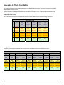
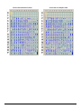
Appendix A: Flash Font Tables ....................................................................................................................... 52
ii
Introduction
This manual is intended to be used by software developers and system integrators with the purpose of developing applications
that can print output results using Datamax-O’Neil wide range of mobile thermal printers. This section of the manual describes
the various printer models, their main technical specifications and the communication interfaces available for each model. For
specific information about the operation of each printer refer to the User’s Guide.
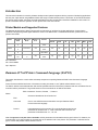
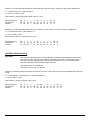
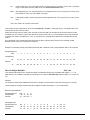
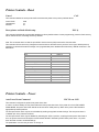
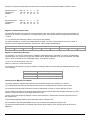
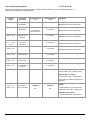
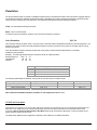
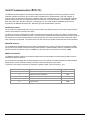
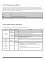
Printer Models and Supported Features
The Datamax-O’Neil series of thermal printers offer a wide variety of solutions for printing applications. Communication
interfaces and supporting flexible paper widths are shown in the table below. For additional information, please refer to the
printer’s User Guide.
Model
Max Paper
Width
APEX2
2.28”/58m
m
APEX3
Max. Print
Width
Communication Interfaces
Max Print
Dots
Sensors
RS-232
USB
BT
IrDA
WiFi
MCR
SCR
1.89”/48mm
384
Front Black
Mark
Std
NA
Std
Opt
Opt
Opt
Opt
3.15”/80m
m
2.83”/72mm
576
Front Black
Mark
Std
NA
Std
Opt
Opt
Opt
Opt
ANDES3
3.15”/80m
m
2.83”/72mm
576
Front & Back
Black Mark
Std
Std
Opt*
Std
Opt*
Opt*
Opt*
APEX4
4.35”/110.6
mm
4.09”/104m
m
832
Front Black
Mark
Opt
Std
Std
Opt
Opt
Opt
Opt
Std = Standard
NA = Not Available
Opt = Optional
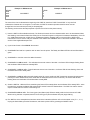
Datamax-O’Neil Printer Command Language (ExPCL)
This section describes the control codes and escape sequences comprising Datamax-O’Neil Printer Command Language
(ExPCL).
Control characters defined as the set of characters encoding from 0x00 to .0x1F (ASCII values between 0 to 31)
The ExPCL defines commands that start with the ESC (Hexadecimal 1B or Decimal 27) character and then are followed for the
command and the parameters. The general structure of the commands can be defined as follows:
ESC <Command> <Param1, Param2, ....,Param n>
Where:
Character Hexadecimal 1B or Decimal 27
ESC
Command
One or more ASCII characters that define a unique Datamax-O’Neil
Printer Command Language
Param1
Input parameters for the command. The commands that accept just one
parameter will be defined as “n” while commands with more than one
parameter will be defined as “n1”, “n2”, etc.
Note that spaces are not part of the commands and the parameters are indicated as items typed in italics. For instance, the
command ESC k n is used to select the character size of the resident fonts in the printers. The parameter n indicates the font
type to choose with possible values between o and 9.
1
Parenthesis is not part of the command unless specified otherwise:
For example Esc K n CR
Escape Sequence:
Hexadecimal:
Decimal:
ESC K
1B 4B
27 75
1
31
49
CR
0D
13
Note that CR means Carriage Return control character.
The following pages describe Datamax-O’Neil Command Language (ExPCL) components in more details. The commands have
been grouped based on major functions.
Communications
This section describes various methods of controlling the flow of data to and from the printer. The set of control characters
described below are used by the printer and the host while a communicating process is in place. Note that some handshaking
methods are only supported by the RS-232C Serial interface and are not supported for the USB, IrDA, Bluetooth, or Wi-Fi
interfaces.
End of Transmission
EOT
The printer sends an EOT character each time the printer’s input buffer becomes empty (indicating that the printer is idle).
Control Code:
Hexadecimal:
Decimal:
EOT
04
4
Note that this control character can be enabled and disabled using the command ESC P n. See detailed description of the
command in Section: “Printer Control: Data Processing”.
Transmitter On
XON
When selected XON/XOFF as flow control method of serial communication, this character is transmitted by the printer to indicate
that the printer is on line and ready to receive data. After receiving this character the host computer will start sending data to the
printer.
Control Code:
Hexadecimal:
Decimal:
XON
11
17
Transmitter Off
XOFF
When selected XON/XOFF as flow control method of serial communication, this character is transmitted by the printer to indicate
that the printer’s buffer is nearly full and that the host computer should stop sending data. The communication process is
reestablished after the printer transmits XON character to the host.
Control Code:
Hexadecimal:
Decimal:
XOFF
13
19
2
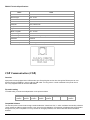
Character Sets
Select Character Set
Esc F n
This command will select the character set that will be used when printing extended characters (Hexadecimal: 80 to FF;
Decimal: 128 to 255).
n
1
2
A
Character Set
International Character Set
PC Line Drawing Character Set
16 bit font (Asian tables)
Example1: The following escape sequence will select the International character set.
Escape Sequence:
Hexadecimal:
Decimal:
ESC F
1B 46
27 70
1
31
49
Refer to Appendices Section for complete list of characters contained in each character set.
Note that printers are set to International Character Set by default. When using the PC Line Drawing Character Set, the text line
spacing should be set to zero in order to create continuous vertical lines.
This command is used in conjunction with the command ESC k n (or Esc K n, refer to Character Size and Line Spacing).
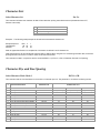
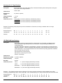
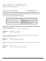
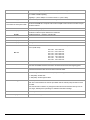
Character Size and Line Spacing
Select Character Pitch: Mode 1
ESC K n CR
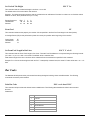
This command sets the font size based on the number of character per inch. The parameter n can have the following values:
n
0
1
2
3
4
5
6
7
8
9
10
11
12
13
14
15
Character Pitch/Font
~13 cpi Rotated / Courier mode 0
~12 cpi Normal / Courier mode 1
~16 cpi Normal / Courier mode 2
~19 cpi Normal / Courier mode 3
~21 cpi Normal / Courier mode 4
~24 cpi Normal / Courier mode 5
~10 cpi Normal / Monospace 821BT
~20 cpi Normal / Monospace 821BT
~20 cpi Bold / Monospace 821BT
~20 cpi Short / Monospace 821BT
~4 cpi Bold
~25 cpi Verin
~22 cpi Verin
~20 cpi Verin
~16 cpi Verin
~12 cpi Verin
Character size
Columns Per Line
16 x 14
16 x 23
12 x 23
10 x 23
09 x 23
08 x 23
20 x 23
10 x 23
10 x 23
10 x 18
48 x 80
08 x 23
09 x 23
10 x 23
12 x 23
16 x 23
3
APEX2
APEX3 / Andes3
APEX4
24 (rows/line)
24
32
38
42
48
19
38
38
38
8
48
42
38
32
24
36 (rows/line)
36
48
57
64
72
28
57
57
57
12
72
64
57
48
36
52 (rows/line)
52
69
83
92
104
40
80
80
80
17
104
92
83
69
52
This command (ESC K n CR) must be sent prior to any printable characters on the line in order to take effect.
Example 1: The following escape sequence set the pitch to 12 CPI (Courier Font):
Escape Sequence:
Hexadecimal:
Decimal:
ESC K
1B 4B
27 75
1
31
49
CR
0D
13
Example 2: The following escape sequence set the pitch to 25 CPI Verin Font:
Escape Sequence:
Hexadecimal:
Decimal:
ESC K
1B 4B
27 75
1
31
49
1
31
49
CR
0D
13
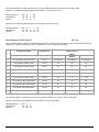
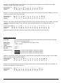
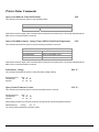
Select Character Pitch: Mode 2
ESC k n
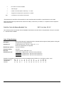
This command is used for backward compatibility when Legacy or Factory fonts are selected. The command sets the font size
based on the number of character per inch. The parameter n can have the following values:
Character Pitch/Font
Character size
Columns Per Line
n
APEX 2
APEX 3
Andes3
APEX4
0
~13 cpi Rotated / Courier mode 0
16 x 14
24 (rows/line)
36 (rows/line)
52 (rows/line)
1
~12 cpi Normal / Courier mode 1
16 x 23
24
36
52
2
~16 cpi Normal / Courier mode 2
12 x 23
32
48
69
3
~19 cpi Normal / Courier mode 3
10 x 23
38
57
83
4
~21 cpi Normal / Courier mode 4
09 x 23
42
64
92
5
~24 cpi Normal / Courier mode 5
08 x 23
48
72
104
6
~10 cpi Normal / Monospace 821BT
20 x 23
19
28
40
7
~20 cpi Normal / Monospace 821BT
10 x 23
38
57
80
8
~20 cpi Bold / Monospace 821BT
10 x 23
38
57
80
9
~20 cpi Short / Monospace 821BT
10 x 18
38
57
80
This command (ESC k n) must be sent prior to any printable characters on the line in order to take effect.
Example: The following escape sequence set the pitch to 12 CPI (Courier font):
Escape Sequence:
Hexadecimal:
Decimal:
ESC k
1
1B 6B 31
27 107 49
4
Character Size and Line Spacing – Width and Height
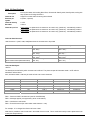
Double Wide ON
SO
This command sets any printed characters to double wide.
Control Code:
Hexadecimal:
Decimal:
SO
0E
14
Double Wide OFF
SI
This command disables the double wide feature.
Control Code:
Hexadecimal:
Decimal:
SI
0F
15
Double High ON
FS
This command enables double high printing. The characters printed after this control character will be printed as double height
and also the interline spacing is doubled in height. This feature will be disabled using the control character GS. Refer to the
“Double High OFF” control character for more details.
Control Code:
Hexadecimal:
Decimal:
FS
1C
28
Double High OFF
GS
This command disables double high printing.
Control Code:
Hexadecimal:
Decimal:
GS
1D
29
Set Text Line Spacing
ESC a n
This command sets the line spacing between successive printed text lines (dot row). Each dot row is 0.125mm.
0 ≤ n ≤ 40 ) decimal= . If n value is greater than 0x28 or Decimal 40, then n will be set to 0x28 )Decimal 40).
Example: The following escape sequence sets the line spacing to zero (as needed when printing line drawing characters when
the PC Line Drawing character set is selected).
Escape Sequence:
ESC a NUL
Hexadecimal:
1B 61 00
Decimal:
27 97
0
Example 2: The following escape sequence sets the line spacing to 40 dot lines (0x28 and Decimal 40)
Escape Sequence:
ESC a
(
Hexadecimal:
1B 61 28
Decimal:
27 97 40
Note 1: Printer’s default settings are set to 3-dot line after each text line.
Note 2: Line spacing must be set to zero when printing PC Line-Draw characters, the, thus allowing graphic characters on
successive lines to be connected.
5
Character Attributes
Emphasized Printing Mode
ESC U n
The Emphasized printing mode command will cause the printer to print text with bold appearance.
n
0
1
Selection
Emphasized Mode Off
Emphasized Mode On
Note that on power up the printer defaults to emphasized mode off.
Example1: The following escape sequence will enable the Emphasized printing mode.
Escape Sequence:
Hexadecimal:
Decimal:
ESC U
1B 55
27 85
1
31
49
All characters following this command will be emphasized. The emphasized command is terminated either by the Esc U
0 command or by cycling the printer power.
Example 2: The following escape sequence will disable the emphasized printing mode.
Escape Sequence:
Hexadecimal:
Decimal:
ESC U
1B 55
27 85
0
30
48
Underline Printing Mode
ESC U n
Underline printing mode may be used to underline text.
n
U
u
Selection
Underline Mode ON
Underline Mode OFF
Note that on power up the printer defaults to underline mode off.
Example1: The following escape sequence will enable the underline printing mode.
Escape Sequence:
Hexadecimal:
Decimal:
ESC U
1B 55
27 85
U
55
85
All characters following this command will be underlined. The underline command is terminated either by the Esc U u
command or by cycling the printer power.
Example 2: The following escape sequence will disable the underline printing mode.
Escape Sequence:
Hexadecimal:
Decimal:
ESC U
u
1B 55 75
27 85 117
6
Reverse Print
ESC U n
The reverse print command enables the user to print white letters on a black background .Reverse printing begins with the
characters following the command.
n
R
n
Selection
Reverse printing ON
Reverse printing OFF
Note that on power up the printer defaults to reverse printing off.
Example1: The following escape sequence will enable the reverse printing mode.
Escape Sequence:
Hexadecimal:
Decimal:
ESC U
1B 55
27 85
R
52
82
All characters following this command will be reverse printed. The reverse printing command is terminated either by the Esc U n
command or by cycling the printer power.
Example 2: The following escape sequence will disable the reverse printing mode.
Escape Sequence:
Hexadecimal:
Decimal:
ESC U
n
1B 55 6E
27 85 110
Right to Left and Left to Right Printing
ESC F n
This command causes the printer to change the direction in which characters are printed. The printer direction default mode is
set to Left to Right.
n
R
L
Selection
Right to Left
Left to Right
Note that on power up the printer defaults to left to right printing mode.
Example1: The following escape sequence will enable the right to left printing mode.
Escape Sequence:
Hexadecimal:
Decimal:
ESC F
1B 46
27 70
R
52
82
All characters following this command will be printing right to left printed. The right to left printing command is
terminated either by the Esc F L command or by cycling the printer power.
Example 2: The following escape sequence will disable the left to right printing mode.
Escape Sequence:
Hexadecimal:
Decimal:
ESC F
1B 46
27 70
L
4C
76
7
Horizontal Position
Carriage Return
CR
This command prints the input buffer information and advances the paper to the next line. If the printer buffer is empty a line is
advanced.
Control Code:
Hexadecimal:
Decimal
CR
0D
13
Backspace
BS
This command removes the previous character from the print buffer.
Control Code:
Hexadecimal:
Decimal:
BS
08
8
Horizontal Tab
HT
This command advances the cursor by the number of dots specified in the Horizontal Margins command
Control Code:
Hexadecimal:
Decimal:
HT
09
9
Set Horizontal Tab Width
ESC T H n
This command sets the Horizontal Tab (HT) value. The parameter n has values between 0 and 255 with a default value of 100
dots..
Example: The following escape sequence sets the horizontal tab width to 50 dots.
Escape Sequence:
Hexadecimal:
Decimal:
ESC T
1B 54
27 84
H
48
72
2
32
50
8
Vertical Position
Line Feed
LF
This command prints the input buffer information and advances the paper to the next line.
Total Feed Length = Vertical size of the current font + Text Line Spacing
A Carriage Return (CR) is also performed to place the current print position at the beginning of the next line.
Control Code:
Hexadecimal:
Decimal :
LF
0A
10
Variable Size Line Feed
ESC J n
This command moves the paper forward as per the distance specified by the parameter n x 0.125mm. 0 ≤ n ≤ 255.
A Carriage Return (CR) is also performed to place the current print position at the beginning of the next line.
Example: The following escape sequence advances the paper ten millimeters. Each dot is 0.125mm so to advance the paper
10mm, the n parameter is 80 (10 / 0.125).
Escape Sequence:
Hexadecimal:
Decimal:
ESC J
1B 4A
27 74
P
50
80
Variable Size Reverse Line Feed
ESC Q J n
This command moves the paper in reverse direction as per the distance specified by the parameter n x 0.125mm. 0 ≤ n ≤ 255.
A Carriage Return (CR) is also performed to place the current print position at the beginning of the next line.
Example: The following escape sequence moves the paper in the reverse direction ten millimeters. Each dot is 0.125mm so to
reverse the paper 10mm, the n parameter is 80 (10 / 0.125).
Escape Sequence:
Hexadecimal:
Decimal:
ESC Q
1B 51
27 81
J
4A
74
P
50
80
Vertical Tab
VT
This command advances the cursor the number of dot lines specified in the Vertical Margin command (below).
A Carriage Return (CR) is also performed to place the current print position at the beginning of the next line.
Control Code:
Hexadecimal:
VT
0B
9
Set Vertical Tab Height
ESC T V n
This command sets the vertical tab length in dot lines. 0 ≤ n ≤ 255.
The default value of the vertical tab is 203 dot lines.
Example: The following escape sequence sets the vertical tab to ten millimeters. Each dot is 0.125mm so to fixed the vertical
distance of 10mm, the n parameter is 80 (10 / 0.125).
Escape Sequence:
Hexadecimal:
Decimal:
ESC T
1B 54
27 84
V
56
86
P
50
80
Form Feed
FF
This command advances the paper by the number of lines specified in the Set Form Feed length in dot lines (below).
A Carriage Return (CR) is also performed to place the current print position at the beginning of the next line.
Control Code:
Hexadecimal:
Decimal
FF
0C
12
Set Form Feed Length in Dot Lines
ESC T F n1 n2
This command sets the Form Feed Length in Dot Lines. The total Form Feed distance is computed using the following formula:
(n2 * 256 + n1). 0 ≤ n1 ≤ 255. 0 ≤ n2 ≤ 255. The default value is 1030 dot lines.
Note that the height of the font in dot lines will be subtracted from the total dot lines specified in the command.
Example: For a font 23 dot lines high and with an Esc T V 200 (0xC8) command sent, the actual VT value will be 200 – 23 = 177
dots.
Bar Codes
The Datamax-O’Neil printer series print several barcode symbologies including Linear and 2D barcodes. The following
commands are used to print barcodes.
Print Bar Code
ESC z t n h data CR LF
This command will print a barcode without human readable text. The following table describes the Bar Code command
structure.
Parameters:
t
Barcode
1
Code 39
2
Code 128,UCC/EAN-128
3
Interleaved 2 of 5
4
UPC/EAN/JAN
5
Codabar
9
PDF417 *
10
z
bar code is non-human readable
t
barcode type.
n
number of character bytes in data array. 1 ≤ n ≤ 255
h
height of bar code printed in increments of 0.125mm
data
n characters to be encoded in the barcode.
*The parameters for the PDF417 barcode differ from the Linear Barcodes. See PDF-417 specifications for more detail.
Note that all barcodes are printed with the minimum bar width (“x-dimension”) of 0.250mm, in compliance with the respective
official specification.
Print Bar Code with Human Readable Text
ESC Z t n h data CR LF
This command prints a barcode with Human Readable Text below the barcode. Refer to the parameters of the prior command.
Z
Indicates human readable
Code 39 Specifications
Description
Each symbol starts with Leading Quiet Zone, followed with Start Symbol, Data Symbols, ending with
Stop Symbol and Trailing Quiet Zone
Character set
36 alphanumeric (0-9, A-Z) and '-' 'space' '$' '/' '+' '%'
Note: Only capital letters are supported.
Elements per symbol:
9 (5 bars, 4 spaces)
Character density
6.25 CPI
Bar width
0.25mm (narrow to wide ratio of 1:3).
Characters per line
2 Inch printer: 9 alphanumeric with auto center (maximum)
3 Inch printer: 12 alphanumeric with auto center (maximum)
4 Inch printer: 22 alphanumeric with auto center (maximum)
Example: The following command will print human readable barcode “CODE 39” of 1mm high (0.125*8= 1mm).
Escape Sequence:
Esc Z
1
7
8
C
O
D
E
3
9 CR LF
Hexadecimal:
1B 5A 31 07 08 43 4F 44 45 2D 33 39 0D 0A
Decimal:
27 90 49
7
8
67 79 68 69 45 51 57 13 10
11
Code 128 Specifications
Description
Each symbol starts with Leading Quiet Zone, followed with Start Symbol, Data Symbols, ending with
Stop Symbol and Trailing Quiet Zone
Character set
Support for full 256 ASCII set among three subsets
Elements per
symbol
6 (3 bars, 3 spaces)
Character density
9.1 CPI
Bar width
0.25mm
Characters per line
2 Inch printer: 13 alphanumeric characters or 26 numeric only (maximum) - automatically centered
3 Inch printer: 18 alphanumeric characters or 36 numeric only (maximum) - automatically centered
4 Inch printer: 32 alphanumeric characters or 36 numeric only (maximum) - automatically centered
Code 128 Start Character:
<start character> = {0x87, 0x88, 0x89} determines the character set to be printed
Start Character
Characters Sent to Printer
Characters Read by Bar Code Reader
IF <start character> is 0x87 CODE A
0x020 through 0x03F ASCII
(#32 - #63)
0x020 through 0x03F ASCII
(#32 - #63)
0x040 through 0x07F ASCII
(#64 - #127)
0x020 through 0x07F ASCII
(#32 - #127)
PAIRS 0x030 through 0x039 ASCII
(#48 - #57)
0x00 through 0x07F ASCII
(#0 - #31)
0x020 through 0x07F ASCII
(#32 - #127)
PAIRS 0x030 through 0x039 ASCII
(#48 - #57)
IF <start character> is 0x88 CODE B
IF <start character> is 0x89 CODE C
(Each number must be paired with another)
Code 128 Data Bytes:
<DATA>
The data bytes are defined by which character set is defined. The printer accepts all characters 0x20h - 0x7Fh with the
translations defined above.
Also, characters 0x080 - 0x86 may be used as Code 128 control characters:
HEX
0x080
0x081
0x082
0x083
0x084
0x085
0x086
DEC
128
129
130
131
132
133
134
CODE A
FNC 3
FNC 2
SHIFT
change to C
change to B
FNC 4
FNC 1
CODE B
FNC 3
FNC 2
SHIFT
change to C
FNC 4
change to A
FNC 1
CODE C
change to B
change to A
FNC 1
FNC 1: Reserved CODE 128 character (used for UCC/EAN128)
FNC 2: Message append (not supported by all bar code readers)
FNC 3: Initialize bar code reader
FNC 4: Extend characters (bar code reader reads character + 128)
For example: 'a' is changed from #97 to #97+128 = #225
Note that it is possible to switch code sets in the middle of the bar code. This is useful with heavily numeric alphanumeric bar
codes (see example below).
12
Example 1: The following escape sequence prints alphanumeric bar code "A2a", 12.5mm high, with human readable text:
n = 3 printed characters + 1 start character = 4
L = 12.5mm / 0.125mm = #100
start character = START B (full ASCII alpha numeric) = #136
Escape Sequence:
Hexadecimal:
Decimal:
Esc Z
1B 5A
27 90
2
32
50
4
d
88 A
04 64 88 41
4 100 136 65
2
32
50
a
60
97
CR
0D
13
LF
0A
10
Example 2: The following escape sequence print all-numeric bar code "1234", 5mm high, non-human readable text:
n1 = 4 printed characters + 1 start character = 5
L = 5mm / 0.125mm = #40
start character = START C (numeric pairs) = #137
Escape Sequence:
Hexadecimal:
Decimal:
Esc z
2
1B 7A 32
27 122 50
5
05
5
(
89
1
28 89 31
40 137 49
2
32
50
3
33
51
4
34
52
CR
0D
13
LF
0A
10
UCC/EAN-128 Specifications
Description
The UCC/EAN-128 specification is an internationally recognized format for application identifiers in
code 128 bar codes. The bar code symbology is identical to Code 128. These identifiers are not
intended for point-of-sale applications. Only recognized bodies of the UCC or EAN may assign
application identifiers. More information may be found at:
http://www.ean.be/ for the EAN and
http://www.uc-council.org/ for the UCC
Example: The following escape sequence print all-numeric bar code "1234", 5mm high, with human readable text in EAN-128
format:
n1 = 1 start character + EAN specified + 4 printed characters = 6
L = 5mm / 0.125mm = #40
start character = START C (numeric pairs) = #137
Escape Sequence:
Hexadecimal:
Decimal:
Esc Z
1B 5A
27 90
2
32
50
6
06
6
(
89 FNC1 1
28 89 86 31
40 137 134 49
13
2
32
50
3
33
51
4
34
52
CR
0D
13
LF
0A
10
Interleaved 2 of 5 Specifications
Description
Each symbol starts with Leading Quiet Zone, followed with Start Symbol, Data Symbols, ending with
Stop Symbol and Trailing Quiet Zone
numeric pairs
Character set
Elements per
symbol
10 (5 bars, 5 spaces)
Character density
1.11 CPI
Bar width
25mm
Characters per line
2 inch printer: 16 numeric (maximum), automatically centered
3 inch printer: 24 numeric (maximum), automatically centered
4 inch printer: 35 numeric (maximum), automatically centered
Example: The following escape sequence prints an Interleaved 2 of 5 barcode, encoding “12345678” with 10 mm high,
human readable.
Escape Sequence:
Esc
Z
3
8
2
1
2
3
4
5
6
7
8
CR
LF
Hexadecimal:
1B
5A
33
08
32
31
32
33
34
35
36
37
38
0D
0A
Decimal:
27
90
51
8
50
49
50
51
52
53
54
55
56
13
10
UPC/EAN/JAN Specifications
Description
Each symbol starts with Leading Quiet Zone, followed with Left Guard Bars, Left Data Symbols,
Center Bar Pattern, Right Data Symbols, Check Character, ending with Right Guard Bars and
Trailing Quiet Zone.
The UPC, EAN/JAN-8, EAN/JAN-13 specifications comprise an internationally recognized format for
application identifiers. Unlike the UCC/EAN-128 specification, these identifiers are intended for pointof-sale applications. Only recognized bodies of the UCC and EAN may assign application identifiers.
More information may be found at:
http://www.ean.be/ for the EAN and
http://www.uc-council.org/ for the UCC
Numeric - fixed length
Character set
Elements per symbol
4 (2 bars, 2 spaces)
Character density
14.5 CPI
Bar width
0.25mm
Characters per line
UPC-A:
11 - plus check digit (automatically centered)
UPC-E:
6 - plus check digit (automatically centered)
EAN/JAN-8: 7 - plus check digit (automatically centered)
EAN/JAN-13: 12 - plus check digit (automatically centered)
Example 1: The following escape sequence will print a UPC-A bar code with the following: human readable, 30 mm high,
containing “123456789012” where 2 is the check digit. Due to limited spacing CR LF are not shown at the end of this command.
Escape Sequence:
Hexadecimal:
Decimal:
ESC Z
1B 5A
27 90
4
34
52
12 240 1
0C F0 31
12 240 49
2
32
50
3
33
51
14
4
34
52
5
35
53
6
36
54
7
37
55
8
38
56
9
39
57
0
30
48
1
31
49
Example 2: The following escape sequence will print a UPC-E bar code with the following: human readable, 30 mm high,
containing “1234565” where 5 is the check digit.
Escape Sequence:
Hexadecimal:
Decimal:
ESC Z
1B 5A
27 90
4
34
52
7 240 1
07 F0 31
7 240 49
2
32
50
3
33
51
4
34
52
5
35
53
6
36
54
CR
0D
13
LF
0A
10
Example 3: The following escape sequence will print an EAN/JAN-8 bar code with the following: human readable, 30 mm high,
containing “12345670” where 0 is the check digit.
Escape Sequence:
Hexadecimal:
Decimal:
ESC Z
1B 5A
27 90
4
34
52
8 240 1
08 F0 31
8 240 49
2
32
50
3
33
51
4
34
52
5
35
53
6
36
54
7
37
55
CR
0D
13
LF
0A
10
Example 4: The following escape sequence will print an EAN/JAN-13 bar code with the following: human readable, 30 mm high,
containing “1234567890128” where 8 is the check digit. Due to limited spacing CR LF are not shown at the end of this
command.
Escape Sequence:ESC Z
Hexadecimal:
1B 5A
Decimal:
27 90
4
34
52
13 240 1
0D F0 31
13 240 49
2
32
50
3
33
51
4
34
52
5
35
53
6
36
54
7
37
55
8
38
56
9
39
57
0
30
48
1
31
49
2
32
50
Note that all heights are total height, including a 1.23mm drop bar pattern printed after the bar code pattern.
Codabar Specifications
Description
Each symbol starts with Leading Quiet Zone, followed with Start Symbol, Data Symbols, ending with
Stop Symbol and Trailing Quiet Zone
Character set
0-9, {$, -, :, /, ., +} and start/stop pairs {A/T, B/M, C/*, D/E}
Elements per
symbol
7 (4 bars, 3 spaces)
Character density
8.1 CPI
Bar width
0.25mm
Characters per line
2 Inch Printer: 15 (maximum) plus start/stop, automatically centered
3 inch printer: 20 (maximum) plus start/stop, automatically centered
4 inch printer: 35 (maximum) plus start/stop, automatically centered
Example 1: The following escape command prints a Codabar barcode with the following: Encoding “123456”, human readable,
20 mm high, start character A and stop character T
Escape Sequence:
ESC Z
5
8 160 A
1
2
3
4
5
6
T CR LF
Hexadecimal:
1B 5A 35 08 A0 41 31 32 33 34 35 36 54 0D 0A
Decimal:
27 90 53
8 160 65 49 50 51 52 53 54 84 13 10
Example 2: The following escape command prints Codabar barcode with the following: Encoding “2468”, human readable, 10
mm high, start character C and stop character *. .
Escape Sequence:
Hexadecimal:
Decimal:
ESC Z
1B 5A
27 90
5
35
53
6
06
6
P
50
80
C
43
67
2
32
50
4
34
52
15
6
36
54
8
38
56
*
2A
42
CR
0D
13
LF
0A
10
PDF 417 Specifications
Description
Each PDF 417 symbol character consists of a stack of vertically aligned rows between 3 and 90. Each
row includes a start and a stop pattern, left and right row indicators and a maximum of 30 symbol
characters. The symbol shall include a quite zone on all four sides
Character set
All ASCII and extended characters, 8-Bit binary data and up to 811,800 different character sets
Elements per
symbol
Height: Variable (3 to 90 rows) and Width: Variable (90X to 583X)
Character/symbol
1850 text characters
Error correction
2 to 512
PDF417 Command Structure:
<ESC> – ‘z’ – ‘9’ – CM – SL – SW – SH – EW – EH – MSB – LSB – [User’s Data]
Parameters
CM:
Compaction Mode. Select a mode to encode the user’s data
Compaction Mode
Description
Encoding Capability
‘0’ (Future Use)
Byte Compaction Mode (BC)
All characters, (0-255)
‘1’ (Recommended)
Text Compaction Mode (TC)
ASCII only, (0-127) + Shift to BC Mode is implemented.
‘2’ (Future Use)
Numeric Compaction Mode (NC)
Digits Only, (‘0’-‘9’)
A’ (Future Use)
AUTO (combinations of all modes)
Mix of three compaction modes
SL:
Security Level byte. This can be any digit from ‘0’ to ‘8’. Set the value of the Security Level based on
the number of user’s data to be encoded
Security Level
# Error-Check Code Words
‘0’
‘1’
‘2’ (recommended)
‘3’
‘4’
‘5’
‘6’
‘7’
‘8’
2
4
8
16
32
64
128
256
512
SW:
Symbol Width byte. This is the total width length of the printed PDF417 symbol. The user may specify any value here,
and the printer will calculate the actual width of the symbol & it will update this value again (Future Use).
Recommended Value: ‘0’ or 0x30
SH:
Symbol Height byte. This is the total height length of the printed PDF417 symbol. The user may specify any value
here, and the printer will calculate the actual width of the symbol & it will update this value again (Future Use).
Recommended Value: ‘0’ or 0x30
EW:
Element Width byte. This is the width length of a single element in the PDF417 symbol, that is, bar/space width. Can
be set to ‘1’ or ‘2’
Element Width Value
‘1’
‘2’ (recommended)
Length in mil
4.9 mil
9.8 mil
16
EH:
Element Height byte. This is the height length of a single element in the PDf417 symbol, that is, bar/space
height. A value between 0x03 to 0x0A can be used. Recommended Value: 0x06
MSB:
Most Significant Byte: This byte represents the most significant byte of how many bytes to encode of User’s
Data. Maximum is 06 in hex, that is, MSB = 06h (max).
LSB:
Least Significant Byte: This byte represents the least significant byte of how many bytes to encode of user’s
Data.
User’s data: Data to be encoded in the barcode
Total number of user’s data that can be encode is [MSB][LSB] = 0x06B8 = 1720 bytes, that is, only alphanumeric with
security level set to its minimum value.
Setting the security level to a higher value, will result in less user data to be encoded, since the total number of code
words that can fit in a PDF417 symbol are 929, and if security level is set to ‘8’, then already 512 error code words are
occupied in the symbol, and (929-512 = 417), so only about (417*2) alphanumeric data can be encoded with security
level ‘8’.
If any parameter in the command line does not match the spec in this document, then an error message “Invalid
Barcode” will be sent out from the printer’s serial port.
Example: The following escape commands encode the data “12345678”. Due to space limitation CR LF are not shown
Escape Sequence:
ESC
z
9
1
2
0
0
2
6
0
8
1
2
3
4
5
6
7
8
1B
7A
39
31
32
30
30
32
06
00
08
31
32
33
34
35
36
37
38
27
122 57
49
50
48
48
50
6
0
8
49
50
51
52
53
54
55
56
Hexadecimal :
Decimal:
Barcode Height Multiplier
ESC z h n
This command allows the user to change the height of a selected barcode using a multiplier with values 1 < n < 18
(HEX values). The multiplier command can be sent prior to or after the Print Barcode sequence (ESC z t n h data CR
LF)
Example:
The sequence below prints CODE39 barcode first of a height of 50 dots and then sets the new height to 3 x 50 dots.
To print CODE-39 of height 150 dots using the multiplier command send steps 1, 2, in the order below.
Barcode Height Multiplier
Escape Sequence:
Hexadecimal:
Decimal:
ESC z
h
3
1B 7A 68 03
27 122 104 3
Printing Barcode:
Escape Sequence:
Hexadecimal:
Decimal:
Esc Z
1B 5A
27 90
1
31
49
7
07
7
2
32
50
C
43
67
O
4F
79
D
44
68
17
E
45
69
2D
45
3
33
51
9
39
57
CR
0D
13
LF
0A
10
Graphics
The printer uses a single line thermal print head with elements spaced at 0.125mm. The 8-bit graphic commands
enable control of each heating element of the print head. The commands also advance the paper in increments of
0.125mm. The number of heating elements can vary according to your printer model. Refer to the printer’s User’s Guide
for specific information.
To select the 8-bit graphic mode, the user application must issue the ESC V command. After that, the user application
must send two bytes to indicate the number of the graphic lines desired, followed with a packet of 72 bytes for each
graphic line. The printer prints the graphic line and advances to the next line automatically.
8-Bit Graphics
ESC V n1 n2 data
8-bit Graphic mode is selected using the ESC V command. <n1> and <n2> is a 16 bit integer indicating the number of
graphic lines of 72 characters each to be received. Valid Graphic character sets range from 0x00 to 0xFF Hex using bits
0-7
To achieve optimized smooth printing and to extend battery life when printing graphics, a print buffer is employed. The
printer buffer accumulates a specific amount of data before actually printing the graphic data.
The following 8-bit graphic command is used to print a single line of graphic
Escape Sequence:
Hexadecimal:
Decimal:
ESC
1B
27
V SOH NUL
72 bytes of data
56
86
72 bytes of data
72 bytes of data
01
1
00
0
8 Bit Compressed Graphics
ESC v height width counter data [c data] [c data] …
This command differs from the 8 Bit Graphics command described above by reducing the number of bits (bytes) that
have to be sent to the printer. This allows for faster data transfer between the host computer and the printer.
Graphic String Component
height
(# of lines)
width
(# of bytes in each line)
Function
An eight bit value representing the number of dot-lines contained in the following data set
An eight bit value representing the number of bytes to be contained in each dot-line of the following
data set
An eight bit value which describes how the following data will be processed
counter
r (# of lines)
For Signed
Values
{127 ≥ Counter ≥ 0} Process the next (Counter + 1) bytes of data as 8 bit
graphics.
{0 > Counter ≥ -128} Repeat the next single byte of data ((-Counter) + 1) times.
For Unsigned
Values
{127 ≥ Counter ≥ 0} Process the next (Counter+1) bytes of data as 8 bit graphics
{128 ≥ Counter ≤ 255} Repeat the next Singe byte of data, (( 256 – Counter)+1)
times
Example: Compressed graphic
The following graphics data is to be printed:
18
This data may be represented in hexadecimal:
0x55
0x55
0x00
0x00
0xAA
0x11
0x55
0x00
0x55
0x55
0x55
0x55
The RLE compressed graphics command:
DEC
HEX
width counter data…
ESC
‘v’
height
27
118
2
6
255
85
0x02
0x06
0xFF
0x55
0x1B 0x76
255
0
3
170
17
85
0
253
0xFF 0x00 0x03 0xAA 0x11 0x55 0x00 0xFD
85
0x55
Printer Controls – Data Processing
The printer can be operated in two modes, Online and Buffer mode. In online mode, the characters are printed as they are
received. In buffer mode, the characters received are stored in the print buffer and printed upon receipt of the EOT character
(^D). Also if the printer is in Buffer Mode and the print buffer is full, the printer will start printing but will remain in the Buffer Mode
until the Online Mode command is sent to the printer.
Enable Buffer Mode
ESC P $
This command selects the printer buffer mode.
Escape Sequence:
Hexadecimal:
Decimal:
ESC P
1B 50
27 80
$
24
36
Disable Buffer Mode (Select Online Mode)
ESC P #
This command disables the printer buffer mode and selects the online mode. The online mode is the default mode of operation
of the printer.
Escape Sequence:
Hexadecimal:
Decimal:
ESC P
1B 50
27 80
#
23
35
19
Print Buffer Contents (Buffer Mode)
EOT
This command allows the printer to process all of the commands stored in the printer buffer. This command is valid only when
the printer is in the buffer mode.
Control Code:
Hexadecimal:
Decimal
EOT
04
04
Enable EOT Control Character Transmission (Currently Not Available)
ESC P +
When enabled, the printer transmits the EOT command character when the print buffer is empty. The End Of Text (EOT) control
character is transmitted once when the printer buffer is empty.
Escape Sequence:
Hexadecimal:
Decimal:
ESC P
1B 50
27 80
+
2B
43
Disable EOT Control Character Transmission (Currently Not Available)
ESC P –
This command disables the EOT control character transmission. Therefore, the control character EOT is not transmitted when
the printer buffer is empty
Escape Sequence:
Hexadecimal:
Decimal:
ESC P
1B 50
27 80
2D
45
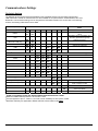
Printer Controls – Printed Output Adjust
Print Contrast
ESC P n
This command sets the printer level of contrast or darkness of the printer.
The parameter n is the level of contrast. 1 ≤ n ≤ 9.
The printed text or graphics contrast depends on the type of thermal paper used, the printer battery voltage and the
printer contrast setting (selected by the host application).
The table below specifies recommended n values according to the media used.
Paper type
P390
P300
Reserved (currently P300)
Low
1
4
7
Medium
2 (*)
5
8
* The printer defaults to a contrast of ‘2’.
Note that the print speed and power consumption is affected by the contrast setting.
Example: The following escape sequence set the printer contrast to “7”.
Escape Sequence:
Hexadecimal:
Decimal:
ESC P
1B 50
27 80
7
37
55
20
High
3
6
9
Printer Controls - Reset
Cancel
CAN
This command deletes the entire printer buffer and resets the printer to the power-up default values.
Control Code:
Hexadecimal:
Decimal:
CAN
18
24
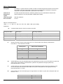
Reset printer and load default setup
ESC @
This command initializes all programmable attributes to factory default values. Custom programming, present in flash memory,
will be restored as well, overriding the factory defaults.
Note: This command does not clear the print buffer! Use the Cancel (CAN) command to clear the buffer.
This command will not restore any changes that were burned into the flash memory such as: fonts, logos, default power up
message or hardware information message. User programmable printer attributes and their factory defaults are shown in the
table below:
Attribute
Font
Character set
Underline
Bold
Reverse Printing (White on Black)
Double Width
Double Height
Line spacing
Form Feed Length
Vertical Tab distance
Horizontal Tab distance
Printing direction
Contrast
Sensor Sensitivity
Auto Power Down time
Factory Default
Courier 3
International
Disabled
Disabled
Disabled
Disabled
Disabled
3 dots
2030 dots
203 dots
100 dots
Left-to-right
2
255
99 seconds
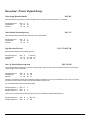
Printer Controls – Power
Auto Power Down Command
ESC M n m 0 CR
This command configures the printer Auto power-down timer.
In order to conserve battery life, the printer features an auto power down timer. If the printer is in the AUTO POWER
DOWN MODE, the power down timer defaults to 99 seconds on initial power up. Refer to the printer User Manual for
appropriate dip-switch positions.
The auto power down timer may be set or disabled by sending recognized command strings. The auto power down is
re-started upon every character received.
The auto power down timer may be disabled by activating the <RTS> input line, or setting the auto power down timer to
zero, the printer lowers the CTS output line and transmits AUXOFF followed by XOFF before power down. On power
down the timer reverts to its default settings.
The parameters n1 and n2 may be set to ‘0’ through ‘9’.
21
Example 1: The command Esc M 0 0 0 CR Disables the power out timer
Example 2: The command Esc M 9 9 0 CR Sets the timer to 99 seconds
Note that spaces are not part of the command
Extended Auto Power Down Command
ESC M HH MM SS 0 CR
The ‘Set Auto Power Down’ command allows the user to program the printer to automatically shut down after a certain
length of inactivity. This command accepts the following formats: (1) seconds, (2) minutes and seconds, or (3) hours,
minutes and seconds. When used in conjunction with the Default Power-Up Setup command, this command will allow
for the power down timer value to be saved permanently in Flash.
The following table details the available formats for this command:
Command String
Esc–‘M’–‘S1’ –‘S2’–‘0’–CR
Printer Response
Sets the printer Auto power down timer to S1S2
seconds
Sets the printer Auto power down timer to M1M2
minutes S1S2 seconds
Sets the printer Auto power down timer to H1H2
hours M1M2 minutes S1S2 seconds
Esc–‘M’–‘M1’–‘M2’–‘S1’ –‘S2’–‘0’–CR
Esc–‘M’–‘H1’–‘H2’–‘M1’–‘M2’–‘S1’ –‘S2’–‘0’–CR
Here, H1H2, M1M2 and S1S2 are two decimal characters that denote hours, minutes and seconds respectively. Values
range from ‘00’ to ‘99’ with values over 59 being carried over. Up to 18 hours may be specified. The CR character at the
end of the command is mandatory.
Example 1: This escape sequence sets the Auto power down timer to 54 seconds
Escape Sequence:
Hexadecimal:
Decimal:
ESC M
1B 4D
27 77
5
35
53
4
34
52
0
30
48
CR
0C
13
Example 2: This escape sequence sets the Auto power down timer to 1 hour 16 minutes 54 seconds. Note that 76
minutes was converted to 1 hour 16 minutes.
Escape Sequence:
Hexadecimal:
Decimal:
ESC M
1B 4D
27 77
7
37
55
6
36
54
5
35
53
4
34
52
0
30
48
CR
0C
13
Example 3: This escape sequence sets the Auto power down timer to 18 hours. Note that 98 hours got truncated to 18
hours
Escape Sequence:
Hexadecimal:
Decimal:
ESC M
1B 4D
27 77
9
39
57
8
38
56
7
37
55
6
36
54
5
35
53
4
34
52
22
0
30
48
CR
0C
13
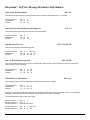
Printer Status Commands
Query Print Buffer & Timer-MCR Status
STX
This command will cause the printer to print the battery status
Print Buffer Status
Timer-MCR Status
Printer Response
ESC B <4 ASCII digits> CR LF
ESC M <4 ASCII digits> CR LF
Note that the first three digits of the Timer-MCR field correspond to the printer times. The last byte indicates that the
MRC track is currently activated in the printer.
Query Print Buffer, Battery Voltage, Timer-MCR & Print Head Temperature
SYN
This command will cause the printer to send the following information to the host:
Print Buffer Status
Battery Voltage Status
Timer-MCR Status
Print Head Temperature
Printer Response
ESC B <4 ASCII digits> CR LF
ESC V <4 ASCII digits> CR LF
ESC M <4 ASCII digits> CR LF
ESC T <4 ASCII digits> CR LF
Note that the first three digits of the Timer-MCR field correspond to the printer times. The last byte indicates that the
MRC track is currently activated in the printer.
Print Battery Voltage
ESC P ^
This command will enable the printer to output the battery voltage reading.
Escape Sequence:
Hexadecimal:
Decimal:
ESC P
1B 50
27 80
^
5E
94
Query Printer Firmware Version
ESC P (
This command will cause the printer to send the Firmware Version to the host.
Escape Sequence:
Hexadecimal:
Decimal:
ESC P
1B 50
27 80
(
28
40
After sending the previous command, the printer will respond with the following ASCII sequence:
ASCII Sequence:
<string>
CR
LF
The <string> field represents the firmware version.
23
Query Printer Model and Hardware Revision Level
ESC P )
This command will cause the printer to send the hardware model to the host.
Escape Sequence:
Hexadecimal:
Decimal:
ESC P
1B 50
27 80
)
29
41
After sending the previous command, the printer will respond with the ASCII sequence:
ASCII Sequence:<string>
CR LF
The <string> field represents the hardware model.
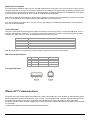
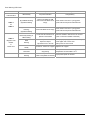
Magnetic Card Reader
A three track Magnetic Card Reader is an option available on the Datamax-O’Neil printers. The MCR reader is designed
to read magnetically encoded data from cards conforming to ANSI/ISO 7810, 7811 standards.
The MC reader converts the F2F encoded signals on the magnetic card, to ISO7811 compatible ASCII format and
transmits the information to the host computer or terminal. Also, the MCR can read one, two or three tracks
simultaneously and bi-directionally.
The table below summarizes the format of the data stored on each magnetic track.
Track 1
ISO1 (IATA)
Track2
ISO2 (ABA)
Recording Density
210 BPI
75 BPI
210 BPI
Recording Capacity
79 characters
40 characters
107 characters
Number of data bits
7
5
7
Track Position
Card Thickness
Read Magnetic Card Data
Track3
ISO3(MINTS)
.76 mm +/- 0.08 mm
ESC M n1 n2 t (CR) or ESC m n1 n2 t (CR)
This command activates the MRC reader and waits until the user swipes a card (or until the timer times out). The
<n1><n2> parameters are used to set the MC reader’s timer. "01" through "99" are valid timer settings. “00” disables
the timer. The ‘t’ value indicates which MCR track number to read.
The printer aborts and transmits the time-out error message if the operator fails to swipe a card within the time period
set by the host application.
If the timer times out, the printer aborts the swipe process, transmits the timeout error message and switches off the
<READING> LED. A good magnetic card swipe automatically terminates the read process. The following table details
the possible combinations for this command:
Magnetic Card Command String
ESC M n1n2 1 CR (CR = Carriage Return) or
ESC m n1n2 1 CR (CR = Carriage Return)
Description
Read Track1 only
ESC M n1n2 2 CR or ESC m n1n2 2 CR
Read Track2 only
ESC M n1n2 3 CR or ESC m n1n2 3 CR
Read Track3 only
ESC M n1n2 4 CR or ESC m n1n2 4 CR
Read Track1 and Track2 simultaneously
ESC M n1n2 5 CR or ESC m n1n2 5 CR
Read Track2 and Track3 simultaneously
ESC M n1n2 6 CR or ESC m n1n2 6 CR
Read Tracks 1,2 and 3 simultaneously
24
Example: The following escape sequence sets the timer to 99 seconds and activates the MRC to read the track #1.
Escape Sequence:
Hexadecimal:
Decimal:
ESC M
1B 4D
27 77
9
39
57
9
39
57
1
31
49
CR
0C
13
ESC m
9
1B 6D 39
27 109 57
9
39
57
1
31
49
CR
0C
13
or
Escape Sequence:
Hexadecimal:
Decimal:
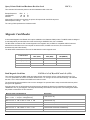
Magnetic Card Data Output Format
The track data retrieved from a magnetic card is transmitted to the host in ISO7811 ASCII format as summarized in the
table below. The first four characters (“%/1/”) flag the track number, the track data follows the flag string terminated with
‘?’-CR-LF.
‘%;+’ are the track start characters, While ‘?’ is the end of track character.
If no data is available for a track then that data field will be empty. If an Error is encountered on any track, a single ‘E’
will be the output for that track’s data field. The ISO 7811 ASCII Format is detailed below:
%/1/
Track1
Data
?CRLF
;/2/
Track 2
Data
?CRLF
+/3/
Track 3
Data
Magnetic Card Read Error Messages
The characters <%> and <E> preface all error messages. Following these two characters is a comma, two ASCII digits
representing the error number (01 through 99), another comma, English description of the error encountered, and finally
a CR-LF which terminates the <Error Message> string. The syntax is as follows:
<%><E>, nn, Error text in ASCII, <CR> <LF>
Where nn is the error number encountered
The printer may transmit three (3) types of Read Error messages. Refer to the table below for detailed description of the
error messages.
Error #
05
07
09
Error Message Transmitted
Time-out Expired
Invalid Track Number
Cancel Request
Interfacing to the Magnetic Card Reader
This section details the software steps required to access the MC reader from a computer or a terminal.
(1) The Host selects the printer by activating the RTS input line or sending wake-up characters to the printer.
(2) The Printer Sends the XON command to the host to indicate that it is ready to receive data from the host.
(3) Once XON is received the host sends an ASCII serial command string to enable the magnetic card reader (e.g. Escm004-cr). The printer switches on the GREEN <READY> LED.
(4) Once the operator swipes the magnetic card, the printer transmits, in ASCII format, the track information found on
the magnetic card.
A good read automatically switches off the MC reader and the <READY> LED.
(5) The <READY> LED illuminates RED if an error is encountered while reading the magnetic card.
The printer transmits a timeout error message if the operator fails to swipe a card in the time period set by the host
application.
25
?CRLF
Cancel Magnetic Card Data Read Command
ESC C
This command cancels the MCR read process. The printer returns to online operation mode.
Escape Sequence:
Hexadecimal:
Decimal:
ESC C
1B 43
27 67
Note that after executing this command the printer will send the message “, 09, Cancel Request” to the host.
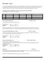
Black Mark Sensing Control Commands
Set Paper-Out Sensitivity
ESC Q Q n CR
This command sets the paper-out sensor sensitivity level. 0 ≤ n ≤ 255.
This command sets the number of 0.125mm dot rows that the printer can advance paper before the sensor detects an
out of paper error. The length of the paper sensitivity must be larger than the length of the black mark on the media to
avoid paper out error.
The value selected for the sensitivity is dependent upon the height of the pre-printed black mark located on the label or
form stock. The default power-on value n is 255 (0xFF).
Example: The following escape sequence sets the paper sensitivity to 6.25mm (50*0.125)
Escape Sequence:
Hexadecimal:
Decimal:
ESC Q
1B 51
27 81
Q
51
81
50
32
50
Enable Black Mark Reporting
ESC Q R CR
This command enables the printer to send reporting messages to the host. Refer to “Black Mark Found” and “Black
Mark not found” commands for details of the messages that are activated.
Escape Sequence:
Hexadecimal:
Decimal:
ESC Q
1B 51
27 81
R
52
82
CR
0D
13
Disable Black Mark Reporting
ESC Q r CR
Prevents the printer from sending report messages to the host. Refer to “Black Mark Found” and “Black Mark not found”
commands for details of the messages that are deactivated
Escape Sequence:
Hexadecimal:
Decimal:
ESC Q
r CR
1B 51 72 0D
27 81 114 13
26
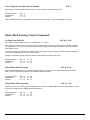
Black Mark Sensing Command Mode
Forward Seek Black Mark
ESC Q F n CR
This command sets the printer to black mark seek mode using a forward feed operation. The value of forward feed is
determined by the user in dot lines (n) where 0 ≤ n ≤ 255 dots. Each dot line corresponds to 0.250mm. If the black
mark is found, the printer responds with the command “Black Mark Found”, otherwise the printer responds with the
command “Black Mark not Found”. Both escape sequence responses are described below.
Example: The following escape sequence advances the paper 80 dot lines looking for a Black Mark.
Escape Sequence:
Hexadecimal:
Decimal:
ESC Q
1B 51
27 81
F
46
70
P
50
80
CR
0D
13
Reverse Seek Black Mark
ESC Q B n CR
This command causes the printer to seek black mark using backward feed until n dot line feeds have been processed;
each dot line feed is 0.25mm.
Not the using this command can cause a paper jam since the paper is advanced in reverse mode. The results may vary
depending on the media used in the printer.
Black Mark Found (Response from printer)
ESC Q ? ? n1, n2
This message is sent to the host and indicates that a black mark has been found. The numbers n1 and n2 are the high
and the low nibble, respectively, describing how many (0.25mm) dot lines were required to find black mark.
Black Mark Not Found (Response from Printer)
ESC Q 0 0 n1 n2
This message is sent to the host and indicates that a black mark has not been found. The numbers n1 and n2 are the
high and the low nibble, respectively, describing how many (0.25mm) dot lines were processed before reporting black
mark not found.
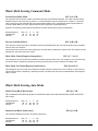
Black Mark Sensing Auto Mode
Enable Front Black Mark Sensor
ESC Q f e CR
This command will enable the printer’s front black mark sensor and automatically disable the BACK
side sensor.
Escape Sequence:
Hexadecimal:
Decimal:
ESC Q
f
e CR
1B 51 66 65 0D
27 81 102 101 13
Disable Front Black Mark Sensor
ESC Q f d CR
This command disables the printer’s front black mark sensor.
Escape Sequence:
Hexadecimal:
Decimal:
ESC Q
f
d CR
1B 51 66 64 0D
27 81 102 100 13
27
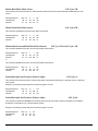
Enable Back Black Mark Sensor
ESC Q b e CR
This command will cause the printer to enable the back black mark sensor and automatically disables the front side
sensor.
Escape Sequence:
Hexadecimal:
Decimal:
ESC Q
1B 51
27 81
b
e CR
62 65 0D
98 101 13
Disable Back Black Mark Sensor
ESC Q b d CR
This command will disable the printer’s back black mark sensor.
Escape Sequence:
Hexadecimal:
Decimal:
ESC Q
1B 51
27 81
b
d CR
62 64 0D
98 100 13
Disable Both Front and Back Black Mark Sensors
ESC Q f x CR or ESC Q b x CR
This command disables the printer’s front and back black mark sensors.
Escape Sequence:
Hexadecimal:
Decimal:
ESC Q
f
x CR
1B 51 66 78 0D
27 81 102 120 13
or
This command disables the printer’s front and back black mark sensors.
Escape Sequence:
Hexadecimal:
Decimal:
ESC Q
b
x CR
1B 51 66 78 0D
27 81 102 120 13
Printed Receipt/Label Presenter Positive Adjust
ESC Q D + n
This command will cause the printer to advance the paper to the distance specified by n dots after a form or label has
been printed.
Example: The following escape sequence will feed the paper 112 dots.
Escape Sequence:
Hexadecimal:
Decimal:
ESC Q
1B 51
27 81
D
44
68
+ 112
2B 70
43 112
Printed Receipt/Label Presenter Positive Adjust
ESC Q P n
This command is identical to Esc Q D + n command and will cause the printer to advance the paper to the distance
specified by n dots after a form or label has been printed.
Example: The following escape sequence will feed the paper 112 dots.
Escape Sequence:
Hexadecimal:
Decimal:
ESC Q
1B 51
27 81
P 112
50 70
80 112
28
Printed Receipt/Label Presenter Negative Adjust (*)
ESC Q D – n
This command will cause the printer to move the paper backwards to a distance specified by n dots after a form or label
has been printed.
Example: The following escape sequence will move the paper backwards 112 dots
Escape Sequence:
Hexadecimal:
Decimal:
ESC Q
1B 51
27 81
D
44
68
- 112
2D 70
45 112
Note: In Auto Q-Mark Mode Form Feed length is limited to the following range: 609 – 3654 print dots. Default value is
set to 1218 dots.
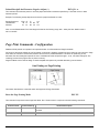
Page Print Commands - Configuration
Datamax-O’Neil printers can operate in two separate modes: Line Print Mode and Page Print Mode.
On Power Up the printer defaults to Line Print Mode. In this mode, all data is printed from top to bottom as it is received. In Page
Print mode, the canvas is constructed in advance and the form is printed afterwards. This allows for positioning of text,
barcodes, lines and rectangles at specific X and Y coordinates and also at specific angles – 0, 90, 180 and 270 degrees. The
rendering process of the page is done in printer’s memory.
Page Print Mode can be used to design a certain template and replace only variable data during communication.
Line Printing vs. Page Printing
This section describes the commands which are supported in Page Print Mode.
Enter the Page Printing Mode
ESC P P
This command is required to enter Page Print Mode. Esc P P also works in conjunction with the following commands:
Command Name
Command String
Enter Buffer Mode
Esc P $
Exit Buffer Mode
Print Buffer Content
Esc P #
^D
Command Description
Printer Enters Buffer Mode. All data is retained in the Buffer until ^ D ( 0x04) is
received.
Exits Buffer Mode and puts the printer into the Line print Mode
Prints Buffer Content; Printer is ready to receive more data.
29
Mark Beginning of a Page
BeginPage();
This command follows Esc P P command and is used to indicate the beginning of a form in page printing mode.
Define the Page Size
SetPageSize (width, height);
This command is used to define the valid drawing area for a label or form. Two parameters are required: width and height of the
form, measured in dots.
Set Margins
SetMargin (lm, tm);
This command sets the left margin to lm and the top margin to tm. The margin is then used as a start point (0, 0) for the form or
label.
Mark Page End, Print and Exit
EndPage();
This command is used to end a form or label while in the Page Printing mode. This command also forces the printer to print a
label or form.
Page Print Commands – Draw Commands
Draw Text
DrawText (x,y,color,angle,"string");
Draws text at any coordinate on the canvas.
DrawText “data” prints the text enclosed in the double quotes at the current cursor location. x and y specify where the text is to
be printed (upper left corner of the first letter of the top line).
Parameters:
x
specifies “x” axis location
y
specifies “y” axis location
Color
Angle
specifies text color: 0 = white, 1= black.
User may print white text on an existing black background by specifying color = 0.
specifies text direction
Angle
String
Print angle
Description
0
0 degrees Counter-clockwise
Prints text horizontally from left to right.
1
90 degrees Counter-clockwise
Prints text vertically in the upward direction
2
180 degrees Counter-clockwise
Prints text horizontally from right to left
3
270 degrees Counter-clockwise
Prints text vertically in the downward direction.
specifies the text to print
Multiple lines can be printed with a single ‘DrawText’ command by separating the lines with \n characters. Text formatting is
accomplished by tags inserted in the string argument. The formatting is effective only in the string in which it appears and does
not carry over to the subsequent DrawText commands. The text formatting commands are listed below.
30
Command
<b>, </b>
<u>, </u>
<h = value>
<w = value>
<f = value>
\n
\<, \>, \”, \\
Name
Bold
Underline
Text Height
Text Width
Font
New Line
Literals
Description
Text enclosed by <b> and </b> appear in bold.
Text enclosed by <u> and </u> are underlined.
Text height is magnified by the given numeric value. Use <h = 1> to return to original size.
Text width is magnified by the given numeric value. Use <w = 1> to return to original size.
Sets the font. value = {0 .. 9}.
Moves the cursor to the beginning of the next line.
Use backslashes to print these special characters.
Example: The figure below shows the use of the “\n” command as well as the effect of the angle command in the text being
printed with the DrawText command
Draw Rectangle
DrawRectangle (x1, y1, x2, y2,color,width);
Draws a rectangle object at any coordinate on the canvas.
DrawRectangle command draws either a hollow or a filled rectangle. (x1, y1) and (x2, y2) specify the two diagonally opposing
corners. All measurements are in dots.
Parameters:
x1, y1
Top left corner coordinates (x1, y1)
x2, y2
Bottom right corner coordinates (x2, y2)
color
Specifies the line or fill color: 0 = white, 1 = black
The user may draw a white rectangle on a black background only by specifying color
parameter = 0.
width
Specifies the line width of a hollow rectangle. A zero-width results in a filled rectangle
Draw Bar Code
DrawBarcode(x,y,angle,annotate,type,height, "data");
Draws a barcode object at any coordinate on the canvas.
Parameters:
X
Indicates location on “x” axis of the left top corner
Y
indicates location on “y” axis of the left top corner
angle
annotate
type
Values 0, 1, 2, or 3 allow the barcode to be rotated 0, 90, 180, or 270 degrees respectively
Setting annotate to 1 allows human-readable text to appear. ‘0’ disables this function.
Indicates the barcode type to be printed. The barcodes supported are listed below:
31
Type Value
1
2
3
4
5
height
Barcode
type
Code 39
Code 128
Code 2 of 5
UPC
Codabar
Sets the height of barcode in units of dots
data
Specifies the content of the barcode. It is the user’s responsibility to supply data that is appropriate for the
chosen code. For example, Code 39 will not accept lower case letters. Refer to the Barcode Specification section for detailed
information of characters accepted by each barcode
Example: The following commands are used to create code 39 barcode inside an outline box.
P$PP
BeginPage();
SetMargin(0,0);
SetPageSize(576,2496);
DrawRectangle(61,35,524,265,1,3);
DrawText(119,75,1,0,"<f=1>DEMO Page Printing Mode");
DrawBarcode(129,130,0,1,1,70,"CODE39");
EndPage();
P#
The printer also allows for Page Print mode and Line Print mode printing on the same page.
Example: Print text and barcode in Page Print Mode (without entering and exiting Buffer Mode) accompanied by text in
Line Print Mode.
PP
BeginPage();
SetMargin(0,0);
SetPageSize(576,150);
DrawBarcode(71,60,0,1,1,25,"ABC123");
DrawText(7,10,1,0,"Test: Welcome to Page Print Mode");
DrawText(10,35,1,0,"This barcode 39 is printed in Page
Print Mode");
DrawText(10,110,1,0,"Exiting Page Print Mode");
EndPage();
Welcome to Line Print Mode
This text line is printed in Line Print Mode.
You are now out of Page Print Mode!!!
32
Form FiestaTM
Form Fiesta is a Form and Label Generating Software that can be used to automate the label design process. It is provided to
Datamax-O’Neil partners and customers at no charge. All supported commands are implemented in Form Fiesta and are
automatically generated when an element is drawn onto the canvas on the screen. Developers can use Form Fiesta to generate
a label and then copy the commands generated in the yellow section of the screen (these are the commands which render the
image on the screen). The variable data can be acquired by the user’s application and replaced in the command string.
Example: The code below demonstrates how to implement this using a simple VB program. ‘CustomerName’ and ‘csCarModel’
are two variables which are substituted in the string.
Private Sub Command1_Click()
csTicket = Chr$(27) + "P$" + Chr$(27) + "PP" + vbCrLf + "BeginPage();" + vbCrLf
csTicket = csTicket + "SetPageSize(400,200);" + vbCrLf
csTicket = csTicket + "DrawRectangle(30,0,330,40,1,0);" + vbCrLf
csTicket = csTicket + "DrawText(80,10,0,0,""<f=6><b>Dollar Rental"");" + vbCrLf
csTicket = csTicket + "DrawText(30,60,1,0,""Customer"");" + vbCrLf
csTicket = csTicket + "DrawRectangle(140,50,330,90,1,3);" + vbCrLf
csTicket = csTicket + "DrawText(150,60,1,0,""" + CustomerName + """);" + vbCrLf
csTicket = csTicket + "DrawText(30,110,1,0,""Model"");" + vbCrLf
csTicket = csTicket + "DrawRectangle(140,100,330,140,1,3);" + vbCrLf
If Option1.Item(0) Then csCarModel = "Taurus"
If Option1.Item(1) Then csCarModel = "Cavalier"
If Option1.Item(2) Then csCarModel = "Neon"
csTicket = csTicket + "DrawText(150,110,1,0,""" + csCarModel + """);" + vbCrLf
csTicket = csTicket + "EndPage()" +vbCrLf+Chr$(27)+"P#" + vbCr+Chr$(4)+vbCrLf
Ticket.TicketText = csTicket
Ticket.Visible = True
MSComm1.CommPort = 1
MSComm1.PortOpen = True
MSComm1.Output = csTicket + vbCrLf
MSComm1.PortOpen = False
End Sub
The Form Fiesta installation program, as well as instructions for using the software, is available in the Developer’s CD.
33
Download - Printer Default Setup
Select Setup Download mode
ESC D S
This command puts the printer into the Download mode. The printer will response with a ’?’ character.
Escape Sequence:
Hexadecimal:
Decimal:
ESC D
1B 44
27 68
S
53
83
Start Default download process
ESC S L
This command alerts the printer that a file will now be downloaded.
Escape Sequence:
Hexadecimal:
Decimal:
ESC S
1B 53
27 83
L
4C
76
Stop Download Process
ESC S T 0xFF CR
This command stops the downloading process.
Escape Sequence:
Hexadecimal:
Decimal:
ESC S
1B 53
27 83
T 0xFF CR
54 255 0D
84 255 13
Store In Flash Default setup data
ESC S B CR
This command allows the printer to burn the command file in Flash memory. After finishing the process, the printer will
respond with the”D! X” characters.
Escape Sequence:
Hexadecimal:
Decimal:
ESC S
1B 53
27 83
B
42
66
CR
0D
13
Example: The following escape commands will change the default font to “k2” (48 characters per line). The “k2” font will
be restored in place of the k3 value every time the printer is power cycle
The commands below must be sent sequentially:
Escape sequence 1:
Escape sequence 2:
Escape sequence 3:
ESC D
ESC S
ESC k
S
L
2
(The previous command can be a binary file with a list of commands to initiate default start up)
Escape sequence 4:
Escape sequence 5:
ESC
ESC
S
S
T 0xFF CR
B CR
34
Download – Self test Message Hardware Information
Select Setup Download mode
ESC D S
This command puts the printer into the Download mode. The printer will response with a ’?’ character.
Escape Sequence:
Hexadecimal:
Decimal:
ESC D
1B 44
27 68
S
53
83
Start Hardware Information download process
ESC S I
This command alerts the printer that a file will now be downloaded.
Escape Sequence:
Hexadecimal:
Decimal:
ESC S
1B 53
27 83
I
49
73
Stop Download Process
ESC S T 0xFF CR
This command stops the downloading process.
Escape Sequence:
Hexadecimal:
Decimal:
ESC S
1B 53
27 83
T 0xFF CR
54 FF 0D
84 255 13
Store In Flash Default setup data
ESC S B CR
This command allows the printer to burn the command file in Flash memory. After finishing the process, the printer will
respond with the ”D!X” characters.
Escape Sequence:
Hexadecimal:
Decimal:
ESC S
1B 53
27 83
B
42
66
CR
0D
13
Print Hardware Information
ESC L g 8
This command prints a hardware information message previously store in memory.
Escape Sequence:
Hexadecimal:
Decimal:
ESC L
g
8
1B 4C 67 38
27 76 103 56
Example: The following escape commands will burn “Hardware Information” string into the flash memory. The “Hardware
Information” string will be printed below battery voltage readings in the self test message.
The commands below must be sent sequentially:
Escape sequence 1:
Escape sequence 2:
Escape sequence 3:
ESC D
S
ESC S
I
Hardware Information
Escape sequence 4:
Escape sequence 5:
ESC
ESC
S
S
T 0xFF CR
B CR
35
Download – Logo
The Graphic Logo feature allows the storage of a formatted Bitmap file in nonvolatile memory. Up to eight memory sectors, of up
to 64,000 bytes each, are reserved to store a Graphic Logo in the printer. Upon receipt of a Graphic Logo print command, the
Graphic Logo data is sent to the printer. This feature allows printing of a stored graphic image as part of a receipt.
Logo images must be modified and saved to a .prn file prior to logo download.
The specifications for the logo memory are as follows:
Printer
Number of Logos
Bytes per logo
Dot lines per logo
Dots per line
Logo Locations Available
2 inch
8 (FLASH) 0 ≤ n ≤ 7
64,000
1365
384
0-7
3 inch
8 (FLASH) 0 ≤ n ≤ 7
64,000
910
576
0-7
4 inch
8 (FLASH) 0 ≤ n ≤ 7
64,000
630
832
0-3
Select Logo Download mode
ESC D L CR LF
This command places the printer in Flash Logo mode.
Escape Sequence:
Hexadecimal:
Decimal:
ESC D
1B 44
27 68
L
4C
76
CR
0D
13
LF
0A
10
Before executing this command, the printer power must be cycled, alternatively the command ESC X X can be sent.
The printer responds by sending a ‘?’ character to the host application indicating that the Flash Logo Mode is enabled.
Select logo Download Memory Location
ESC L G n CR LF
This command selects the memory location in which to store the logo. The parameter n can take values between 0 – 7
(n varies with printer model. Please refer to the above table).
Escape Sequence:
Hexadecimal:
Decimal:
ESC L
1B 4C
27 76
G
47
71
1
31
49
CR
0D
13
LF
0A
10
Stop Logo Download Process
ESC L G 0xFF CR LF
This command terminates the logo uploading process.
The printer saves the received Logo data in Flash and sends D!X characters to the host, indicating that the logo data
was saved successfully.
Escape Sequence:
ESC L
G 0xFF CR LF
Hexadecimal:
1B 4C 47 0xFF 0D 0A
Decimal:
27 76 71 255 13 10
Print Logo
ESC L g n
This command prints a logo previously store in memory. The parameter n instructs the printer to print the graphic stored
in memory locations (refer to table above for logo location availability)
Example 1: The following escape sequence will print the logo at memory location one.
36
Escape Sequence:
Hexadecimal:
Decimal:
ESC L
g
1
1B 4C 67 31
27 76 103 49
Example 2: The following example replaces logo location 1 with the logo image contained in logo.prn file.
The following escape commands must be sent sequentially and are necessary to complete logo download.
Escape sequence 1:
Escape sequence 2:
ESC D
ESC L
L
G
CR LF
1 CR
LF
Escape sequence 3:logo.prn file
Escape sequence 4:
Escape sequence 5:
ESC
ESC
L
L
G 0xFF CR
g
1
LF
The following table represents the LED behavior for each Escape sequence during logo download.
Command
Description
Printer Response
ESC D L CR LF
Select Logo Download Mode
ESC L G n CR LF
Send Graphic Logo File
ESC L G 0xFF CR LF
Select Memory Location
Send a Binary file with the Logo
image
Stop Loading Graphic Logo
ESC L g n
Print Graphic Logo
?
none
none
D!X
Printer Prints Logo n
LED Status
Power LED - Flashing Green
MRC & Error – Steady Red
Power LED - Flashing green
Power LED - Flashing green
While the logo is being burned
Power LED – Steady Green
MRC & Error – Steady Red
When Burning complete
Power LED – Steady Green
none
Note: The above logo download commands are intended for Developers only. Please contact Customer Support for any
Logo Download Utilities.
Download – Fonts
Enable Font Downloading
ESC D F CR
This command will enable the font download feature.
Escape Sequence:
Hexadecimal:
Decimal:
ESC D
1B 44
27 68
F
46
70
CR
0D
13
Display Tables Information
ESC F I CR
This command will instruct the printer to display the font table’s information at the host. The printer must be connected
to the host in order to receive the font table’s information.
Escape Sequence:
Hexadecimal:
Decimal:
ESC F I CR
1B 46 49 0D
27 70 73 13
Command is valid after ESC, D, F, CR
37
Display Tables Information
ESC D I CR
Same description as the command directly above. This command is for Legacy printer’s compatibility.
Escape Sequence:
Hexadecimal:
Decimal:
ESC D
1B 44
27 68
I
49
73
CR
0D
13
Disable Font Download Mode
ESC F X
This command will disable the font download mode and put the printer in ready print mode.
Escape Sequence:
Hexadecimal:
Decimal:
ESC F
1B 46
27 70
X
58
88
Display Font Download Current Settings
ESC F S m t k f CR
This command will instruct the printer to display the current font download settings. The printer will send the following
string to the host:
Esc-‘F’-‘S’ m t k f
Parameters
m
‘0’=standard response, ‘1’ =response with diagnostics message (default)
t
Font File type. t = ‘0’. BDF formatted file (default). t= ‘1’ through ‘9’ reserved
k
Font Table: column value. = ‘0’ through ‘9’
f
Font Table: row value. f = ‘0’ through ‘9’
Set Font Download Parameter
ESC F P m t k f CR
This command sets the font download parameters such as for the row and column of the font memory table. The
command structure is detailed below.
Parameters
m
t
k
f
‘0’=standard response, ‘1’ =response with diagnostics message (default)
Font File Type. t = ‘0’. BDF formatted file (default). t= ‘1’ through ‘9’ reserved
Font Table: column value. = ‘0’ through ‘9’
Font Table: row value. f = ‘0’ through ‘9’
38
Select Load Operating Mode
ESC F M m CR
This command selects the load operating mode. Possible values for parameter m are ‘0’: Standard response or ‘1’ :
Response with diagnostics message (default).
Command
String
Command
Description
Printer Response
m =1
Printer Response
m =0
Esc-‘D’-‘F’
Enable font
downloading
?
?
Display tables
Information
Display installed
Esc-‘F’-‘I’
LED Status
Communication LED – Flashing Green
MCR/Printer Error LED –Steady Red
Font tables info
(refer to Table 5)
‘1’: if command correct
‘0’: otherwise
Communication LED – Flashing Green
‘1’: if command correct
‘0’: otherwise
Communication LED – Flashing Green
‘1’: if command correct
‘0’: otherwise
Communication LED – Flashing Green
‘1’: if command correct
‘0’: otherwise
Communication LED – Flashing Green
MCR/Printer Error LED –Steady Red
Esc-‘F’-‘S’<CR> or <LF>
Display font
download current
Settings
Esc-‘F’-‘S’ m t k f
Esc-‘F’-‘P’ – m t - k - f - <CR>
or <LF>
Set Font
Download
Parameter
Esc-‘F’-‘S’ m t k f
Esc-‘F’-‘M’- m <CR> or <LF>
To select Mode
Esc-‘F’-‘S’ m t k f
Esc-‘F’-‘K’- k <CR> or <LF>
To select font
column(K) value
Esc-‘F’-‘S’-m t k f
‘1’: if command correct
‘0’: otherwise
Communication LED - Flashing green
Esc-‘F’-‘F’- f <CR> or <LF>
To select font
row(F) value
Esc-‘F’-‘S’ m t k f
‘1’: if command correct
‘0’: otherwise
Communication LED - Flashing green
Esc-‘F’-‘L’ – t <CR> or <LF>
Select file type
**and start of font
download
Esc-‘F’-‘S’ m t k f
‘1’: if command correct
‘0’: otherwise
Communication LED - Flashing green
Send the .bdf file
Send the File
MCR/Printer Error LED –Steady Red
MCR/Printer Error LED –Steady Red
MCR/Printer Error LED –Steady Red
While File is transferring:
Communication LED - Flashing Green
When transfer is complete:
Communication LED - Flashing Green
Total number of characters transferred is
displayed
On burn process
Esc-‘F’- ‘B’
<CR> or <LF>
To program or
burn font on flash
On burn process
Complete:
Complete:
D!X
D!X
While the font is being burned in
FLASH
Communication LED – Flashing Green
MCR/Printer Error LED - Flashing Red
When Burning complete
Communication LED – Steady Green
39
Select Font Row
ESC F F f CR
This command selects the row value for the font tables. The parameter f can be set in the range of ‘0’ to ‘9’
Select Font Column
ESC F K k CR
This command selects the column value for the font tables. The parameter k can be set in the range of ‘0’ to ‘9’
Select File Type
ESC F L t CR
This command selects the file type to be uploaded. The parameter t has a range of values between ‘0’ to ‘9’. The default
value is ‘0’ which means “BDF” format.
Save Font File in Flash
ESC F B CR
This command instructs the printer to program or burn font onto Flash memory.
The table below summarizes the font downloading commands supported by the Datamax-O’Neil printer along with the
printer’s expected LED status.
Escape Sequence:
Hexadecimal:
Decimal:
ESC F
1B 46
27 70
B
42
66
CR
0D
13
Important Font Downloading Notes:
The file to be downloaded must be .BDF formatted.
When downloading, ensure that the metrics of the fonts to be downloaded are equal or smaller than the metrics of the
existing font in the location in question; otherwise the fonts will not be downloaded correctly.
The escape sequence ESC D F CR must be the first command after power up, otherwise the printer will print the
command instead of executing it. You can also use the commands ESC X X CR command to initialize the printer after
other escape commands have been used.
Once a font has been downloaded, press the FEED button twice to exit the downloading mode. Shut the printer OFF by
pressing the ON/OFF switch.
Each character’s header uses .DBF font and represents the true size of the font bitmap.
Example1: For a 16x23 font, the header at the beginning of each character must appear as follows:
BBX 16 23 0 0
Example 2: For a 10 x 23 font, the header at the beginning of each character must appear as:
BBX 10 23 0 0
If the font to be downloaded is one byte in size (8 x 23), the .BDF file must be one byte only in size. Otherwise the
firmware will not accept the font!
40
Example 1: BBX 08 23 0 0
BITMAP
0008
000F
0002
0003
INCORRECT
Example 2: BBX 08 23 0 0
BITMAP
08
0F
02
03
CORRECT
The name of the font is indicated at the beginning of the .BDF file, therefore: FONT Font12C.BDF. If only the file is
renamed, the firmware will not recognize it; in this case, the .BDF file must be opened and the file name must be
changed as in the format shown previously in this paragraph.
The following section shows the steps required to upload a new font into the printer memory.
1)
Have the .BDF font file available and ready. The file should contain all of the characters which are to be downloaded. When
downloading, ensure that the Serial Port setting for the Terminal Program is configured for Hardware Handshaking. If the file
is in .ASM format rather than a .BDF format, use Datamax-O’Neil’s ‘asm2bdf’ utility to convert the file to .BDF format.
Instructions on how to use the utility are available in the USING THE ASM2BDF UTILITY document available in the FONT
section of the supplied Developer’s CD.
2)
Cycle Printer Power or Send ESC X X command
3)
Send Esc D F and wait for a question mark to return from the printer. The Ready and Status LED should each illuminate in
green.
4)
Send Esc F I to view the current font table information
5)
Send Esc F K 1 <CR> or <LF> – This will select the second column of the table – the Power LED will begin flashing Green
and the Status LED will illuminate a steady RED.
6)
Send Esc F F 1 <CR>or <LF> – This will select the second row of the table - the Power LED will start flashing Green and
the Status LED will turn steady RED.
7)
Send Esc F L 0 <CR>or <LF> which will signal that the file you are sending is .DBF format (this command is implemented
primarily for future releases when users will be able to download more than one font format) - the Power LED will start
flashing Green and the Status LED will illuminate a steady RED.
8)
Send the .BDF file - While the File is transferring the Power LED is steady Green and the Status LED is steady RED – when
the transfer is complete the Status LED switches OFF and the Power LED flashes Green. The .BDF font metrics must be
equal or smaller than the metrics of the existing font.
9) Send Esc F B <CR>or <LF> - The Power (green) and Status (red) LEDs are steady while the font is burned in FLASH.
When burning has been completed, both the Power LED (green) and the Status LED (red) begin flashing.
10) The .BDF font in the example above has been stored in the International Section of the Courier Mode 1 font (F = 1, k = 1).
Unplug the Serial Cable, press the Feed button, and shut the printer OFF by pressing the ON/OFF button.
41
Bluetooth™ & WiFi Setup Command
Datamax-O’Neil printers can be placed in pass-thru mode. In pass-thru mode, data communication will only occur between the
two selected UARTS. This mode of operation is used to setup the Bluetooth™ or 802.11b/g interface parameters. While in this
mode, printing is disabled.
Select Pass-Thru Command Mode
ESC P U n1 U n2 T t0 t1 t2 (CR)
This command sets the printer in pass-thru mode. In most serial applications the command can be sent manually or as a file. For
UART selection only use ECU application.
Parameter
Description
n1
Source UART, values 0 – 4
UART0 = Serial Interface
UART1 = Wireless Interface (BT, WiFi)
UART2 = Wireless Interface (BT, WiFi)
UART3 = IrDA Interface
UART4 = USB Interface
Destination UART, values 0 – 4
UART0 = Serial Interface
UART1 = Wireless Interface (BT, WiFi)
UART2 = Wireless Interface (BT, WiFi)
UART3 = IrDA Interface
UART4 = USB Interface
Pass-thru timeout, value 0 – 9
Pass-thru timeout, value 0 – 9
Pass-thru timeout, value 0 – 9
n2
t0
t1
t2
Note: Pass-thru timeout value 000 is not a valid entry
Example 1: The Pass-thru sequence below is used to put Apex2 printer is Pass-thru mode from serial to Wireless with timeout
value set to 999 seconds.
Escape Sequence:
Hexadecimal:
Decimal:
ESC P
1B 50
27 80
U
55
85
0
00
0
U
55
85
2
32
50
T
54
84
9
09
9
9
09
9
9
09
9
CR
0D
13
Example 2: The Pass-thru sequence below is used to put Apex3 printer is Pass-thru mode from serial to Wireless with timeout
value set to 999 seconds.
Escape Sequence:
Hexadecimal:
Decimal:
ESC P
1B 50
27 80
U
5
85
0
00
0
U
55
85
1
31
49
T
54
84
9
09
9
9
09
9
9
09
9
CR
0D
13
Example 3: The Pass-thru sequence below is used to put Apex4 printer is Pass-thru mode from USB to Wireless with timeout
value set to 999 seconds.
Escape Sequence:
Hexadecimal:
Decimal:
ESC U
1B 50
27 80
4
55
85
U
55
85
2
32
50
T
54
84
9
09
9
9
09
9
9
09
9
CR
0D
13
Note: Pass-thru command is not available when Source (n1) = Destination (n2)
The Pass-thru mode terminates under three conditions:
After pressing the FEED button
After TIMEOUT duration specified in the pass-thru command has EXPIRED
After receiving three consecutive “#” characters.
42
Emulation
The printer’s default mode of operation of Datamax-O’Neil Printers is the Datamax-O’Neil Printer Command Language (ExPCL).
The emulations offered by Datamax-O’Neil Printers allow compatibility with printing systems and software created for printers
offered by other mobile printer’s manufacturers. The Datamax-O’Neil printers offer the following emulations:
O’Neil: Line Print Mode and Easy Print Mode
Zebra: CPCL Line Print Mode.
To select a temporary emulation mode the user must use the following command:
Select Emulation
ESC E n
This command selects emulation mode n by which future commands will be interpreted as described in the following table. The
selected mode will be in effect until another Select Emulation command is received or the printer is manually reset by cycling
power on the printer.
Once the emulation has been selected, please refer to the section of this manual that describes the commands
available for that emulation.
Example: The following escape sequence will set the printer to O’Neil Emulation.
Escape Sequence:
ESC E
O
Hexadecimal:
1B 45 4F
Decimal:
27 69 79
n
N
O
Z
C
Emulation Language
Datamax-O’Neil Printer Command Language
O’Neil Emulation Line Print Mode
O’Neil Emulation EZ Print Mode
CPCL Emulation
The following table details the behavior of the printer to enter and exit the emulation mode.
Getting From ( Mode Name)
Regular Mode ( Datamax-O’Neil )
O’Neil Easy Print Mode
O’Neil Line Print Mode
Regular Mode(Datamax-O’Neil)
ESC E N
ESC E N
Line Print Mode
Esc E O
{LP}
Easy Print Mode
ESC E Z
ESC E Z
Note: O’Neil EZ Print Mode and CPCL emulation are not supported in version 1.0.1
O’Neil Line Print mode
O’Neil Printers can operate in one of two modes: Easy Print mode and Line Print Mode. Only two commands are implemented in the
Easy Print mode – {LP} which is the command which brings the printer from Easy Print Mode to Line Print Mode and the other
command is ESC E N (N for Normal Datamax-O’Neil Mode) which brings the Datamax-O’Neil printer out of the Emulation into its
regular Datamax-O’Neil command mode.
The table below details the list of supported commands of the O’Neil Line Print Mode emulation.
43
Esc C n
This command is ignored by the Datamax-O’Neil printer. It is recognized but no action is taken
Esc A n
This command sets the number of blank dot lines that are fed between character lines. “n” is
the number of interline spacing
Originally n = (0x01..0x9B) in our version however n = (0x01..0x0A).
CAN (^X)
Esc V n1 n2
104*number of lines bytes of data
Esc B/Esc E
Cancels the unprinted characters on the forming line.
Prints the next (n1*256 + n2) dot-lines as bit mapped graphics. The numbers n1n2 form a 16
bit set with the MSB first. The printer will remain in Graphic mode until the full number of bytes
has been received.
Accepts compressed graphics data
SO (^N)
Set double wide print – with Datamax-O’Neil double wide does not mean burn the dot twice
but rather increase the space between the characters
SI (^O)
Condensed printing – go back to normal mode
FF (^L)
Feeds 10 lines and the information in the buffer
LF (^J)
Line feed
CR (^M)
Carriage Return
Font Select – the Datamax-O’Neil Fonts are matched as close as possible to the Line Print
fonts n (0x20..0x26)
Esc w 20 - 16w x 23h Font
Esc w 21 – 10w x 23h Font
Esc w 22 – 16w x 23h Font
Esc w 23 – 16w x 46h Font
Esc w 24 - 12w x 23h Font
Esc w 25 - 9w x 23h Font
Esc w 26 - 16w x 23h Font
Esc w n
Esc H n
Esc Q n1n2
Doubles the height – no matter what the n value is
Advance n1n2 from Q mark – Datamax-O’Neil Printer can advance only up to 255 graphic
lines from the Q Mark and the Q mark has to be within 255 lines from the beginning point.
Esc R n
This command switches between the two Character Tables in the Datamax-O’Neil Printer –
International Character Table and Line Drawn Character Table.
Esc ! n
Set double high and double wide n = 16d (0x10) – double high
n = 32d (0x20)– double wide
n = 48d (0x30)– double high and wide
Esc @
Reset the printer to defaults
Note: This command does not clear the print buffer! Use the Cancel (CAN) command to clear
the buffer.
This command will not restore any changes that were burned into the flash memory such as:
fonts, logos, default power up message or hardware information message.
Esc EZ
{LP}
Go to Easy Print Mode
From EZ Print mode go to Line Print Mode
44
Communications Settings
Dip Switch Settings
The Datamax-O’Neil printers support Serial RS232, IrDA compatible infrared communication interfaces and
USB*1.Bluetooth™ and Wi-Fi communication are also available as an optional feature. Serial/USB IrDA, Wi-Fi and
Bluetooth™ communication settings can be changed via a DIP switch located on the control card. In the following
sections each setting is discussed in more detail.
Function (APEX2,3,4)
Communication Interface
RS232
1
Switch #
SW 1
SW 2
OFF
OFF
SW 3
SW 4
SW 5
Notes
SW 6
SW 7
Baud rate set by Dip switches 3,4
and 5
Baud Rate can be negotiated up to
the value specified through Dip
switches 3,4 and 5
IrDA
ON
OFF
Bluetooth or 802.11g
OFF
ON
N/A
ON
ON
USB
X
X
OFF
OFF
ON
USB Bootloader
X
X
ON
OFF
ON
2
3
4
SW 8
Setting not supported
Baud Rate
SW 3
SW 4
SW 5
115200
OFF
OFF
OFF
57600
ON
OFF
OFF
38400
OFF
ON
OFF
19200
ON
ON
OFF
14400
OFF
OFF
ON
9600
ON
OFF
ON
2400
OFF
ON
ON
1200
ON
ON
ON
RS232 and IrDA only
Use for fixed IrDA
Parity Bit
SW 6
SW 7
Parity Enabled (ODD)
ON
ON
Does not apply for IrDA
Parity Enabled (EVEN)
ON
OFF
Does not apply for IrDA
Auto Power Save
SW 8
Power Save Enabled
ON
Auto Power Down
Power Save Disabled
OFF
Manual On/Off
1
If IrDA is not installed, printer will default to RS232 mode with baud rate 115200
X stands for Don’t Care: Dip Switch 7 will override 1 and 2
3
Firmware Applies to Apex 4 - Version 1.10 or later, Check availability for other printer models
4
Baud Rate and Parity are applicable to RS232 and IrDA communication mode ONLY
2
45
Serial Communication (RS232C)
The RS232C Interface signals for the Datamax-O’Neil printers are terminated on a 6 PIN RJ type data connector
located on the side of the printer. Six connections are provided from the Serial Interface to the host computer. A
minimum of two connections are required for operation, RXD – pin 3 and Common – pin 1.The proper baud rate and
protocol settings are required to communicate with the host device. The printer defaults to 115.2 K BAUD, 8 DATA
BITS, NO PARITY BIT, and two STOP BITs on initial power up. Two communication handshaking protocols are
supported by the Datamax-O’Neil printers, Serial Busy protocol and XON/XOFF protocols.
Serial Busy Protocol
For the serial busy handshaking mode, request to send printer input (RTS) and clear to send printer output (CTS) are
used to control data flow to and from the printer.
The RTS and CTS are considered to be valid or active when the signal level is positive (3 to 12VDC). A positive RTS
signal from the host device enables the printer. The RTS signal is monitored during data transmission from the printer to
the host device, the printer transmits data to the host device only if RTS input is high. The printer raises CTS output
when it is ready to accept data. The printer lowers CTS line when the print buffer has less than 256 unused locations.
XON/XOFF Protocol
For the XON/XOFF handshaking mode, the printer transmits XON (0x11) when it is ready to accept data, and XOFF
(0x13) when the print buffer has fewer than 256 unused locations. Under XON/XOFF protocol, the data flow from the
printer's serial port is halted on receipt of an XOFF from the Host device and resumed on receipt of a XON.
RS232C Connections
The RS232C Interface signals for the Datamax-O’Neil printers are terminated on a 6 PIN RJ25 type data connector
located at the back of the printer.
Six connections are provided from the Serial Interface to the host computer. The table below lists the Serial Interface
signals and pin-outs for the RJ25 connector while pin locations are shown in Figure below.
A minimum of two signal connections are required for operation, RXD - pin3 and Common - pin1.
RJ25 Connector PIN #
Functional Description
Signal Name
3
RS232 from Host (INPUT)
RXD
2
RS232 from Printer (OUTPUT)
TXD
6
Request to send from Host (INPUT)
RTS
4
Clear to send from Printer (OUTPUT)
CTS
Logic common
COM
1, 5
46
RS232C Technical Specifications
Name
Value
Data Transfer Rate
1200 – 115200 Baud
Word Length
10 or 11 bits
Start Bit
1
Data Bits
8
Parity Bit
None, Odd or Even
Stop Bits
Auto Select 1 or 2
Signal Levels
RS232C
Mark or Logical 1
-3 to -15 VDC
Space or Logical 0
+ 3 to + 15 VDC
Handshaking
Two modes are supported (Software and Hardware)
Hardware
RTS/CTS
Software
XON/XOFF
Auto Power Up
Positive Signal on RTS input switches the printer ON
USB Communication (USB)
Overview
Apex printer comes equipped with a USB 2.0 slave port. Everything that can be done through the RS-232 port can now
be done through the USB port, using A to B type USB cable. You may print to or send commands to the printer from a
PC or any equipment that can act as a USB master.
Dip switch setting
To enable USB, you must set the dipswitches on the printer as below:
SW 1
Any
position
SW 2
Any
position
SW 3
Any
position
SW 4
Any
position
SW 5
Any
position
SW 6
Off
SW 7
On
SW 8
Any
position
Compatible Software
The host and printer communicate through a method called the "Virtual Com Port", in which a software intermediary called the
"driver" makes the USB connection look like a com port to the end-application. Consequently, all software that communicates
through the com port is compatible. You may continue to use legacy software, such as the TeraTerm terminal emulation
software.
47
Software Driver Installation
You must install the USB driver before you can use USB communication on the printer. Turn on the printer and connect it to the
PC with a USB cable. If the driver has never been installed before, a dialog box will appear. Reply by selecting "Install from a list
or specific location" and indicating the location of the file usbprintercdc.inf supplied with the CD. The usbprintercdc.inf file points
to the actual driver called msports.dll, which is a part of the Windows operating system.
Next, open the Windows Device Manager. (Control Panel > System > Hardware Tab > Device Manager) Under the Ports (COM
& LPT), you should see an entry named "Datamax-O’Neil USB CDC Communications Port”
If you ever needed to uninstall the driver, you may do so by right-clicking on the "Datamax-O’Neil USB CDC Communications
Port” from the Device Manager.
TeraTerm Example
TeraTerm is a free terminal emulator program. Make sure TeraTerm is not running when you connect the USB cable. Then run
TeraTerm, select (Setup > Serial Port...) to configure it and save the configuration. There are only three items that you need to
configure: Port, Data, and Flow control. All other parameters can be set to any value.
PORT
Data
Baud rate
Parity
Stop
Flow control
COM<n> where <n> is the port number where USB driver was installed
8 bit
Any value
Any value
Any value
None
Note: Select ENTER key on the keyboard to advance paper in the printer and to verify communication.
USB Technical Specifications
Pin
1
2
3
4
Name
VCC
DD+
GND
Cable Color
Red
White
Green
Black
Description
+5V
Data Data +
Ground
A to B type USB cable
Bluetooth™ Communications
The printer control card communicates with the Bluetooth™ base band interface at 115.2 K Baud/sec for serial interface printers
and 57.6 K Baud/sec for USB interface printers, using no parity. To select the Bluetooth™ interface, Dip Switch # 2 must be ON
and all other Dip Switches must be OFF. If required by the host application to enter 0 (digit zero) for PIN number while
connecting to the BT module. Bluetooth settings can be changed via the AT command set (Refer to Developer’s CD for available
AT commands).
The table below details the Bluetooth Datamax-O’Neil default settings:
48
Settings
Value
Name
APEX#, where # matches the printer model
Serial Settings
115200,8,n,2,n
USB Settings
57600, 8, n, 2, n
Discoverability mode
Generally Discoverable
Connectivity mode
GAP Connectable
Security mode
Security Disabled
Fixed PIN
0 (Zero)
Set Master/Slave Policy
Always let the connecting device select the master/slave role on incoming connections
Client Profile
Disable Client Services
Server Profile
Serial Port Profile Server enabled
Wireless Multi-drop mode
disabled, forward to host only
Set Serial Interface
RS232
Configuration over Bluetooth
Enabled
Power Save mode
Allow Sleep mode only
ESC sequence timing
500ms before ESC command & 500ms thereafter
The Bluetooth™ Interface Power Modification
The Bluetooth™ interface increases the battery power consumption by 50mA. To compensate for the increased power
demand, the trickle charge rate is modified to help extend the life of the internal battery cartridge. The printer
modification is such that the printer can be set to operate in either the MANUAL POWER OFF or CONTINUOUS ON
mode. For Dip Switch settings on Power Save mode please refer to the Dip Switch Table above.
Manual Power OFF Mode
For the printer to be in Manual Power OFF mode Dip Switch # 8 must be OFF. When demonstrating RF wireless
communication, turn the printer on by pressing the ON switch located at the front of the printer. The printer will remain
active waiting for the wireless print command. Pressing the ON switch again will turn the printer OFF. For each wireless
demonstration, turn the printer on by pressing the ON switch. Operation in this fashion will greatly extend the life of the
battery cartridge. Unless the ON/OFF switch is pressed the printer will stay ON until the battery drains completely.
Automatic Power OFF Mode
To have the printer automatically SHUT DOWN after a period of time, turn Dip Switch # 8 ON. The printer will turn OFF
after 99 seconds. The value of the default timer can be changed by using the command ESC M n1n2 0 CR command
described earlier in the manual. Once power is cycled the printer reverts to the default 99 second value.
Infrared Communications (Option)
Set Dip Switch 1 to ON position. The printer can be powered up by pressing the power <ON/OFF> switch. If no IrDA
connection is made, the printer will automatically power down to a lower power level to conserve battery life. It will
remain in a “sleep” mode until an IrDA connection is made, at which time the printer will “wake” and print the requested
data. Pressing the power switch again will turn the printer <OFF>.
49
Wi-Fi Communication (Option)
The printer control card communicates with the Wi-Fi interface at 115.2 K Baud/sec for serial interface printers and 57.6 K for
USB interface printers. To select the WiFi interface, Dip Switch # 1 or Dip Switch # 2 (See Dip Switch Settings table above) must
be ON and all other Dip Switches must be OFF. Below are the factory default settings of the Wi-Fi module. For more information
please refer to the 802.11g kit available on the Developer’s CD.
Settings
IP address
DHCP mode
Ad - Hoc mode
Infrastructure mode
SSID
Tunnel port
Value
192.168.1.96
Disabled
Enabled
Disabled
APEX# , where # matches the printer model
23 (to send data to the 802.11g module use this port number)
Printer Status Indicator LED Panel
The table below describes the normal function of each of the Printer’s Status LEDs.
LED
Status
GREEN
LED # 1
Communication
BLUE
Condition
Flashing
Steady
Flashing
Steady
Flashing
Light Blue
LED # 2
Battery
AMBER
Steady
Steady
Steady
LED # 3
Magnetic Card
Reader
&
Printer Error
GREEN
Function
Power is ON and the printer is in RS232/USB or IRDA mode
Communicating with host
Power is ON and the printer is in Bluetooth mode
Transmitting/receiving
Power is ON and the printer is in 802.11b/g mode
Transmitting/Receiving in 802.11 mode OR
Printing Self test in 802.11 mode
Battery being charged. The LED will turn off when the battery is fully charged
Indicates that MCR or SCR is ready to accept data
Dip Switches 5 and 7 are ON – USB cable is plugged in.
Note: If USB is unplugged, LED will flash Amber until printer is reset
manually
Serial Firmware upload
Note: Firmware upload complete indicated by blue flashing LED #3
Flashing
50
Error/ Warning LED Panel
LED #
LED Color/ Status
Description
Action Required
LED # 1
Communication
RED/ Steady
Low power indication:
Charge battery
(#1) GREEN/ Flashing
(#3) RED/ Flashing
Printer is in RS232 or USB
mode and Printer Buffer is not
empty.
LED # 1
&
LED # 3
LED # 3
Magnetic Card
Reader
&
Printer Error
(#1) BLUE-GREEN
Flashing*
(#3) RED/ Flashing
Printer is in Bluetooth mode
and Printer Buffer is not empty.
Press Feed to clear error. Cycling printer
power will result in printer buffer data loss.
Press Feed to clear error. Cycling printer
power will result in printer buffer data loss.
GREEN
Momentary flashing
RED Flashing
Printer has discovered and is
parked on the Q-Mark
Advance Q-Mark to tear bar level to continue
(refer to manual for Q-Mark commands)
RED
Flashing
Paper Error/
Paper Door Open/
Dip Switch 5 and 7 are ON
Insert paper properly (refer to User’s Guide)/
Close paper door to clear error/
Place printer in correct mode
RED
Steady
Print Error: Printer out of paper
RED
Flash Fast
Print head is hot. Printer will
stop printing
Blue
Flashing
Firmware upload via serial
cable is completed successfully
51
Replace roll of paper
Allow print head to cool off: restart print
temperature recommended is 75oC
Cycle printer power to continue
Appendix A: Flash Font Tables
The tables below show the Font Table organization in the Datamax-O’Neil Printers. There are two classes of font tables:
Replaceable and Factory Fonts.
Please note each font table represents either the first or the second half of a font, not the complete 255 character set.
Replaceable Fonts Tables
The fonts in Red correspond to the replaceable fonts that can be modified via the font downloading commands.
Replaceable Fonts
k-0
F0
F1
F2
Courier
Mode
0(Rotated)
I
0x20..0x7F
Rotated
PC Line
Draw
0x80..0xFF
Rotated
PC Line
Draw
0x80..0xFF
k-1
k-2
k-3
k-4
k-5
Courier
16X23
Courier
12X23
Courier
10X23
Courier
09X23
Courier
08X23
ASCII
ASCII
ASCII
ASCII
ASCII
0x20..0x7F
0x20..0x7F
0x20..0x7F
0x20..0x7F
0x20..0x7F
International
Set
0x80..0xFF
International
Set
0x80..0xFF
International
Set
0x80..0xFF
International
Set
0x80..0xFF
International
Set
0x80..0xFF
PC Line
Draw
PC Line
Draw
PC Line
Draw
PC Line
Draw
PC Line
Draw
0x80..0xFF
0x80..0xFF
0x80..0xFF
0x80..0xFF
0x80..0xFF
Factory Fonts
Formed by the Monospace, Bold and Verin font sets, these font tables cannot be modified by the users.
Factory Fonts
k- 6
k-7
k- 8
k–9
k- 10
k- 11
k- 12
k- 13
k- 14
k- 15
Monospace
10x23
Monospace
10x23 Bold
Monospace
20x23
Monospace
10x18
Bold
80x48
Verin
08X23
Verin
09X23
Verin
10X23
Verin
12X23
Verin
16X23
ASCII
0x20..0x7F
ASCII
0x20..0x7F
ASCII
0x20..0x7F
ASCII
0x20..0x7F
ASCII
0x20..0x7F
ASCII
0x20..0x7F
ASCII
0x20..0x7F
ASCII
0x20..0x7F
ASCII
0x20..0x7F
ASCII
0x20..0x7F
International
Set
0x80..0xFF
International
Set
0x80..0xFF
International
Set
0x80..0xFF
International
Set
0x80..0xFF
International
Set
0x80..0xFF
International
Set
0x80..0xFF
International
Set
0x80..0xFF
International
Set
0x80..0xFF
International
Set
0x80..0xFF
International
Set
0x80..0xFF
PC Line
Draw
PC Line
Draw
PC Line
Draw
PC Line
Draw
PC Line
Draw
PC Line
Draw
PC Line
Draw
PC Line
Draw
PC Line
Draw
PC Line
Draw
0x80..0xFF
0x80..0xFF
0x80..0xFF
0x80..0xFF
0x80..0xFF
0x80..0xFF
0x80..0xFF
0x80..0xFF
0x80..0xFF
0x80..0xFF
52
Courier International Font Table
Courier PC Line Graphic Table
53
Monospace Font Table
Rotated Font Table
54