1
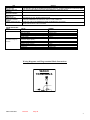
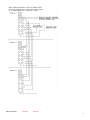
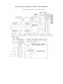
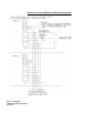
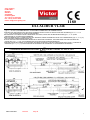
Victor Lighting
PO Box 5571
Glasgow
G52 9AH
SCOTLAND
United Kingdom
Tel: +44 (0) 141 810 9644
Fax: +44 (0) 141 810 9642
E-mail: info@ victor-lighting.com
1180
EXCALIBUR VL24E
EXPLOSION PROTECTED LUMINAIRE WITH INCREASED SAFETY, ENCAPSULATION AND FLAMEPROOF PROTECTIONS
(type ‘e’, ‘m’ and ‘d’) INCORPORATING AN INTEGRAL EMERGENCY DC POWER SUPPLY.
LUMINAIRE ANTI EXPLOSIONS AVEC SÉCURITÉ OPTIMISÉE, ENCAPSULATION ET PROTECTIONS ANTI INCENDIE (type « e », « m » et
« d ») – AVEC ALIMENTATION CC DE SECOURS INTÉGRÉE.
EXPLOSIEVRIJE LICHTARMATUUR MET VERBETERDE VEILIGHEID, AFDICHTING EN BRANDVEILIGHEID (type ‘e’, ’m’ en ‘d’) MET
INGEBOUWDE DC NOODSTROOMVOORZIENING
EKSPLOSJONSBESKYTTET LYSARMATUR MED ØKT SIKKERHET, INNKAPSLINGSBESKYTTELSE OG FLAMMESIKRING (type "e", "m" og "d")
MED INTEGRERT NØDSTRØMFORSYNING (DC).
LEUCHTE FÜR EXPLOSIONSGEFÄHRDETE BEREICHE MIT ERHÖHTER SICHERHEIT, VERGUSSKAPSELUNG UND DRUCKFESTER
KAPSELUNG (Typ ‚e’, ‚m’ und ‚d’) MIT EINGEBAUTER GLEICHSTROM-NOTSTROMVERSORGUNG.
LUMINARIA PROTEG IDA FRENTE A EXPLOSIONES SEGURIDAD AUMENTADA, PROTECCIONES DE ENCAPSULACIÓN Y A PRUEBA DE
INCENDIOS (tipo ‘e” y “m” y “d”) QUE INCORPORA UN SUMINISTRO DE CORRIENTE CC DE EMERGENCIA INTEGRADO.
VL24E IP66/67 BAS00ATEX2191 T100°C
IOM VL24E Exe
Issue 05
II 2GD Ex emd IIC T4 –10°C to +55°C
May 09
1
IMPORTANT
1.
2.
3.
4.
Read this leaflet carefully before commencing to install the luminaire and retain it for future reference.
Check the rating label to ensure that the luminaire is suitable for the supply provided.
The luminaire must be installed in accordance with the recognised code of practice e.g. EN60 079.
High voltage insulation testing may be carried out, but the test voltage must not exceed 500V DC.
WARNING: Any faults to earth within the luminaires may result in permanent damage to the electronic control unit. This possibility
can be avoided by shorting the live and neutral cables together and applying the test voltage between this connection and earth.
5. The luminaire MUST be earthed
6. The operating temperature range for the luminaire is shown on the rating label. The luminaire should not be used outside this range.
7. If the luminaire is to be installed in areas of high vibration, please consult the manufacturer.
8. Under NO circumstances should a luminaire be opened, even when isolated, when an explosive gas or dust environment is present.
9. Do not use excessive force on plastic components.
10. The luminaires are designed and constructed to EN60598.
11. Prices and design are subject to alteration without notice. All products are sold subject to our conditions of sale, copies of which are
available on request. We reserve the right to change characteristics of our products. All data is for guidance only.
GENERAL INSTALLATION NOTES.
1. Do not attempt installation until you are familiar with all warnings , precautions and procedures within this instruction sheet.
2. Refer to the wiring diagrams for correct installation.
3. Do not over tighten fasteners into plastic parts.
4. Ensure that the mains cable connectors are correctly secured to the terminal block(s). Only one conductor should be fitted to each terminal
block. If MK6 terminal block is fitted, all screws should be fully tightened whether a conductor is fitted or not. For Wago terminal block type
see figure 1.
5. Blanking plugs and cable glands must be of the correct type and must be fitted to the manufacturer’s specification to ensure that the seals
prevent the ingress of moisture or dust and so maintain the luminaire’s IP rating.
GENERAL MAINTENANCE NOTES.
1. IMPORTANT. Isolate the luminaire from both switched and unswitched mains supplies before carrying out any maintenance work.
2. Lamps must be changed at the intervals recommended by the lamp manufacturer.
3. It is essential that all luminaires together with their associated cables, glands, etc. which make up the installation are maintained in such a
manner as to ensure the integrity of the protection to which it is designed. BS5345 recommends initial and periodic inspections with suitable
recording of results and actions taken.
4. The frequency of inspection must be determined by the user, but should be regular enough to ensure that the luminaire installation
continues to operate in the designed manner. The more onerous the operating conditions, the more frequent the inspections should be. It is
recommended that the interval between inspections should not exceed two years.
5. Plastic components may be cleaned with water containing a small amount of detergent, followed by a clean water wash. Surplus water can
be wiped off plastic components, but they should not be wiped or polished with a dry cloth to avoid a build up of static electricity.
6. IMPORTANT. All components that are replaced must be in accordance with the manufacturer’s specification. Failure to use such
components invalidates the certification, approval and warranty of the luminaire and may make it dangerous. NO modification should be
made to the luminaire without the knowledge and approval of the manufacturer. If in doubt, refer to the manufacturer.
TECHNICAL DATA
Maximum mains cable size is 6mm2
Total circuit watts: 2x18W= 42W: 2x36W=76W, when using bi-pin lamps with G13 caps
Total circuit watts: 2x18W=42W: ,2x36W=76W, when using single pin lamps with Fa 6 caps.
Maximum inrush current at switch on is 30A (18W) and 40A (36W) for < 1ms
Power factor correction is better then 0.95
Emergency duration typically 3 hours at 20°C
The luminaire housing and lens are made polycarbonate, the reflector is made from painted stainless steel or Zinc plated Epoxy painted Mild
Steel. The user must ensure that these materials are suitable for the atmosphere the luminaire will be installed in.
SPECIAL NOTES
1. The cable glands used should comply with the requirements of the Code of Practice for increased safety (type ‘e’) installations. They
should maintain at least IP54 protection and have an impact strength of 7Nm
2. The battery must not be removed from the battery tube assembly in a hazardous area.
3. NiCd batteries have a reduced charge acceptance efficiency at temperatures continuously above 30°C, so a reduction in emergency
discharge durations may be experienced.
4. The batteries are supplied discharged and must be charged for 48 hours and discharged three times before reaching full charge capacity.
5.
When the luminaire is isolated from the mains supply, one lamp will operate from the integral battery supply at reduced brightness. This
battery has to be isolated before working on the luminaire. This is achieved by removing the ballast housing cover or lamp envelope
assembly. This action will operate a microswitch which isolates the battery.
6. The emergency operation of the luminaire should be tested regularly in accordance with the relevant code of practice, e.g. BS 5266
INSTALLATION AND MAINTENANCE NOTES SPECIFIC TO THIS PRODUCT.
WIRING - The luminaire is pre-wired for maintained (normally on) operation. The Live supply from the mains should be connected to the terminal
marked ‘L’. For switched operation, the link between the L and Ls terminals must be removed. The permanent Live supply is then connected to
the ’L’ terminal and the Switched Live to the ‘Ls’ terminal. On through-wired units these connections are duplicated in the second terminal
chamber.
REPLACING SINGLE PIN LAMPS. - To remove the lamps, lift and rotate the lamp retainer one way and remove a lamp. Then move the other
way to remove the second lamp. Replace using the reverse procedure and if 26mm lamps are being used, fit the collars supplied with the
luminaire to the lamps.
FITTING BI-PIN LAMPS. - The lamp carrier assembly is removed from the lamp envelope by operating the quick release mechanism and with
drawing the assembly. Lamps are inserted by pressing the button on each lampholder and sliding the lamp pins down the lampholder slot until
they engage in their recesses in the contacts. When both lamps have been fitted, the lamp carrier assembly can be re-fitted to the envelope.
Ensure that it is orientated correctly and that the quick release mechanism engages in its slot.
REMOVE BATTERY TUBE, CABLE AND BALLAST HOUSING COVER ASSEMBLY.
IOM VL24E Exe
Issue 05
May 09
2
Isolate the luminaire from the mains and battery supply as described above. Disconnect the red and black wire that leads from the ballast to the
microswitch terminal block at the terminal block. (Note that the positions of the wires are marked on the ballast housing cover for re-assembly.)
Loosen, but do not remove, the bolts securing the battery tube brackets. Now remove the clips on the ballast housing lid securing straps and
remove the battery assembly by moving it first one way (slots in the mounting brackets allow movement) then the other. The battery tube/ cable/
ballast housing cover assembly can now be fully removed to a safe working area before carrying out any work on it. It is important that a
replacement assembly should be fitted immediately. The luminaire must not be left in the open condition and must not be energised from the
mains when open.
REPLACING THE BATTERY.
Remove the battery assembly as described above. Remove the two screws at the cable end that secure the bracket and plastic moulding to the
tube. Carefully withdraw the end moulding from the battery tube, ensuring that the internal wiring is not stressed. (A slight rotation, a few degrees
either way, can help removal. Do not twist in one direction only as the wires may become damaged, short circuit the battery and blow it’s fuse.)
Disconnect the battery wires one at a time by inserting a screwdriver through the holes in the side of the moulding. As each wire is removed it
should be insulated. Failure to do this may result in a short circuit.
Remove the moulding at the other end of the tube to expose the fuse assembly. The battery may now be removed from the tube. Do not use the
battery wires to aid removal.
Replacing the battery is the opposite procedure, but when replacing the battery in the tube it is important to ensure that the sponge rubber strips
are inserted around the inside of the tube at either end. The fuse should also be fitted so that the flat side locate correctly in its moulding. Finally
ensure that the new battery leads are connected to the correct terminals in the end moulding. (Red to + and black to -)
REPLACING THE BATTERY FUSE.
Remove the battery tube / cable / ballast cover assembly, and expose the fuse as described above. Care must be taken when handling /
removing the fuse connections to prevent the risk of short circuit. Remove the soldered receptacles from each terminal blade of the fuse in turn
and fit to a new fuse assembly. The receptacles must be soldered in place on the new fuse to achieve the approved connection. Re-assemble
the battery tube as described above.
REPLACING LAMPHOLDERS.
The monopin lampholders form part of a flameproof enclosure and must be replaced if damaged. To gain access to the lampholders remove the
lamp envelope and ballast housing cover as described earlier. To remove a lampholder, push the lampholder retaining plate against the
lampholder spring, rotate through 90°C and release. The lampholder can then be withdrawn and its cable disconnected. Replacement is a
reverse of this procedure.
REPLACING THE ELECTRONIC BALLAST.
Disconnect from the mains supply (make sure both Live and Live Switched supplies are isolated). Remove the ballast housing cover and
suspend from its straps. Disconnect the mains wires from the ballast terminal block and also the battery red and black leads from the microswitch
terminal block. Disconnect the earth bonding cable from the connection on the electronic ballast (leave attached to the gland plate). Remove the
lampholders as described above. The electronic ballast can now be removed by slackening two screws at one end of the unit and the two nuts at
the other end. The three cables from the electronic ballast can now be removed from the lampholders. Replacement is a reversal of this
procedure.
REGULAR MAINTENANCE AND INSPECTION
All luminaires and installations, including cable, conduit and other associated systems which make up an installation must be maintained in such
a way to ensure the integrity of the protection to which it was designed to have. BS5345 makes particular reference to this subject,
recommending initial and periodic inspections, with suitable recording of
OPTIONAL BATTERY MANAGEMENT SYSTEM (GREEN & RED LED’S FITTED)
The Optional battery management system (if fitted) monitors the battery capacity and can detect fault conditions within the system
Automatic Conditioning - The battery is automatically conditioned after initial commissioning so that after 24hours it is completely discharged
and recharged. Normal test cycles start after that so that the first test takes place after randomly selected period.
Lamp test - First lamp test takes place on random point within 1-168 hours after connecting unit to mains. After that the lamp test takes place
every 168 hours (7 days).
Lamp is considered faulty if the lamp doesn’t light up within 3 seconds after starting of the lamp test.
Every 3 seconds or longer mains supply failure is considered as a lamp test, but the scheduled time of lamp test is not affected.
Battery test - First battery test takes place on random point within 72-2400 hours after connecting unit to mains. After that the battery test takes
place every 2400 hours (100 days).
Battery is considered faulty if the deep discharge protection operates before the 3 hours operation has completed.
Battery test is also a lamp test. If the lamp doesn’t light up within 3 seconds after starting of the battery test, the battery test is cancelled and the
lamp is considered as faulty.
If there has been a mains supply failure 24 hours or less prior to scheduled battery test, the test is delayed to take place 24 hours after the
returning of the mains supply. This ensures that the battery is fully charged prior to test.
Every mains supply failure is considered also as a battery test if there has been an uninterrupted 24 hours charging of the battery prior the
failure. If battery doesn’t last for 3 hours, it is considered faulty. This does not affect the timing of the scheduled battery test though.
Emergency Blackstart - There is an indication added for the blackstart circuit, when activated the red LED flashes each 10 seconds.
When emergency blackstart is required you must order battery control management.
The electrical wiring will consist of two connections from the control gear out to the terminal block, the connections will be connected by a comb
fitted at assembly. This link should be removed, and external wiring to be connected across to a single pole switch, SWITCH TERMINAL NOT
TO BE CONNECTED TO EARTH. Closed circuit is normal, open circuit prevents automatic operation of the emergency function.
Up to ten luminaires can be connected in parallel to one switch, using 500m of cable.
The blackstart as well as automatic emergency functions can start with normal mains power present as well as without mains power, the
emergency light can be switched on while the whole system power is still dead. Blackstart is not possible with a completely discharged battery
and no mains being present. The emergency function can be switched on/off whilst in emergency operation, using the switch. Return to
emergency operation is instant. The change to lamp off when put into blackstart mode may be delayed for up to 60 secs,
IOM VL24E Exe
Issue 05
May 09
3
LED
GREEN LED ON
RED LED OFF
GREEN & RED LED
BLINKING
GREEN LED OFF
RED LED BLINKING
GREEN LED OFF
RED LED ON
GREEN LED OFF
RED LED FLASHING
(10SEC)
GREEN & RED LED OFF
TROUBLESHOOTING
FAULT
‘Dead’ luminaire
No emergency function,
or limited emergency
function
STATUS
SYSTEM HEALTHY:
THE BATTERY WILL BE CHARGED WITH ENOUGH CAPACITY TO MEET EMERGENCY DURATION TIMES.
THE UNIT IS PERFORMING DURATION AND EMERGENCY OPERATING TESTS
LAMP FAULT.
BATTERY FAULT
BLACKSTART ACTIVE, MAINS POWER FAILURE
AWAITING EMERGENCY BLACKSTART SWITCH TO BE TURNED ON.
MAINS OFF: UNIT IS IN EMERGENCY MODE OR INHIBITION IS ACTIVATED
MAINS ON: BATTERY IS NOT CHARGED
CAUSE
REMEDY
No mains supply
Both tubes faulty
Lamp envelope not engaged
Microswitch actuator damaged or missing
Faulty ballast
Battery has not yet been cycled to achieve
minimum charge capacity
Battery not connected
Battery fuse blown
Battery not fully charged
Microswitch actuator damaged or missing
Failed lamp
Faulty ballast
Connect mains
Replace tubes
Engage
Replace
Replace
Cycle battery as per the instruction leaflet
Check wiring
Check fuse in battery stick
Charge
Replace
Replace lamp
Replace
Wiring Diagrams and Wago terminal Block Instructions
WAGO
TERMINALS
IOM VL24E Exe
Issue 05
May 09
4
IOM VL24E Exe
Issue 05
May 09
5
IOM VL24E Exe
Issue 05
May 09
6
HEALTH AND SAFETY AT WORK etc. ACT 1974
In the United Kingdom all equipment must be installed, operated and disposed of (as required) within the legislative requirements
of the Health and Safety at Work etc. Act 1974. Leaflet No. HSS L1 refers to the Company’s obligation and is available on
request. It is the responsibility of the user to select, install, operate and maintain the equipment in accordance with the relevant
legislation and appropriate codes of practice
CE Mark
ATEX Declaration
The CE marking of this product applies to "The Electrical
Equipment (Safety) Regulations 1994", "The Electromagnetic
Compatibility Regulations 1992", the “Waste Electrical and
Electronic Equipment Regulations 2006” and the "Equipment and
Protective Systems intended for use in Explosive Atmospheres
Regulations 1996". [This legislation is the equivalent in UK law
of EC directives 73/23EEC, 89/336/EEC and 2002/96/EC
respectively].
The Equipment is declared to meet the provisions of the ATEX
directive (94/9/EC) by reason of the EC Type Examination and
compliance with the Essential Health and Safety Requirements.
I MacLeod Technical Manager
Disposal of Material
Any disposal must satisfy the requirements of the WEEE directive [2002/96/EC] and therefore must not be treated
as commercial waste. The unit is mainly made from incombustible materials. The control gear contains plastic,
resin and electronic components. All electrical components may give off noxious fumes if incinerated.
To comply with the Waste Electrical and Electronic Equipment directive 2002/96/EC the
apparatus cannot be classified as commercial waste and as such must be disposed of or
recycled in such a manner as to reduce the environmental impact.
IOM VL24E Exe
Issue 05
May 09
7
EC - Declaration of conformity
VICTOR LIGHTING
CE – Dèclaration De Conformitè
EG - Konformitätserklärung
EXCALIBUR VL24E
VL24E IP66/67 BAS00ATEX2191 T100°C
II 2GD Eex emd IIC T4 –10°C to +55°C
VICTOR LIGHTING
Hereby declare our sole responsibility that the product which is the subject of this declaration is in
conformity with the following standards or normative documents.
Erklären in alleiniger Verantwortung, daß das Product auf das sich diese Erklärung bezieht, mit der/den
folgenden Norm(en) oder normativen Dokumenten Ubereinstimmt.
Déclarons de notre seule responsabilité, que le produit auquel cette déclaration se rapporte, est
conforme aux norme(s) ou aux documents normatifs suivants.
Number and date of standard
Directive description
Nr. Sowie Ausgabedatum der Norm
Bestimmungen der Richtlinie
No. Ainsi que date d’emission des normes. Prescription de la directive
EN 50014 (1998)
EN 50018 (2000)
94/9 EC : Equipment and protective systems intended for
use in potentially explosive atmospheres.
EN 50019 (2000)
94/9 EG: Geräte und Schutzsysteme zur
bestimmungsgemäßen Verwendung in
explosionsgefährdeten Bereichen
EN 50028 (1987)
EN 50281 (1999)
94/9 CE: Appareils et systèmes de protection destinés a êtré
utilisés en atmosphères explosibles.
EN50082 (1992)
EN55015 (1993)
EN 60555-2 (1987)
89/336 EEC: Electromagnetic Compatability
89/336 EWG: Elektromagnetische Verträglichkeit
89/336 CEE: Compatabilité électromagnétique
Notified Body:
SIRA Certiifcation Services (0518)
Rake Lane
Eccleston
Chester
CH4 9JN
Ian MacLeod
(Technical Manager)
5th August 2005
Victor Lighting
PO box 5571
Glasgow,
G52 9AH
Scotland
Telephone
Fax
Email
Web
:
:
:
:
+44 (0) 141 810 9644
+44 (0) 141 810 9642
[email protected]
www.victor-lighting.com
For Technical support, please contact [email protected]
Registered Office:
Mitre House,
160 Aldersgate Street,
London,
EC1A 4DD
Registered No: 669157
Note :
Victor Lighting reserve the right to amend characteristics of
our products, and all data is for guidance only.
Technical Bulletin 09/01
Dated: 08.04.09
Subject: Update to Battery Monitoring & Blackstart Wiring on Excalibur VL24E
The Excalibur VL24E Emergency Luminaire control gear has been altered due to continual improvement
of the circuit and a change in supplier.
The electronic control gear which runs the lamps and controls the battery charging and monitoring has
been altered to comply with the industry recognised standards. The method of battery self test &
indication has been updated to be more user friendly. The functionality of the new self testing is
described in detail below:
Battery Control Management LED Indication Table
LED
GREEN LED ON
RED LED OFF
GREEN & RED LED
BLINKING
GREEN LED OFF
RED LED BLINKING
GREEN LED OFF
RED LED ON
GREEN LED OFF
RED LED FLASHING
(10SEC)
GREEN & RED LED
OFF
STATUS
SYSTEM HEALTHY:
THE BATTERY WILL BE CHARGED WITH ENOUGH CAPACITY TO MEET
EMERGENCY DURATION TIMES.
THE UNIT IS PERFORMING DURATION AND EMERGENCY OPERA TING TESTS
LAMP FAULT.
BATTERY FAULT
BLACKSTART ACTIVE, MAINS POWER FAILURE
AWAITING EMERGENCY BLACKSTART SWITCH TO BE TURNED ON.
MAINS OFF: UNIT IS IN EMERGENCY MODE OR INHIBITION IS ACTIVATED
MAINS ON: BATTERY IS NOT CHARGED
This change also means that sites utilising the Blackstart or Remote Inhibition functionality now require a
two wire operation, from and to a switch (see typical wiring diagram below).
This change allows the Excalibur fitting to be used as a replacement, within an existing circuit, for the
majority of our competitors.
However, the new ballast/inverter is not a direct replacement for the previous version, as the previous
blackstart utilised the return of the ground/earth connection for the return of the signal, to operate the
emergency lamp by control of a switch.
Although this system did operate satisfactorily, if there was an earth leakage from other products on the
line or a fault to earth, when the switch was closed for operation, this could possibly cause problems with
the operation or the circuit board.
New Emergency Blackstart - An indication has been added for the blackstart circuit, when activated the
red LED flashes each 10 seconds.
When emergency Blackstart is required you must order battery control management, /BMC.
The electrical wiring will consist of two connections from the control gear out to the terminal block, the
connections will be connected by a comb fitted at assembly. This link should be removed, and external
wiring should be connected across to a single pole switch, THE SWITCH TERMINAL MUST NOT TO BE
CONNECTED TO EARTH. Closed circuit is normal, open circuit prevents automatic operation of the
emergency function.
Up to ten luminaires can be connected in parallel to one switch, using 500m of cable.
The blackstart as well as automatic emergency functions can start with normal mains power present as
well as without mains power, the emergency light can be switched on while the whole system power is
still dead. Blackstart is not possible with a completely discharged battery and no mains being present.
The emergency function can be switched on/off whilst in emergency operation, using the switch. Return
to emergency operation is instant. The change to lamp off when put into blackstart mode may be delayed
for up to 60 secs..
Old Emergency Wiring Diagram for Battery Control Management
Remote Connetion Details for Blackstart Operation
John T Campbell
Technical Sales Engineer
05.05.09