1
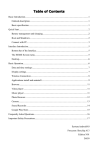
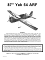
87” Yak 54 ARF WARNING A radio-controlled model is not a toy and is not intended for persons under 16 years old. Keep this kit out of the reach of younger children, as it contains parts that could be dangerous. A radiocontrolled model is capable of causing serious bodily injury and property damage. It is the buyer's responsibility to assemble this aircraft correctly and to properly install the motor, radio, and all other equipment. Test and fly the finished model only in the presence and with the assistance of another experienced R/C flyer. The model must always be operated and flown using great care and common sense, as well as in accordance with the Safety Code of the Academy of Model Aeronautics (5151 Memorial Drive, Muncie, IN 47302, 1-800-435-9262). We suggest you join the AMA and become properly insured prior to flying this model. Also, consult with the AMA or your local hobby dealer to find an experienced instructor in your area. Per the Federal Communications Commission, you are required to use only those radio frequencies specified "for Model Aircraft." LIMITED WARRANTY Lanier RC has inspected and certified the components of this aircraft. The company urges the buyer to perform his own inspection, prior to assembly, and to immediately request a replacement of any parts he believes to be defective for their intended use. The company warrants replacement of any such components, provided the buyer requests such replacement within a period of 30 days from the date of purchase and provided the defective part is returned, if so requested by the company. No other warranty, expressed or implied, is made by the company with respect to this kit. The buyer acknowledges and understands that it is his responsibility to carefully assemble the finished flying model airplane and to fly it safely. The buyer hereby assumes full responsibility for the risk and all liability for personal or property damage or injury arising out of the buyer's use of the components of this kit. Lanier R/C, INC. P.O. Box 458 Oakwood, Ga. 30566 PH 770 532 6401 © copyright 2005 Lanier R/C ©copyright 2005 Congratulations on your purchase of the 87” Yak 54 ARF. Every effort has been made to produce a lightweight, straight, easy to assemble aircraft. Because of its oversize control surfaces which are double beveled to allow for extreme throws, great care must be taken in the set-up and flying of this airplane. Quality hardware components have been provided to allow for 3D set-up while maintaining adequate mechanical advantage to eliminate flutter. It is your responsibility as an advanced pilot to fly the aircraft in an intelligent manner. THROTTLE MANAGEMENT IS A MUST!!!!!!! Lanier RC has flown the 87” Yak 54 ARF through a very rigorous flight-testing schedule and have stressed the airframe beyond all practical parameters without a single failure. Lanier RC will NOT warranty the 87” Yak 54 ARF against flutter due to improper set-up or excessive speed maneuvers. having said that, we believe you will find the 87” Yak 54 ARF to be one of the most responsive, in-the-grove aircraft on the market. Just remember to use common sense when flying this high performance machine. We are very proud of the construction of the 87” Yak 54 ARF and all of our other ARF aircraft. Each aircraft is jig built to insure a straight true airframe. Every effort is made to build as light an aircraft as possible. As with any professional builder, glue is used sparingly. Please take a moment during assembly and run a bead of CA or aliphatic resin into the high stress joints that you can reach such as the landing gear plate, servo mounting trays, wing hold down blocks, Firewall, etc. Also, during the course of shipping from the manufacturer to our facility in the United States, it is not uncommon for the aircraft to experience several changes in climate. This may cause the iron-on covering to develop wrinkles. This is not a fault of the manufacturer. Please take a few minutes with your heating iron and heat gun to iron down the seams and re-shrink the covering where needed. The results will be a beautiful aircraft with a breathtaking finish that you will be proud to display at your flying club. Before beginning assembly of your 87” Yak 54 ARF, we highly recommend that you study this manual in its entirety. You should begin planning your radio installation based on your choice of engine and equipment from the beginning. Because the 87” Yak 54 ARF is intended for those with some degree of modeling experience, every minute detail will not be covered. This is not a basic trainer. Assembly of this aircraft will be easy for the experienced modeler, and by following the instructions within this manual and using the skills you’ve gained during your modeling career you will be able to produce a first class aircraft. Building supplies needed Hobby knife w/#11 blades Thin CA Medium CA Canopy glue 30 minute epoxy Thread lock Diagonal wire cutters Pliers Assorted drill bits Various sized screwdrivers( both Phillips and standard head) Tape measure Dry-erase marker Paper towels Rubbing alcohol Electrical tape 4-40 Tap & Die Set 3/32, 7/64, 9/64 & 3mm Allen wrench Wax Paper 3-1 Oil Note: Thread lock must be used where ever any machine bolts are threading into any type of nuts. If you do not use thread lock the bolts could become loose and fall out in flight. 2 ADHESIVES & GLUING TECHNIQUES ITEMS NEEDED TO COMPLETE THIS AIRCRAFT 1 24” Gasoline fuel Line CA adhesives are specially formulated to firmly glue the plywood, hardwood, and balsa used in your model and to withstand the vibration and stresses of high performance flight. However, there are times, such as when you are installing the stabilizer and fin on the fuselage and want more set-up time for careful alignment and positioning, then you should use epoxy. Occasionally, you also will want to use thin CA, which "wicks" into the surrounding areas. Aliphatic resin glue or similar water-based glues can also be used, but they will add to the assembly time because they dry so much more slowly than CA glue. Remember, when ever using any CA, you must be careful to read instructions thoroughly, as you will have only seconds for positioning of parts. Be sure to trial fit parts together before gluing. Also, never use watery THIN type CA glue for gluing plywood and hardwood parts. Thin CA's do not adequately bond these areas. CAUTION 1 20 to 24 oz Gasoline fuel tank 1 1 4 Engine 3.2 to 4.9cc (50cc to 80cc) We used a Desert Aircraft DA 50 Pt# 2123 Slimline Muffler W/O Smoke RADIO GUIDANCE SYSTEM (6 CHANNEL MINIMUM REQUIRED WITH 9 SERVOS 100 OZ TORQUE REQUIRED) 11” Y-HARNESS (3 Aileron & 1 Rudder) 2 18” AILERON SERVO EXTENSION WIRES 3 1 24” ELEVATOR/ RUDDER SERVO EXTENSION WIRES CA ACCELERATOR 1 2 OZ. BOTTLE CA MEDIUM GLUE 1 1/2 OZ. BOTTLE CA THIN GLUE 1 30 MINUET EPOXY 1 1/2” FOAM RUBBER 1 4” SPINNER Some people may experience an allergic reaction when exposed to fumes from CA glue or epoxy. As with paints, thinners, and solvents, it is always important to use glues only where there is adequate ventilation to carry fumes away. A fan is recommended. Also, special care must be taken when using CA, as it will bond skin as well as other surfaces. Before using any CA, carefully read all label precautions. When using CA, protective eye-wear and care in keeping the glue away from the face is highly recommended. If CA does happen to get into the eye, hold lid open and flush with water only. Seek immediate medical attention. OPTIONAL: 1 PILOT FIGURE CONSTRUCTION TIPS 8 SERVO ARM EXTENSIONS IMPORTANT: ALWAYS READ A FEW STEPS AHEAD. This will alert you to coming instructions and will help you plan accordingly. NOTE: The 87” Yak 54 ARF covering closely matches Bright Yellow (872), Flame Red (883), Black (874), and White (870) Oracover. COVERING The 87” Yak 54 ARF is covered in a premium polyester film chosen by many of the world's top flyers for its beauty, toughness, and ease of application and repair. It is not uncommon for ARF's to develop a few wrinkles in transit. If this is true of your model, the situation is easily corrected. Before you begin putting the pieces together, run around the edge of the seams first then over the surface of each section with an iron (either specially designed for airplane use or the more cumbersome household iron). Apply the heat (set at about 350° F), following along with a soft cloth and pressing down on the covering as you go around. This will more firmly set the covering adhesive into the wood and keep your aircraft covering tight and smooth in the future. Once you have ironed the seams stay away from them with the heat or the covering will slide when you try to shrink the middle. If this happens the wrinkles will not come out of the covering. 3 WING ASSEMBLY 4. AILERON INSTALLATION 1. Collect the following parts: (1) Left wing (1) Right wing (1) Left aileron (1) Right aileron (10) hinges 2. Locate the pre-drilled aileron hinge holes in both wing halves. Using a 1/4” drill, drill each hole 1/8” deep. This will allow the center of the hinge to be inserted half way into each of the surfaces. Repeat this process with the ailerons, making sure all hinges insert half way. 5. 6. Select the aileron for the wing half on which you are working. Mix up a liberal amount of 30 minute epoxy. Repeat for each of the other hinges for that aileron. Working quickly, place some epoxy on the second half of each hinge and insert the aileron into the wing. Slide the aileron toward the wing until no gap remains between the aileron and the wing. When satisfied with the alignment, flex the aileron up and down to confirm that the hinges are working freely. remove any excess epoxy. Apply a few strips of masking tape to keep the pieces in place. Allow to dry before flexing the aileron. Working with 1 hinge at a time, place a dab of epoxy and insert the hinge half way into one of the aileron holes. Repeat the above steps for the other half of the wing. AILERON SERVO INSTALLATION 1. 3. Place 1 drop of oil on each of the hinge joints at the center. This is to keep the hinges loose and prevent epoxy from sticking at the joint. Collect the following parts: (1) (1) (4) (2) (4) Left wing Right wing Servos 18” Servo Extension Servo “Y” Harness Locate the two servo holes in the bottom of wing. Carefully cut the covering over the servo holes. Caution: Do not get any oil on the length of the hinge or it will not glue into the surface. 2. 4 3. Attach the 18” servo extension to the outer servo. 6. IMPORTANT! To ensure that any connections located inside the wing will not come loose, either when the wires are pulled, or during flying, always tape them securely together with electrical tape. Pull the second servo wire out of the wing root rib. Plug the two aileron servos into a “Y” harness. Always tape them securely together with electrical tape. Repeat for the other wing half. CONTROL HORN PART NAMES Nylon Adjustable Control Horn Nylon Nut 4. Starting from the outer servo hole, insert the servo extension and the servo wire into the servo hole. Allow the wire to fall straight down through though the wing till it exits the root rib. Nylon Cup Washer 6-32 x 2-1/4” Allen head Bolt AILERON CONTROL HORN INSTALLATION 1. Collect the following items (8) (8) (4) (4) (4) (4) 4-40 Metal Clevis 4-40 Hex Nut Clevis Clip 4-40 x 3-1/4" Double Threaded Wire 6-32 x 2-1/4” 3mm socket head bolt Nylon Adjustable Control horns (4) Nylon Nut (4) Nylon Cup Washer Aileron Wing Tip 5. Tape the end of the plug to the root rib. Mount the inner aileron servo into the wing. 5 2. With the aileron servo in place, make a mark on the aileron at a 90º degree angle to the trailing edge and in line with the servo. Look for the control horn hard point under the covering. This is the location for the control horn. 5. Thread the 4-40 x 3-1/4” double threaded rod into the nylon adjustable control horn. Place a 4-40 hex nut and a metal clevis on the other end of the threaded rod. Mount the clevis to the servo arm and place the clevis clip on the clevis. 6. Repeat 1 thru 5 for the second aileron. FUSELAGE HATCH 3. 4. Using a 1/8” drill, drill half way through the aileron hole from both top and bottom till the drill passes through the aileron. Insert the 6-32 x 2-1/4 allen head bolt into the top of the aileron. Thread the bolt all the way till the head is flush with the top of the aileron. On the bottom of the aileron, place first the cup washer then the nylon nut onto the 6-32 bolt. Using a 3 mm metric allen wrench tighten the nylon nut all the way down till it rest in the cup washer and is tight to the aileron. The top front half of the fuselage is a hatch. Remove the 4-40 socket head bolts on the side of the fuselage to disengage the hatch. ELEVATOR & RUDDER SERVOS 1. Collect the following items (2) Servos (2) 24” Servo extensions Thread the nylon adjustable control horn onto the bolt.(Note: Thread the side that you can see the cut threads in the nylon onto the bolt) 1. Locate the servo holes at the rear of the fuselage side. Remove the covering over both servo holes. Note: This is the time to decide if you will be using two servos for the rudder. 2. 6 Remove the covering over the servo hole on the other side of the fuselage Using the 24” servo extensions install all the servos facing the same direction as shown in the photo above. MOUNTING STABILIZERS 1. 1. 2. Collect the following items (2) (4) (1) (1) Stabilizers 4-40 x 1/2” Button Head Bolts Short Front Stabilizer Tube Long Rear Stabilizer Tube Locate the two holes under the stabilizer tubes in the fuselage. Remove the covering over both screw holes. Slide the short stabilizer tube into the front hole in the fuselage. Insert the long stabilizer tube in the rear hole of the fuselage. Using the 4-40 x 1/2” button head screws to fasten the stabilizer to the fuselage side. TAIL WHEEL ASSEMBLY 1. Collect the following items (2) (4) (1) (1) (1) (1) (2) (2) Springs 1/8 Adjustable Horn Brackets Tail Wheel Bracket Tail Wheel Axle Tail Wheel Wheel collar with Set Screw 6-32 all threaded short shafts Brass Tail Wheel Axle Supports with Set Screws Locate the tail wheel axle and one of the brass tail wheel supports with only one threaded hole. Insert the axle through the brass tail wheel support and tighten the set screw like shown above. Note: Always use thread lock on these screws before flying 3. Repeat for the other side of the stabilizer. 1. Note: Use thread lock on the set screw. 7 Insert the axle shaft through the hole on the tail wheel bracket. TAIL WHEEL Collect the following items (1) (2) (1) (2) Tail wheel bracket #4 x 3/4” philip head screws Small tail wheel Wheel collars with set screws 1. Draw a centerline on the bottom of the fuselage where the tail wheel bracket will mount. 2. Mark the tail wheel bracket mounting hole locations while keeping the first bend on the rudder hinge line. Drill two 1/16” holes on the marks you just made.(Use thin CA glue to harden the holes) Using the #4 x 3/4” philip head screws mount the tail wheel bracket. Install the tail wheel and the wheel collars onto the bracket. 1. 2. Thread the two threaded rods in to the brass axle. Note: Use thread lock on the set screw. 3. Place the brass tail wheel support on the top of the axle and tighten the set screw like shown above Note: Use thread lock on the set screw. 3. Thread on to each end of the threaded rod a 1/8” adjustable control horn 3. 8 HINGING RUDDER 1. Collect the following items (1) (4) (1) (2) (2) (2) (2) Rudder Hinges 6-32 x 3” All Threaded Rod 6-32 Locking Hex Nuts #6 Washer Nylon Adjustable Control Horn Nylon Adjustable Horn Bracket 3. Place on both ends of the threaded rod a Nylon Adjustable Control Horn. Place the spring between the rudder control horn bracket and the tail wheel tiller arm on top of the wheel. INSTALLING MAIN LANDING GEAR 1. Collect the following items: (6) 6-32 x 3/4” Socket Head Screw (1) Main Aluminum Landing Gear 1. Glue the Rudder to the fin the same way you did the ailerons. Make sure that the top of the rudder will not rub on the top of the fin. 2. 2. . Find the landing gear slot on the side of the fuselage. Insert the the landing gear through the slot . Drill a 1/8” hole located at 3/4” back from the hinge line and 1/2” up from the bottom of the rudder. Insert the 6-32 x 5-1/2” all threaded rod and center it using the #6 washer with a 6-32 locking hex nut. Front 3. 9 Using the 6-32 bolts and thread lock, mount the landing gear in the fuselage HINGING THE ELEVATORS 1. Collect the following items: (2) Elevators (8) Hinges 2. 3. 2. the inner most hinges on each elevator will have to be trimmed so that the elevator will fit flush to the stabilizer. Thread the 4-40 pushrod into the nylon adjustable control horn Thread the 4-40 hex nut and the 4-40 metal clevis onto the other end of the pushrod. Connect the clevis to the servo arm. Place the clevis clip onto the clevis. Repeat steps 2 & 3 for the other rudder servo. ELEVATOR PUSHRODS 1. Collect the following items: (2) 4-40 x 3-1/4” Double Threaded Pushrod (2) 4-40 Hex Nuts (2) 4-40 Metal Clevis 3. 4. 5. Insert the hinges into the hinge hole in the stabilizers and the elevators (2) Clevis Clips Make sure that the hinges fits completely into the stabilizer and the elevator. (2) Nylon Adjustable Horn Bracket Take the elevators and the stabilizers and just like you did for the ailerons pre-drill each of then hinge holes. Place a drop of oil on each of the hinge joints. Tape the elevators to the stabilizers till dry. (2) Nylon Adjustable Control Horn (2) Nylon Nut (2) Nylon Cup Washer (2) 6-32 x 3” Flat Head Screw Mix up some 30 minute epoxy and glue each of the elevators to the stabilizers. RUDDER PUSHROD 1. Collect the following items: (2) 4-40 x 3-1/4” Double Threaded Pushrod (2) 4-40 Hex Nuts (2) 4-40 Metal Clevis (2) Clevis Clips 2. 10 Position the control horn bolt so that it is 1/2” back from the hinge line and 1/2” from the end of the elevator. Using a 9/64" drill bit, make a hole in the elevator through to the top side. HINT: Drill the hole from the bottom half way. Then measure and mark the top of the aileron and drill down to the hole from the top of the aileron. 3. 4. 3. Insert the 6-32 x 3” screw from the top through the elevator. Place the nylon cup washer and nylon nut on the bolt and tighten Screw the nylon adjustable horn bracket on to the bolt. Thread the 4-40 pushrod into the nylon adjustable control horn Thread the 4-40hex nut and the 4-40 metal clevis onto the other end of the pushrod. Connect the clevis to the servo arm. WHEEL AND WHEEL PANTS 1. Collect the following items: (2) (4) (4) (2) (2) (2) 5-32 x 1-1/4” Axle with Locking Nut 5/32 Wheel Collars 4-40 x 1/8” Cup Screws 4-40 Blind Nuts 4-40 x 1/2” Button Head Screws 3-1/4” Wheels 2. Mount the axle to the landing gears. Place the clevis clip onto the clevis. Repeat steps 2 thru 4 for the other elevator servo. Caution: Make sure each metal clevis is fully closed and a clip is installed before and after each flight. 3. Place the wheel pant and the wheel onto the axle. level the fuselage by blocking the tail up till it is level, then level the wheel pant. Mark the hole location on the wheel pants through the back of the landing gear. 4. Drill a 1/8” hole on the marks you just made through the wheel pant. Insert a 4-40 blind nut inside the wheel pants. 11 Landing Gear Wheel Pant Wheel Collars Wheel 5. Mount the wheel pants back on the landing gear along with the wheel collars and wheels. Center the wheel on the axle. 1. You will find both the horizontal and vertical lines marked on the firewall. ENGINE INSTALLATION The Motor you choose may have a different type installation as show. We show a Desert Aircraft DA50 motor. This motor has more than enough power to make this plane perform to its limits. The vertical line is off set to compensate for the 2 degrees right thrust. Mark your motor mount location from these marks. The front of the prop drive washer needs to be 6-1/4” away from the firewall. If you choose a more powerful motor then you must make sure that you go over all high stress joints with a white glue or a epoxy. Because of the size of propellers used in these type of engines any kind of prop strike on the ground, or any other type of object, can cause structural damage that might not be easily visible. When a accident occurs you must check for damage thought out the plane before flying. This damage can cause airframe failure at any time, so inspections must be thorough. We will not warranty any structural failures do to neglect or accidents. Caution: Always use thread lock on any bolt that is threading into metal threads. 12 Remove for carburetor breathing 2. The ignition box was mounted below where the fuel tank will be placed. FUEL TANK Note: The fuel tank must be designed for gas if you are using a DA50. 2. The motor we used was mounted on pillars off of the firewall the proper distance (6-1/4” total). You might need to shim your motor out farther. We also had to open the fuel tank hole in the firewall because the DA 50 carburetor needs “breathing room” to function properly. This hole allows the carburetor to breath through the firewall into the fuselage. 1. Construct your fuel tank. Using Rubber bands or velcro©, strap the fuel tank to the tray. 2. Using #2 x 5/16 screws, Install the fuel tank tray in front of the fiberglass wing tube. Install the fuel line line for your motor. 13 ENGINE THROTTLE INSTALLATION 1. COWL INSTALLATION 1. Collect the following items: Collect the following items: (1) 1/8” x 16” nylon tubing (1) Cowl (1) .072 x 18” Threaded Rod (4) 4-40 x 3/4” Button Head Socket Bolt (1) EZ connector (4) 1/4 x 1/4 Silicone tubes (1) Snap Nut You will have to remove any parts of the cowl that rub against the engine. Make these openings little at first and slowly make them bigger till the cowl fits over the engine without touching. Do not forget to make an opening for the needle valve and the fuel lines. (1) 4-40 x 1/8 Screw (1) Nylon Snap Link (1) Servo 2” back 2 Place a 4” strip of masking tape from the cowl screw hole back along the fuselage.. Using a pencil, draw a line straight back from the hole 2-1/2” long Measure back from the hole 2” and make a mark 3. Repeat step 2 for the remaining cowl mounting holes. 2 Install the throttle servo. Drill a 1/8” hole in the firewall in position with the throttle arm. Insert the nylon tubing in the hole. Let the tubing exit into the fuselage towards the throttle servo mount. Attach the EZ connector to the engine throttle or servo arm. Insert the pushrod into the tubing and through the EZ connector. 4. After cutting openings in the cowl to fit around the motor, mount the cowl onto the airplane and tape in place Mark a line onto the cowl following the line on the masking tape you made earlier. Note: The DA 50 has a threaded hole for a ball link to mount This is not included in the kit. Measure forward 2” from the old mark and make a second on the cowl. 14 Drill a hole 7/64” through the cowl at the second mark. WING BOLTS 1. (1) (2) (1) 5. Repeat step 4 for the remaining cowl mounting holes. Caution: Gather the following items Right & Left Wing Panels 1/4-20 x 1-1/4” Nylon Bolt Wing Tube Always use thread lock on any bolt that is threading into metal threads. RECEIVER, BATTERY & SWITCH We placed our receiver just behind the fuel tank 2000 Mah battery beside the fuel tank. The location of these items will vary with the engine used. 2. Slide the wing tube into one of the wing halves. Slide the tube thru the fuselage. Slide the second wing half onto the wing tube coming out of the fuselage side. Push the two wing halves together till they are tight against the fuselage side. Bolt the wing to the fuselage using a 1/4-20 nylon bolt. HATCH & CANOPY 1. Gather the following items (1) Canopy Hatch Install your radio switch. (2) 4-40 x 1/2” Socket Button Head Bolt Install your receiver and battery pack according to your radio instructions. (1) Canopy The Yak 54 has lots of room to move the battery around to help with the CG. Do not make a final place till you have balanced the plane. Place wax paper.between the hatch and the fuselage. Using the 4-40 x 1/2” bolts and washers, mount the hatch to the top of the fuselage. Put in place the canopy over the fuselage hatch. Glue in place using canopy glue.. 15 Balancing Balance the Yak 54 6-7/8 to 7-1/4 back from the leading edge next to the fuselage. For extreme 3D flying you may want to move the CG back even farther after you are familiar with the way the Yak 54 flies. Just remember that the further back you go the more sensitive it will become. With extreme throws the model can get beyond the ability of novice pilots very quickly. Good Luck and I hope you enjoy flying the 87” Yak 54 ARF. Control Throws AILERON Standard 3D ELEVATOR Standard 3D RUDDER Standard 3D 20º up 20º down 20º up 20º down 25º up 25º down 40º up 40º down 40º up 40º down 16 40º up 40º down