1
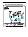
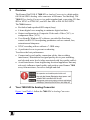
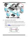
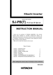
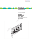
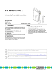
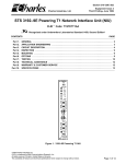
Kramer Electronics, Ltd. Preliminary USER MANUAL Model: 7408 SDI to Analog Converter Contents Contents 1 2 2.1 3 4 5 5.1 5.2 5.3 6 7 Introduction Getting Started Quick Start Overview Your 7408 SDI to Analog Converter Using Your 7408 SDI to Analog Converter Connecting Your 7408 SDI to Analog Converter Connecting to the 7408 via RS-232 Setting the DIP-Switches Technical Specifications Communication Protocol (Ver 0.1) 1 1 2 3 3 5 5 6 7 8 9 Figures Figure 1: 7408 SDI to Analog Converter Figure 2: Connecting a 7408 SDI to Analog Converter Figure 3: Crossed Cable RS-232 Connection Figure 4: Straight Cable RS-232 Connection with a Null-Modem Adapter 4 6 6 7 Tables Table 1: 7408 SDI to Analog Converter Table 2: Setting the DIP-switches Table 3: DIP-Switch Settings (AUTO, PAL, and NTSC) Table 4: Technical Specifications of the 7408 SDI to Analog Converter Table 5: Structure of the Protocol Table 6: Instruction Set for the 7408 4 7 8 8 9 9 i Introduction 1 Introduction Welcome to Kramer Electronics! Since 1981, Kramer Electronics has been providing a world of unique, creative, and affordable solutions to the vast range of problems that confront the video, audio, presentation, and broadcasting professional on a daily basis. In recent years, we have redesigned and upgraded most of our line, making the best even better! Our 1,000-plus different models now appear in 11 groups 1 that are clearly defined by function. Thank you for purchasing your Kramer DigiTOOLS 7408 SDI to Analog Converter, which is ideal for broadcast and production video studios, postproduction and duplication studios, and non-linear editing. The package includes the following items: • 7408 SDI to Analog Converter • Power supply • Null-modem adapter • Windows®-based Kramer control software • This user manual 2 2 Getting Started We recommend that you: • Unpack the equipment carefully and save the original box and packaging materials for possible future shipment • Review the contents of this user manual • Use Kramer high performance high-resolution cables 3 1 GROUP 1: Distribution Amplifiers; GROUP 2: Switchers and Matrix Switchers; GROUP 3: Control Systems; GROUP 4: Format/Standards Converters; GROUP 5: Range Extenders and Repeaters; GROUP 6: Specialty AV Products; GROUP 7: Scan Converters and Scalers; GROUP 8: Cables and Connectors; GROUP 9: Room Connectivity; GROUP 10: Accessories and Rack Adapters; GROUP 11: Sierra Products 2 Download up-to-date Kramer user manuals from our Web site at http://www.kramerelectronics.com 3 The complete list of Kramer cables is on our Web site at http://www.kramerelectronics.com 1 Getting Started 2.1 Quick Start This quick start chart summarizes the basic setup and operation steps. 2 KRAMER: SIMPLE CREATIVE TECHNOLOGY Overview 3 Overview The Kramer DigiTOOLS 7408 SDI to Analog Converter is a high quality, full 10-bit SDI to Analog video converter in a Kramer Tool housing. The 7408 SDI to Analog Converter is a multi-standard unit, converting 525-line SDI to NTSC or NTSC4.43, and 625-line SDI to PAL-B/D/G/H/I/N. The 7408 features: • Reclocked and equalized SDI output (loop) • 4 times digital over sampling to minimize digital artifacts • Output configuration to Composite Video and s-Video (Y/C), or component video (YUV) • User-friendly Windows PC software, provided for ProcAmp control via RS-232 for adjusting parameters such as contrast, hue, saturation and sharpness • NTSC encoding with or without a 7.5IRE setup • A perforated cover to prevent overheating To achieve the best performance: • Connect only good quality connection cables, thus avoiding interference, deterioration in signal quality due to poor matching, and elevated noise levels (often associated with low-quality cables) • Avoid interference from neighboring electrical appliances that may adversely influence signal quality and position your Kramer 7408 away from moisture, excessive sunlight and dust 4 Your 7408 SDI to Analog Converter Figure 1 and Table 1 define the 7408 SDI to Analog Converter: 3 NTSC PAL AUTO COMPONENT PROGRAM VBI PEDESTAL 4xOS Your 7408 SDI to Analog Converter Figure 1: 7408 SDI to Analog Converter Table 1: 7408 SDI to Analog Converter # 1 2 3 4 5 6 7 8 9 4 Feature 12V DC V / C BNC connector U / Y BNC connector Y / CV SDI OUT BNC Connector SDI IN BNC Connector ON LED RS-232 Port DIP-switches Function +12V DC connector for powering the unit Connect to: component video or composite video and/or s-Video acceptors (according to DIP-switch selection − see Table 3) Connects to the reclocked and equalized SDI acceptor Connects to the SDI source Illuminates when receiving power Connects to the PC or the remote controller To setup the unit (see section 5.2) KRAMER: SIMPLE CREATIVE TECHNOLOGY Using Your 7408 SDI to Analog Converter 5 Using Your 7408 SDI to Analog Converter You can use your 7408 SDI to Analog Converter to convert SDI video to professional analog video: composite video and s-Video, or component video (as the example in Figure 2 illustrates). 5.1 Connecting Your 7408 SDI to Analog Converter To connect the 7408, do the following 1: 1. Connect the SDI source (for example, a digital camera) to the SDI IN BNC connector. You may also connect the SDI OUT BNC connector to an SDI acceptor (such as an SDI monitor). 2. Connect the following: An s-video acceptor (such as an s-video monitor) to the C−Y output BNC connectors; and/or, A composite video acceptor, such as a composite video monitor to the CV output BNC connector; or, A component video acceptor, such as a VCR, to the YUV BNC connectors 3. Connect a PC (if required) to the RS-232 port (see section 5.2). 4. Set the DIP-switches, as section 5.2 describes. 5. Connect the 12V DC power adapter to the power socket and connect the adapter to the mains electricity. Warning: Do not cover the 7408 1 Switch OFF the power on each device before connecting it to your 7408. After connecting your 7408, switch on its power and then switch on the power on each device 5 Using Your 7408 SDI to Analog Converter Figure 2: Connecting a 7408 SDI to Analog Converter 5.2 Connecting to the 7408 via RS-232 You can connect to the unit via a crossed RS-232 connection, using for example, a PC. A crossed cable or null-modem is required as shown in method A and B respectively. If a shielded cable is used, connect the shield to pin 5. Method A (Figure 3)—Connect the RS-232 9-pin D-sub port on the unit via a crossed cable (only pin 2 to pin 3, pin 3 to pin 2, and pin 5 to pin 5 need be connected) to the RS-232 9-pin D-sub port on the PC. Note: There is no need to connect any other pins. Figure 3: Crossed Cable RS-232 Connection 6 KRAMER: SIMPLE CREATIVE TECHNOLOGY Using Your 7408 SDI to Analog Converter Hardware flow control is not required for this unit. In the rare case where a controller requires hardware flow control, short pin 1 to 7 and 8, and pin 4 to 6 on the controller side. Method B (Figure 4)—Connect the RS-232 9-pin D-sub port on the unit via a straight (flat) cable to the null-modem adapter, and connect the nullmodem adapter to the RS-232 9-pin D-sub port on the PC. The straight cable usually contains all nine wires for a full connection of the D-sub connector. Because the null-modem adapter (which already includes the flow control jumpering described in Method A above) only requires pins 2, 3 and 5 to be connected, you are free to decide whether to connect only these 3 pins or all 9 pins. Figure 4: Straight Cable RS-232 Connection with a Null-Modem Adapter 5.3 Setting the DIP-Switches Configure the 7408 unit by setting the DIP-switches, as Table 2 defines: Table 2: Setting the DIP-switches DIPS Function 1 PROGRAM Description ON for upgrading firmware; otherwise OFF 2 3 VBI PEDESTAL 1 ON to enable Vertical Interval Blanking; OFF to disable ON for pedestal (7.5 IRE offset selection for NTSC); OFF for no pedestal 4 4XOS 2 ON to enable oversampling 3; OFF to disable oversampling 5 NTSC ON for NTSC 3.58 (see Table 3) 6 PAL ON for PAL (see Table 3) 7 AUTO ON for multi-standard; OFF for user selected (fixed) standard (see Table 3) 8 COMPONENT ON for component video; OFF for composite video and/or s-video 1 NTSC offsets the black level within the active video signal by 7.5 IRE when selected 2 4xOS is 4 x Oversample 3 When this method is used, the noise figure is improved 7 Technical Specifications Table 3: DIP-Switch Settings (AUTO, PAL, and NTSC) 6 AUTO OFF PAL OFF NTSC OFF NTSC 4.43 OFF OFF OFF ON 7408 Output Standard OFF ON NTSC 3.58 ON OFF PAL-B ON OFF ON OFF PAL-N PAL-N for 625 line SDI input; NTSC 4.43 for 525 line SDI input ON OFF ON PAL-N for 625 line SDI input; NTSC 3.58 for 525 line SDI input ON ON OFF PAL-B for 625 line SDI input; NTSC 4.43 for 525 line SDI input ON ON ON PAL-B for 625 line SDI input; NTSC 3.58 for 525 line SDI input Technical Specifications Table 4 includes the technical specifications: Table 4: Technical Specifications 1 of the 7408 SDI to Analog Converter INPUT: 1 SDI: SMPTE-259M, ITU-R BT.601 on a BNC connector OUTPUTS: 1 reclocked SDI: SMPTE-259M, ITU-R BT.601 on a BNC connector; 1 composite video: 1Vpp/75Ω on a BNC connector; 1 s-Video: 1Vpp, 0.3Vpp/75Ω on two BNC connectors; 1 component video (Y, U and V) on three BNC connectors BANDWIDTH (-3dB): 5.7MHz DIFF. GAIN: <1% DIFF. PHASE: <1Deg K-FACTOR: 0.5% S/N RATIO: DIGITAL RESOLUTION: >70dB (flat field) 10 bit LUMA NON-LINEARITY: 0.9% CHROMA/LUMA DELAY: <15nsec POWER SOURCE: 12V DC, 320mA DIMENSIONS: WEIGHT: 12cm x 7.5cm x 2.5cm (4.7" x 2.95" x 0.98") W, D, H 0.3kg (0.66lbs) ACCESSORIES: Power supply, null-modem adapter OPTIONS: RK-3T 19" rack adapter 1 Specifications are subject to change without notice 8 KRAMER: SIMPLE CREATIVE TECHNOLOGY Communication Protocol (Ver 0.1) 7 Communication Protocol (Ver 0.1) RS-232 communication between the 7408 and the PC is done using the following protocol. The protocol uses four bytes of information, and data is at 9600 baud, no parity, 8 data bits and 1 stop bit. The controller and machine should be connected via a null-modem connection, that is, if using a DB-9 port, connect as follows: Connect pin 5 of the PC to pin 5 of the machine Cross pins 2 and 3, i.e., connect pin 2 of the PC to pin 3 of the machine, and connect pin 3 of the PC to pin 2 of the machine On the PC side, short pins 4 and 6 On the PC side, short pins 1, 7 and 8 Table 5: Structure of the Protocol MSB LSB INSTRUCTION 0 7 1st byte TO PC 6 I5 5 I4 4 I3 3 1 7 2nd byte D6 6 D5 5 D4 4 D3 3 1 7 3rd byte E6 6 E5 5 E4 4 E3 3 1 7 4th byte 1 E7 6 0 4 1 3 I2 2 I1 1 I0 0 D2 2 D1 1 D0 0 E2 2 E1 1 E0 0 1 2 1 1 0 0 DATA EXTENDED DATA MSB’s D7 5 ADDR Note that the MSB’s of the DATA (D7) and the EXTENDED DATA (E7) are in the fourth byte. Terminology: TO PC is the “DESTINATION BIT” I4..I0 is the “INSTRUCTION” D7..D0 is the “DATA” E7..E0 is the “EXTENDED DATA” The destination bit, TO PC, is 0 when sending from the PC to the machine, or 1 when sending from the machine to the PC. Table 6: Instruction Set for the 7408 INSTRUCTION Dec Hex 0 3 4 5 6 7 8 10 11 12 13 14 15 16 30 31 57 61 0 3 4 5 6 7 8 A B C D E F 10 1E 1F 39 3D Reset Store machine settings Recall machine settings Set Video Parameter Request Video Parameter Read video encoder data Write video encoder data Write EEPROM data Read EEPROM data Write I²C Read I²C Read video standard Is setup defined? Error Lock Front Panel Request Bar Enable “Power-down save” Identify machine I7 I6 I5 I4 I3 I2 I1 I0 0 0 0 0 0 0 0 0 0 0 0 0 0 0 0 0 0 0 0 0 0 0 0 0 0 0 0 0 0 0 0 0 0 0 0 0 0 0 0 0 0 0 0 0 0 0 0 0 0 0 0 0 1 1 0 0 0 0 0 0 0 0 0 0 0 0 0 1 1 1 1 1 0 0 0 0 0 0 1 1 1 1 1 1 1 0 1 1 1 1 0 0 1 1 1 1 0 0 0 1 1 1 1 0 1 1 0 1 0 1 0 0 1 1 0 1 1 0 0 1 1 0 1 1 0 0 0 1 0 1 0 1 0 0 1 0 1 0 1 0 0 1 1 1 1 Note that the MSB’s of the DATA (D7) and the EXTENDED DATA (E7) are in the fourth byte 9 Communication Protocol (Ver 0.1) DESCRIPTION OF INSTRUCTIONS INSTRUCTION 0 – RESET DATA=0: initialize the machine. When the machine is initialized, it will send the RESET code (DATA = 0). If the machine receives this code, it will reset to its “power-up” state. DATA=1: configure the machine to its factory default state. When the machine receives this code, all programmable parameters will be reset to their factory-default values. EXTENDED DATA - set as 0. INSTRUCTION 3 – STORE MACHINE SETTINGS DATA = setup# (1 to 10) where present values of machine settings are saved. EXTENDED DATA - set as 0. - When the machine receives this instruction, its present settings (video parameters) are saved in non-volatile memory. The machine replies by sending the same 4 bytes (except for the Destination Bit) back to the PC. - When the user saves the machine settings using the front-panel buttons, then this instruction is sent to the PC. INSTRUCTION 4 – RECALL MACHINE SETTINGS DATA = setup# (1 to 10) of machine settings which are to recalled. EXTENDED DATA - set as 0. - When the machine receives this instruction, it recalls the settings which were previously saved in the setup#. The machine replies by sending the same 4 bytes (except for the Destination Bit) back to the PC. - When the user recalls a setup using the front-panel buttons, then this instruction is sent to the PC. INSTRUCTION 5dec – SET VIDEO PARAMETER DATA = Video parameter #, defined as follows: 1 = Brightness 2 = Contrast 3 = Hue 4 = Sharpness 5 = Colour saturation 6 = R-Y saturation 7 = B-Y saturation EXTENDED DATA - value for selected video parameter . - When the machine receives this instruction, then, if valid, the selected video parameter is set and the machine replies by sending the same 4 bytes (except for the Destination Bit) back to the PC. - When the user changes video parameters using the front-panel buttons, then this instruction is sent to the PC. Note that the video parameter values range from 0 (minimum) up to 255dec (maximum), and do not necessarily correspond with the number displayed on the panel of the 7408. If a value outside the legal range of a particular parameter is sent, the error code will be returned. INSTRUCTION 6 – REQUEST VIDEO PARAMETER For sending to machine, DATA = VIDEO parameter #, defined as in INSTRUCTION 5; EXTENDED DATA=0; When replying DATA = VIDEO parameter #, defined as in INSTRUCTION 5; EXTENDED DATA- value for selected VIDEO parameter. INSTRUCTION 7 – READ VIDEO ENCODER DATA For sending to machine, DATA = VIDEO ENCODER sub-address which is to be read. When replying:- DATA = VIDEO ENCODER sub-address; EXTENDED DATA = requested data. The PC sends this instruction to the machine. The machine replies by sending back the data assigned to this sub-address. INSTRUCTION 8 – WRITE VIDEO ENCODER DATA DATA = VIDEO ENCODER sub-address; EXTENDED DATA = data to be written to this sub-address. The PC sends data directly to the encoder. The machine implements this new value, and replies by sending the same 4 bytes (except for the Destination Bit) back to the PC. CAUTION – this function was designated for development and testing purposes. Improper use of this function may cause erratic behaviour of the machine. INSTRUCTION 10dec – WRITE EEPROM DATA DATA = EEPROM sub-address; EXTENDED DATA = data to be written to this sub-address. The PC sends data directly to the EEPROM. The EEPROM stores this new value, and replies by sending the same data back to the PC. 10 KRAMER: SIMPLE CREATIVE TECHNOLOGY Communication Protocol (Ver 0.1) CAUTION – this function was designated for development and testing purposes. Improper use of this function may cause erratic behaviour of the machine. INSTRUCTION 11dec – READ EEPROM DATA For sending to machine, DATA = EEPROM sub-address which is to be read. When replying:- DATA = EEPROM sub-address; EXTENDED DATA = requested data. The PC sends this instruction to the machine. The machine replies by sending back the data stored in this sub-address. INSTRUCTION 12dec – WRITE I²C DATA = I²C sub-address; EXTENDED DATA = data to be written to this sub-address. The PC sends I²C data (to the I²C address which was last accessed via INSTRUCTION 13). The machine replies by sending the same data back to the PC. CAUTION – this function was designated for development and testing purposes. Improper use of this function may cause erratic behavior of the machine. INSTRUCTION 13dec – READ I²C For sending to machine, DATA = I²C address; EXTENDED DATA = sub-address. When replying:- DATA = sub-address; EXTENDED DATA = data read. The PC sends this instruction to the machine. The machine replies by sending back the data of this address and sub-address. INSTRUCTION 14dec – READ VIDEO STANDARD For sending to machine, set DATA = EXTENDED DATA = 0. When replying:- DATA = 0; EXTENDED DATA = VIDEO STANDARD. The PC sends this instruction to the machine. The machine replies by sending back the video standard, defined as follows: 0 = NTSC4.43 1 = NTSC 2 = PAL 3 = PAL-N 64dec (40hex)= Invalid or no input detected Note that when the DIP-switches are set for a fixed standard, the 7408 will reply by sending the code for the fixed standard. INSTRUCTION 16dec – ERROR If the machine receives an invalid instruction, it replies by sending this error code. INSTRUCTION 30dec – LOCK FRONT PANEL DATA = 0: panel is unlocked. DATA = 1: panel is locked. EXTENDED DATA - set as 0. - When the machine receives this instruction, it will lock or unlock the panel for control via the front-panel pushbutton switches (RS-232 control is unaffected). - When the user changes the lock status using the front-panel button, then this instruction is sent to the PC. INSTRUCTION 31dec – REQUEST BAR For sending DATA = EXTENDED DATA = 0 When replying EXTENDED DATA = 1, if Bar INSTRUCTION 57dec – ENABLE “POWER-DOWN SAVE” DATA = 0 disables power-down saving; DATA = 1 enables saving. EXTENDED DATA - set to 0. The PC sends this instruction to the machine. The power-down option is enabled or disabled according to the value of DATA. If the power-down option is enabled, then the machine will “remember” its state before being turned off, and revert to this state when turned on again. Note that whenever the machine is turned on, the power-down save option is enabled. INSTRUCTION 61dec – IDENTIFY MACHINE For sending, DATA = 1 to request machine name; DATA = 3 to request software version number. EXTENDED DATA - set to 0. The PC sends this instruction to the machine. The machine relies as follows: If the machine name is requested, the machine replies with DATA = 40 (hex), and EXTENDED DATA = 45 (hex). If the software version is requested, the machine replies with DATA as the version number before the decimal point, and EXTENDED DATA is the value following the decimal point. For example, for version 3.4, the machine replies with DATA = 03 (hex), and EXTENDED DATA = 04 (hex). 11 LIMITED WARRANTY Kramer Electronics (hereafter Kramer) warrants this product free from defects in material and workmanship under the following terms. HOW LONG IS THE WARRANTY Labor and parts are warranted for three years from the date of the first customer purchase. WHO IS PROTECTED? Only the first purchase customer may enforce this warranty. WHAT IS COVERED AND WHAT IS NOT COVERED Except as below, this warranty covers all defects in material or workmanship in this product. The following are not covered by the warranty: 1. Any product which is not distributed by Kramer, or which is not purchased from an authorized Kramer dealer. If you are uncertain as to whether a dealer is authorized, please contact Kramer at one of the agents listed in the Web site www.kramerelectronics.com. 2. Any product, on which the serial number has been defaced, modified or removed, or on which the WARRANTY VOID IF TAMPERED sticker has been torn, reattached, removed or otherwise interfered with. 3. Damage, deterioration or malfunction resulting from: i) Accident, misuse, abuse, neglect, fire, water, lightning or other acts of nature ii) Product modification, or failure to follow instructions supplied with the product iii) Repair or attempted repair by anyone not authorized by Kramer iv) Any shipment of the product (claims must be presented to the carrier) v) Removal or installation of the product vi) Any other cause, which does not relate to a product defect vii) Cartons, equipment enclosures, cables or accessories used in conjunction with the product WHAT WE WILL PAY FOR AND WHAT WE WILL NOT PAY FOR We will pay labor and material expenses for covered items. We will not pay for the following: 1. Removal or installations charges. 2. Costs of initial technical adjustments (set-up), including adjustment of user controls or programming. These costs are the responsibility of the Kramer dealer from whom the product was purchased. 3. Shipping charges. HOW YOU CAN GET WARRANTY SERVICE 1. To obtain service on you product, you must take or ship it prepaid to any authorized Kramer service center. 2. Whenever warranty service is required, the original dated invoice (or a copy) must be presented as proof of warranty coverage, and should be included in any shipment of the product. Please also include in any mailing a contact name, company, address, and a description of the problem(s). 3. For the name of the nearest Kramer authorized service center, consult your authorized dealer. LIMITATION OF IMPLIED WARRANTIES All implied warranties, including warranties of merchantability and fitness for a particular purpose, are limited in duration to the length of this warranty. EXCLUSION OF DAMAGES The liability of Kramer for any effective products is limited to the repair or replacement of the product at our option. Kramer shall not be liable for: 1. Damage to other property caused by defects in this product, damages based upon inconvenience, loss of use of the product, loss of time, commercial loss; or: 2. Any other damages, whether incidental, consequential or otherwise. Some countries may not allow limitations on how long an implied warranty lasts and/or do not allow the exclusion or limitation of incidental or consequential damages, so the above limitations and exclusions may not apply to you. This warranty gives you specific legal rights, and you may also have other rights, which vary from place to place. NOTE: All products returned to Kramer for service must have prior approval. This may be obtained from your dealer. This equipment has been tested to determine compliance with the requirements of: EN-50081: EN-50082: CFR-47: "Electromagnetic compatibility (EMC); generic emission standard. Part 1: Residential, commercial and light industry" "Electromagnetic compatibility (EMC) generic immunity standard. Part 1: Residential, commercial and light industry environment". FCC* Rules and Regulations: Part 15: “Radio frequency devices Subpart B Unintentional radiators” CAUTION! Servicing the machines can only be done by an authorized Kramer technician. Any user who makes changes or modifications to the unit without the expressed approval of the manufacturer will void user authority to operate the equipment. Use the supplied DC power supply to feed power to the machine. Please use recommended interconnection cables to connect the machine to other components. * FCC and CE approved using STP cable (for twisted pair products) 12 KRAMER: SIMPLE CREATIVE TECHNOLOGY For the latest information on our products and a list of Kramer distributors, visit our Web site: www.kramerelectronics.com where updates to this user manual may be found. We welcome your questions, comments and feedback. Safety Warning: Disconnect the unit from the power supply before opening/servicing. Caution Kramer Electronics, Ltd. Web site: www.kramerelectronics.com E-mail: [email protected] P/N: 2900-000019 REV 2