1
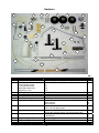
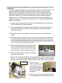
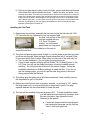
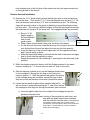
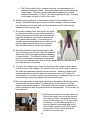
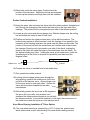
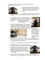
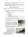
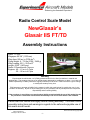
“Enhancing the Homebuilt Experience”
Radio Control Scale Model
NewGlasair’s
Glasair IIS FT/TD
Assembly Instructions
Scale: 1= 4.62
Wingspan: 60 3/8” (1533 mm)
Wing Area: 589 sq. in (3798 dm2)
Flying Weight: 6 – 7.5 lbs (2700 – 3400 g)
Wing Loading: 23.5 – 29.3 oz/ft2
Length: 55.25” (1403 mm)
Radio: 5 Channels with 7 servos
Engines: .46 – .61 cu in 2 Cycle
.50 – .90 cu in 4 Cycle
Warranty
Experimental Aircraft Models, LLC (EAM) guarantees this kit to be free from defects in material and
workmanship. The warranty does not cover individual parts damaged by modification or abuse. In no case will
EAM’s responsibility or liability exceed the original purchase price of the kit. EAM reserves the right to change
or modify this warranty at any time.
EAM assumes or accepts no liability for the manner in which this model aircraft is used by the user, in any
condition of assembly. By the act of purchasing this kit, the purchaser and any subsequent user accepts full
responsibility and all resulting liability.
If the purchaser is not willing to accept the above liability associated with the use of this model aircraft,
the purchaser is advised to return this kit immediately to the source from where it was obtained.
Please read this manual thoroughly before starting assembly. It includes critical
assembly
instructions and warnings in regards to the safe and enjoyable use of
Kit Contents
this scale aircraft model.
Experimental Aircraft Models, LLC
33924 Cotswold Rd.
Farmington Hills, MI 48335
Entire Document © Copyright 2003
-1-
About Your Model : You have purchased one of a limited production run of
Glasair IIS RC model kits in the world. You have a very unique model of an
Experimental aircraft.
In the United States, ‘Experimental Aircraft’ are aircraft that are 51% or more built by an individual (usually
at home) and fly under an FAA issued “Flight Permit”, rather than “Certification”. During the past 20 years
the most advanced designs in civil aviation aircraft have come from the ‘Homebuilt’ arena, where without
the burden of certification expense and manufacturers liability insurance, aircraft of amazing performance
and safety could be designed and offered to the public.
In our mission to support the homebuilder with a scale model of an aircraft project that may have
consumed hundreds/thousands of hours to complete, we have brought together full-scale aircraft kit
airframe manufacturers with a state-of-the-art world class ARF (Almost Ready to Fly) model
manufacturer. Our intent is to provide as scale a model as possible that is as ARF as possible - within the
confines of limited production run sizes and knowledge that a builder will likely customize to match their
own aircraft. In that sense, this product caters more to the full scale builders, and scale modelers, than it
does ‘out of the box’ flyers.
Some interesting details about the production of this model; We control the entire process of the model
construction, starting with the direct import of balsa logs from Ecuador, to hand carving the fiberglass
plugs and lay-up of the fiberglass components. The canopy molds are also hand carved and the vacuum
forming is all done ‘in-house’.
Just as the homebuilder customizes their personal aircraft, we have offered the model in pure white, so
that you may do the same. We also include multiple landing gear configurations in the kit, so that you
may choose between the full-scale configurations offered by the airframe kit manufacturer. For those
unfamiliar with the FT/TD designation, the “TD” is the Conventional gear (TailDragger) version and the FT
is the Fixed Tricycle gear version. Otherwise the airframes are identical. We use a formed aluminum
main gear secured to the fuselage for the conventional version, and reverse the same gear and install it
on the wings for the tricycle version.
Please note that we use aircraft terminology in our instructions. Specifically ‘Port’ is left and ‘Starboard’ is
Right, and ‘Forward’ is to the front and Aft is to the rear. No matter how you may have the model turned
Port is always the left side of the aircraft as the pilot sits in the cockpit facing forward. Thus if you are
working on the model upside down with the tail facing towards you while installing servos, putting
something on the Port side eliminates the confusion that ‘left’ side might result in.
A final point: Because the model is so special and the volumes (by model standards) so low, we need
your help. We have tried our absolute best to get everything right the first time. If there is something
during the construction and flying of the model that you feel could be done more easily or better, we’d like
to know. This is how it’s done in the full size experimental aircraft world, and we want to be sure that the
same spirit is carried on in smaller scale. Builders are continually finding ways to improve the full size
aircraft, and there is no reason why modelers should not have the same ability to contribute to a better
product.
Please feel free to e-mail us with kit comments at: [email protected]
We sincerely appreciate your vote of confidence in purchasing our rendition of NewGlasair’s Glasair IIS
and truly wish you the best of enjoyment.
Cleve L. Lee
Managing Director
Experimental Aircraft Models, LLC
-2-
A note about the covering: Your Glasair SII is covered in White ‘Oracover’ – commonly
known as ‘Ultracote’ in the U.S. This is a high quality material, but through temperature changes
during shipping, the model may show wrinkles. This is normal. This symptom is also more
visible in that your model is fully balsa sheeted. The covering can easily be tightened by the
application of heat from a hair dryer/heat gun or hot iron. If using an iron, a piece of lightweight
cotton (e.g. sheeting) placed between the iron and the covering helps to even the heating.
Pressing lightly will transfer the heat to the covering, shrinking the material. Making a few pin
pricks in the area and rubbing the hot area with a cloth further helps remove the wrinkles.
Airframe Components
4
13
3
9
1
5
2
12
10
7
8
Item
1
2
3
4
5
6
7
8
9
10
11
12
13
Description
Port (Left) Wing
Fuselage
Canopy
Stabilizer & Elevators
Rudder
Wing bolt protective strip (not shown)
Motor mount box top & corner brace (brace shown)
Wing Joiner
Starboard Wing
Fiberglass Cowl
Main gear wheel pants (not shown)
Nose gear wheel pant w/fairing
Wing Belly cover
-3-
Hardware
1
3
2
5
6
7
9
22
20
19
4
30
8
23
32
10
21
25
11
12
24
27
15
18
26
14
16
31
17
28
13
Qty.
Item
1
2
Description
3
4
5
6
7
Control horns
Control horn screws
Cowl mounting screws
Canopy attach screws
Wheel pant attachment
Wing Servo Cover
Landing Gear attach screw
Axle shafts w/Lock Nuts
Main gear wheels
Nose wheel
Engine Mount to Firewall bolts
8
Motor to Mount bolts
9
Nose gear mount
10
Nose gear mounting bolts
11
12
Wing mounting bolts
Wing mounting nuts
Item
Detail
(1) Rudder (2) Elevator (2) Ailerons (2) Flaps
(14) #2 x3/8” Washer Head sheet metal screw
(5)
(5)
(10)
(16)
M4 x 15 Pan head sheet metal screw
Spring steel axle shafts 5/32 x 1 ½” (4x40mm)
2.8” dia.
2.7” dia
8-32 x 1 ¼ socket head machine screw (U.S. Pack)
8-32 Locknuts
#8 flat washers
6-32 x 1 ¼” pan head machine screw
6-32 Lock nuts (Nylon insert)
A) Nylon two piece 5/32 (4mm) i.d. pivot hole
B) Pivot arm w/collar insert & 4-40 socket head screw
4-40 x ¾” cap head machine screws
4-40 blind nut
¼-20 x 1 ½” Nylon
¼-20 Blind “T” nuts
Description
Detail
-4-
7
50
6
2
2
1
4
4
4
4
4
2
1
4
4
2
2
13
14
Pushrods.
Elevators and Rudder
Nylon Clevis Ends
15
Nylon Quick Link
16
Pushrod Wire
17
18
19
20
Tie wraps
Fuel Tank
Wire nose gear
Main Gear Wheel Pants
Retainers
Nose Wheelpant Retainer
Wheel Retainers
Tail wheel steering
Tail wheel
Nose wheel pant ply
Clevis Retainers
Engine mount
Nylon Guide Tube
Motor mount template
Servo mounting blocks
Servo Stopper/Connector
Main gear (Conventional)
Main gear (Tricycle)
Conventional Gear Hardware
21
22
23
24
25
26
27
28
29
30
31
32
33
34
Wood 15 3/4” (400 mm)
2
(1) Rudder (2) Elevators (1) Throttle Servo
(1) Steering Servo (2) Flaps (2) Ailerons
(1) Throttle arm (1) Steering arm (2) Ail (2) Flaps
(1) Rudder (1) Elevator
(4) .078 dia (2 mm) 6 ¾” (17 cm) – Ail. & Flaps
(1) .047 dia (1.2 mm) 17”( 43 cm) Throttle wire
(1) 18” (46 cm) 2 mm steering wire
(1) Nylon slip tube for 2 mm wire 17” (450mm)
12” tie wraps to secure radio and tank
380 CC
Spring steel – 5/32” (4 mm)
Sullivan stamped steel retainers
#2 Sheet metal screws
Flat Nylon keeper
5/32 ID. Collars, w/ 4-40 Cap Head screws
Tailwheel steering bracket with mounting screws
9
Silicon bands
Glass reinforced Nylon
2.7mm id. Guide tube to install rods 17”(450mm)
OS .40 & OS .60 (not pictured)
¾ x ¾ x 3/8” wood blocks
Throttle wire attachment to servo
Formed Aluminum
Formed wire (not shown)
Bolts w/blind nuts (not shown)
Building the Wing
Sequence of events in this section:
• Installing Ailerons and Flap hinges
• Opening servo cover slots, wire and bolt holes in covering
• Threading servo wire extensions and installing servos
• Installing control arms, horns and pushrods
• Permanently assembling the wing halves
• Test fitting the wing
Additional components you may need from the hobby store:
CA Adhesive (Thin)
CA Adhesive (Medium)
(2) 12” Servo wire extensions
(2) “Y” Servo wire harnesses
(4) Extended length servo arms to fit your brand of servo (Optional)
-5-
8
4
1
1
4
5
7
1
1
2
18
1 pr
2
1
8
1
1
L&R
6 ea
Installing Ailerons and Flap Hinges
The control surfaces on the wings and stabilizers are not yet permanently attached.
We have pre-cut and positioned the ‘CA’ hinges for you. In this step you will be
removing the flaps and aileron control surfaces from the wings, prepare them for
attachment, and permanently re-installing them on the wings.
1) Pull the ailerons and flaps
away from the wing.
2) Trim away the Oracover from
around the hinge slots on both
the wings and the control
surfaces. Our favorite method
is to use an old soldering iron
with a point on the end. This
seals the Oracover to the wood at the same time as it melts back the covering
from the slot. Otherwise a razor knife (or No. 11 scalpel) can be used to trim
away the material. The objective is to be sure the adhesive can wick into the slot.
You don’t want an edge of film sitting against the hinge, which may prevent the
adhesive from flowing into the slot.
3) Drill a small (1/16” or 1.5mm) hole in
the center of each slot to help ‘wick’
the adhesive onto the hinge in the
next step.
4) Insert the CA hinges halfway into the
slots on the control surfaces and place
about 4 –6 drops of CA into the slot on
both sides of the hinge material.
5) Position the control surfaces up to the wing, inserting the now bonded hinges into
the slots in the wing. Position both the flap and the aileron in the desired
position, spacing as appropriate to make the distances between surfaces and
wing equal. Apply a few drops of Thin CA to the bottom of the flap hinges, and
then (after a few seconds) rotate the flap downward and apply adhesive to the
top of the hinge.
6) Finish the installation on the opposite wing.
7) Pull on the control surfaces to test their strength.
-6-
Opening wire, servo slots and bolt holes in covering
The Oracover must be removed in certain areas to allow mounting of the wing,
clearance for servo pushrod operation and exiting of servo wires from the wing into
the fuselage. We will also prepare the servo covers for mounting of the servos.
1) Referencing the picture, use either a sharp
pointed razor knife or hot soldering iron and
open the two ¼” (6mm) wing mounting bolt
holes (top and bottom) and the two ½” wire
exit hole located on the top of the wing.
(The servo wires enter into the cabin space
from the top side of the wing.) If using the
razor knife, you’ll get better results if you
cut on the downward stroke – pushing the
covering against the underlying wood for
support as you cut.
2) Locate the servo bay covers on the bottom of each wing. Remove one at a time,
mark the bottom side of the cover and inside the servo bay with a letter or
number to maintain their relationship.
a. For future reference, note that
the slots for the aileron servos
are ‘outboard’ from the plane’s
center line, and are left and
right (opposite) to each other.
This is because the ailerons
operate in opposite directions.
b. The flap servo covers both
have the slots to the same
side of the servo cover
centerline – because the flaps both operate in the same direction.
3) Trim the slot opening of each servo cover with a sharp razor knife. (Don’t use
the soldering iron trick, as it will show the melted edge where it would be visible
from the bottom side of the plane.)
4) With the covers in place, drill a 1/16” (1.5mm) hole
at each corner. Install #2 x3/8” washer head
screws, then remove and place a few drops of Thin
CA into the holes to strengthen the threads.
-7-
Threading Servo Wire Extensions and Installing Servos
For ease of serviceability we secure the servos directly to the underside of the servo
covers, mounting them to wood blocks. Verify that the servo arms are electrically
neutral and you are using the length arm you intend to use. (Refer to your Radio
owners manual for techniques for centering the servo arm.)
1) Install the rubber pads and eyelets into the servo mounting lugs (supplied by
servo mfg.)
2) Position a servo on the back side of a servo cover, with the arm projecting at 90
degrees through the slot, and the face of the arm parallel to the slot.
3) Test fit two wood blocks (supplied) under the servo mounting lugs. Double check
position of the servo arm in the slot, and allow room for compression of the
rubber pads, if necessary, when the mounting screws are tightened.
4) Bond the wood blocks to the servo cover using at least a medium thickness CA
adhesive, or better yet, epoxy.
5) Test fit the cover with the blocks & servo into
the wing. In some cases the cover support
in the wing may need to be cut away in the
area of the block.
6) Before securing the servo, replace (if
necessary) the output arm with an arm long
enough to allow clearance of the pushrod
when operated to extreme positions.
Alternatively, if you are unable to locate
longer servo output arms, you can widen the
slot to allow room for the rod keeper,
(installed in the next section) which would otherwise interfere with the top side of
the cover. This approach may require bending the push rod so that it enters the
slot slightly more vertically - Like this
instead of
7) Repeat the above process for all four wing servos. Again, note how the Flap
servos both face in the same direction, while the aileron servos lay in opposite
directions.
8) Plug a 12” servo cable extension on to both of the Aileron servo cables. Use a
piece of heat shrink tubing or electrical tape to keep the connection secure.
9) Using the pre-installed monofilament pull string, draw the aileron servo cables
through the wing just up to the flap servo bay.
a. If the cord is missing or has been pulled through by accident, the plastic
pushrod guide tubes or metal pushrods in the kit make great ‘snakes’.
Insert into the root rib routing hole, push through to the servo bay and
attach the servo cable to the wire/tube using electrical tape.
-8-
10) Secure the end of the flap servo cable behind the aileron connector (so they both
fit through the hole) temporarily with tape, and pull the ‘train’ through to the root
rib of the wing. Remove pull string.
Pull the servo wires out through the hole in the top
of the wing. Separate the aileron and flap servo
wires, and clearly label each for later connection
to the receiver.
Pull String (shown enlarged)
11) Repeat the servo
installation process for the other wing.
12) Plug the servos into the receiver and test their operation
to be sure wire connections inside the wing remained
tight.
Installing control arms, horns and pushrods
Now that the servos are installed and respond to the radio, it’s time to make them move
the control surfaces. Nylon control horns will be fastened to the ailerons and flaps, and
pre-sized wire pushrods will be bent and cut to final length. Nylon clevises will then be
threaded on to the ends of the pushrods and connected to the control horns.
1) Plug an aileron servo into the receiver
and turn the transmitter ‘on’ and set the
trim to center.
2) With the servo cover in place, but not
screwed down, double check that the
servo arm exits the slot perpendicular to
the cover.
3) Position a nylon control horn on the aileron so that it is offset to one side and
lines up with one side of the servo arm, not the centerline. Secure the control
horn to the aileron with #2 x 3/8” screws. There are plywood hard points in the
aileron into which you can screw directly. (If you prefer you can use the nylon
backing plates, which will require longer screws.)
4) Retrieve a 6 ¾ ” (170mm) pushrod, & thread a black rod clevis at least 20 half
turns, and slip a silicon clevis retainer on to the assembly.
5) Temporarily attach the clevis to the control horn in a middle hole, and determine
whether your servo arm is long enough to have a straight pushrod, or if the
pushrod will require a bend to facilitate full travel of the servo arm without hitting
the ends of the slot in the cover. (Seen note in step 6 above)
6) Bend the arm as required so that it will align with a hole on the servo arm (when
centered), and then place the rod so that it passes over the desired hole in the
servo arm. Mark the location of the hole on the wire and subtract 1/16” (1.5mm)
-9-
for a bend allowance. Carefully bend a right angle, in the direction opposite the
offset of the control horn, so that it can enter the servo arm.
7) Cut off and deburr the end of the wire so that the right angle short leg measures
at least 3/16” from the inside of the bend. The servo arm may require drilling of
the hole to accept the pushrod wire diameter.
8) Secure the pushrod to the servo using a nylon Quick Link.
Permanently Assemble the Wing Halves
The two wing halves are joined using the plywood wing joiner and 30 minute epoxy.
1) Locate the Wing Joiner – this piece strengthens the joint between the wings and
sets the wing dihedral.
2) Test fit the Joiner into both wing halves and slide the wings together to be sure
both root ribs meet at the center. Mark the center of the Joiner as a reference
mark. Sand as necessary to get a smooth close fit.
3) Separate the wings and using a scrap piece of wood, Popsicle stick or tongue
depressor, apply 30 minute epoxy to the inside of the Joiner box on both wings
and one end of the Joiner. Slip the joiner into the wing.
4) Coat the root ribs on both wings and the remaining portion of the Joiner, and slip
the wings together.
5) Wipe away the excess epoxy (Isopropyl alcohol does a good job) and clamp and
tape the leading and trailing edges together to
prevent twisting while drying. A small clamp on
the leading edge root rib tabs is also helpful.
(Consider protecting the clamp with cello packing
tape.)
6) Set aside to dry in a location away from the dog
and cat and some place flat so that you will not
induce a twist. Support one wing so that the root
ribs are kept fully pressed against each other.
This guarantees the correct dihedral.
Test Mount Wing to Fuselage
1) Locate the two ¼-20 half high Blind nuts supplied in the
US pack. With the fuselage upside down, place them
beneath the plywood supporting the trailing edge, “T” side
up, and pull them into place using the full thead ¼-20
UNC bolt and washer supplied in the U.S. Pack.
2) Insert the tabs at the leading edge of the wing into the slot
- 10 -
on the bulkhead where the leading edge fits, and lower the trailing edge against
the fuselage.
3) Insert two ¼ - 20 Nylon Finger Wing Mounting Bolts through the wing holes and
open as appropriate to allow easy insertion of the bolts. Nylon bolts are easy to
cross thread, so use care. Remove the bolts for the next step.
4) Retrieve the wing Belly Cover and insert the doweled ends into the bulkhead at
the leading edge of the wing. Lower the trailing edge into place. You will need to
trim away the Oracover from over the wing bolt holes with a razor knife. Open up
the holes to allow passage of the head for the Finger Bolts supplied.
5) Insert the wing bolts, making sure all holes line up. The bolts will sit beneath the
surface of the cover against a plywood shelf.
6) When all fits properly you may cut the bolts to a desired length (Best way to do this is
to thread a nut onto the threads before cutting so that the removal of the nut cleans up the
threads.)
7) Remove the wing for the next steps.
Installing the Tricycle Main Gear
If you are choosing to build the FT version of the aircraft, now is a good time to
install the main aluminum landing gear on the wing. Skip this section if you are installing
the conventional gear.
1) Retrieve the aluminum landing gear and mark the center line between the two
legs. The gear will be fitting against the bottom
of the wing, and as such needs a slight bend in
the middle to match the wing dihedral. (We do not
pre-bend it because it is used without the bend in the
conventional gear version.) Bend the gear at the
center mark so as to move the legs apart.
Check the fit of the bend against the center
section of the wing. Bend the short legs back to
vertical as required so that the axles, when
place through the holes at the very ends, will be
square with the ground.
2) In the U.S. pack we have supplied a set of DuBro 5/32” axles, improving upon
most manufacturers use of threaded bolts as axles. Two minor modifications are
required to enable using them:
a. Cut them to length. Cut off approximately 3/8” (9.5 mm) so that the axle
portion measures 1 ½” to 1 5/8” (38 – 41mm)
b. Enlarge the main gear bolt holes (those closest to the ends of the
aluminum gear). Using the existing hole as a pilot hole, drill them out to
5/16”. This will allow insertion of the threaded portion of the axle into the
landing gear.
- 11 -
c. Install the axles onto the main gear and secure with the supplied locknuts.
3) You will see that the aluminum gear tapers from the center section down to the
wheels along one edge, and is straight across on the other edge. You will be
installing the landing gear so that the front/straight edge is forward.
4) Retrieve the M4 x 15 Pan Head Screws (#3) from the hardware pack.
5) Position the gear on the bottom of the wing so that the front edge is
approximately 4 3/32” (104mm) from the leading edge of the wing. Verify this
location with the notches in the belly cover #13. Make certain the gear is parallel
to the leading edge. (See picture in step 6 below.)
6) Using the holes in the landing gear as a template, drill a 3/32” (2mm) hole. Insert
an M4 x 15 pan head screw
(#3) Drill a second hole on the
opposite side to ensure correct
positioning and insert a second
screw. Now you can finish the
installation of the remaining two
holes.
Approx. 4 3/32” Check fit with
notches in Belly Cover (#13)
Note that inside the wing the entire area
beneath the landing gear is supported by a
plywood insert in the wing. The plywood sits
on ply ribs running forward to the joiner box
and has triangular braces at each station
where it crosses a rib. It’s strong. If you wish
to add additional screws you may do so.
Engine & Nose/Tail Gear Installation
Sequence of events in this section:
• Initial Cowl fitting
• Install the nose or tail wheel
• Positioning and installing the engine
• Assembling and installing the fuel tank and fuel lines
Additional components you may need from the hobby store:
“Pitts” style muffler or muffler extension for two cycle motors
- 12 -
Initial Cowl fit
As it is easier to handle the fuselage without the weight of the engine and without the
tail surfaces on, we’ll position and locate the cowl mounting screws at this point in time.
1. To help locate the cowl mounting blocks after the
cowl hides them, use a felt tip marker and place a
dot on the Oracover opposite the center of the cowl
mounting blocks. (Acetone will easily remove the
marker without hurting the Oracover.)
2. Locate the cowl and slip it over the 5 cowl mounting
blocks. Position the top center of the cowl along the
edge of the foredeck, and with the edge fitting over
the recess and flush with the foredeck, apply a piece of tape to hold in place.
(Don’t cover the dot!)
3. Fit the rest of the edges around the circumference of the cowl. If the cowl is too
tight, trim away the covering and possibly some of the plywood lip in the corners.
It is designed for a snug fit, but not so tight as to crack the fiberglass.
4. When comfortable with the fit, drill a 1/16 (1.6mm) hole opposite each dot, ¼”
(6mm) away from the edge of the cowl. Go all the way through the cowl block.
5. Install a #2 x3/8” washer head screw (No. 2) in each hole, and then remove.
Remove the cowl. Reinforce the threads in the wood by adding a drop or two of
thin CA.
6. Now is a good time to cut away the openings in the cowl. A flexible shaft tool
(e.g. DremelTM) with a small milling bit
works great. We assume you will be
painting the cowl. This is a good time to
wet sand with 320-400 grit sand paper in
soapy water to prepare the cowling for
painting. (Soap removes the mold
release for better paint adhesion much
better than solvents.) Since your hands
are already wet, you might want to do the
wheel fairings while you are at it.
Install the Nose or Tail Wheel
If you are installing the Nose Wheel:
1) Locate the wire nose gear (19) and items (9) & (10) steering bracket, steering
arm and mounting hardware. Also locate the separately packed wood shims.
- 13 -
Note: We are including parts to effect a
recommended change to the landing gear
geometry to improve performance when flying
from grass.
To assist with this change we have packed
separately (2) 12 degree wood shims that allow
you to straighten the nose gear wire and
assemble the steering bracket to the firewall at an
angle. Since the nose wheel pant was designed
for the 12 degree forward angle of the gear, this
change in mounting method will maintain the
proper wheel pant relationship to the ground and
fuselage.
2) Referencing the diagram and picture, locate the
center of the firewall and glue the shims on
center and flush with the bottom. On the back
side you will need to split the shim to go on
both sides of the bottom of the engine mount
box. (While technically incorrect, you can actually skip
using the wedge on the back side. You will likely not
remove the nose gear brackets very often and the
angular misalignment of the bolt and nut when it is
seated will act as friction to keep the bolt tight.)
3) Straighten the nose gear to remove the bend at the coil.
4) After glue in step 2 is dry, use the steering bracket hardware as templates
and drill the first mounting holes using a 7/64” (2.8mm) drill. Insert the nose
gear into the brackets after the first hole is drilled and hold in place with a 632 bolt in that first hole. Finish the other holes while ensuring that the gear is
square with the fuselage and can pivot easily.
5) Position the blind nuts from the back side of the firewall and secure the
steering brackets in place. Use a drop of ‘Loctite’ or nail polish on the bolt
threads to keep them from loosening.
6) Pull out the nose gear wire and steering arm and set aside. It’s easier to work
with the engine mount, next, without the gear in the way. (. . and it was easier
to put the bracket on now than with the engine in the way . .)
If you are installing a Tail Wheel:
1) Locate the tail wheel hardware bag
2) Referring to the picture, insert the tail
wheel axle/spring into the bracket and
slide the steering arm over the protruding
end. Note that the flat side of the arm
will be ‘upwards’ or towards the bottom
face of the rudder.
- 14 -
3) Align the steering arm with the bracket and snug the screw. (Use caution
when tightening the screw so as not to strip the head.)
4) Position the assembly at the rear of the aircraft and drill three 1/16” (1.5mm)
mounting holes using the bracket as a template.
5) Secure the bracket in place using the screws provided
6) Slide the tail wheel on the axle and hold in place using the supplied collar. Cut
& deburr the excess wire if desired.
7) Later, after the rudder is installed you will insert a pin in the bottom of the
rudder to steer the tail wheel.
Positioning and Installing the Engine
The objective of this section is to place the engine on the firewall so that the back of the
spinner clears the front of the cowl by 1/16” (1.5mm), and the spinner is centered on the
cowl. Our instructions will work for all brands of engines.
A) Positioning the engine fore/aft (front to back) on the motor mount
1) Place the cowl on the model and secure with a few screws.
2) Measure from the firewall to the front edge of the
cowl through the center opening. It is approximately
5 3/16” (131 mm) The firewall has a 2 degree offset
built in, so measuring from the center is important.
3) Place the
engine mounts
on a work
bench or piece
of wood so that the short legs overhang, and
raise the mounts enough so that when the
engine sits on the rails, it will not bottom out
on the bench.
4) Make sure the rails are square with the
bench or wood, and the legs are touching the facing surface where they
overhang. Place the engine squarely between the rails and position it so that the
distance from the rear of the rails to the front face of the thrust washer is the
same as you measured in step 2 above, and then move the motor forward 1/16”
(1.5mm). You are better to err moving forward too much, than too little.
5) Mark the engine hole locations (we like using a ‘Transfer Punch’) and drill straight
through. Secure the engine with four bolts and washers & locknuts on the
bottom. (Not supplied)
- 15 -
B) Positioning the Engine Assembly on the Firewall and Preparing for Fuel Tank
Installation
We have supplied a drawing of the engine mount location for an OS 40 and 61 – but
due to manufacturing tolerances we like the direct method of positioning the
engine/mounts, as opposed to measuring. That is, we’ll put the engine/mounts
assembly under the cowl, position it and mark the location. (This is easier with a
second set of hands.) First test that the back plate for the Aluminum spinner
supplied in the U.S. Pack slips over the prop shaft (A bushing is packed with the
spinner nut) be sure it’s a close fit, and easily removed. Then read ‘1 through 10’
below before starting.
1) Remove the cowl and stand the model on its tail (preferably on a pad & make
sure the tail wheel is pointed sideways.)
2) Place the engine/mount assembly on the firewall so that the cylinder exhaust
faces the bottom of the aircraft (i.e. laying ‘sideways’) and the prop shaft is
somewhat centered.
3) Place the cowl over the engine and ensure correct position with at least two
screws.
4) Move the engine by the prop shaft so that the spinner back plate is centered on
the cowling and the cylinder is either horizontal or clears the inside of the cowl.
Note: On larger engine installations the top engine mount may be too close to the cowl at the
front, requiring removing some material at the end of the engine mount to create a thinner section
in that area. (See the picture alongside step 9 below.)
5) Using a pencil through the cowl air inlet, press
down on the shaft to prevent the engine from
moving and mark the corners of both the upper
and lower engine mounts against the plywood.
6) This is also a good time to verify the back plate
clearance with the cowl.
.
7) Remove the cowling (preferably not moving the engine, but that’s what the marks
are for – i.e. in case you do) and mark the engine mount holes. Then drill small
pilot holes through the firewall, followed with an 11/64”” (4.2mm) drill in 4 places.
Mat’l removed
to fit cowl
8) Test the engine
location by inserting (4)
8-32 socket head cap
screws (#7) through the
engine mounts and refit
the cowl and spinner
back plate.
9) This is a good time to locate and drill a 5/32”
(4 mm) passage hole for the throttle pushrod.
Drill Bit
- 16 -
For most two cycle engines, a good place to put the hole is to the left of the lower
engine mount. This will clear the fuel tank to be installed next. The exact
location will depend upon your choice of engine. You can see in the picture
where we lined up the hole with the carburetor throttle arm (hidden) using a long
drill.
10) Secure the motor mount in place with the 8-32 locknuts and flat washers.
(Supplied)
Conventional Landing Gear Installation
If you are building the model in the ‘TD’ version (tail dragger), then this is the time to
install the landing gear. If you are building the FT version then you already completed the main
gear and should skip this section.
1) In the U.S. pack we have supplied a set of DuBro 5/32” axles, improving upon
the threaded bolts that are frequently used as axles. Two minor modifications
are required to enable using them:
a. Cut them to length. Cut off approximately 3/8” (9.5 mm) so that the axle
portion measures 1 ½” to 1 5/8” (38 – 41mm)
b. Enlarge the main gear bolt holes (those closest to the ends of the
aluminum gear). Using the existing hole as a pilot hole, drill them out to
to 5/16”. This will allow insertion of the threaded portion of the axle into
the landing gear.
c. Install the axles onto the main gear and secure with the supplied locknuts.
2) You will see that the aluminum gear tapers from the center section down to
the wheels along one edge, and is straight across on the other edge. You will
be installing the landing gear so that the tapered edge is forward.
3) Locate the six (6) 6-32 bolts and blind nuts in the U.S. Pack.
4) Position the formed aluminum landing gear on the bottom of the fuselage so
that the rear edge is 3/16” (5mm) in front of the wing opening, centered, and
the straight edge faces the rear.
5) Using the holes in the landing
gear as a template, drill the first
hole with a 5/32” (4mm) drill.
Insert a 6-32 bolt (no nut yet),
reposition the landing gear and
drill the second hole. Insert a
bolt. Now you can finish drilling
the remaining 2 holes.
- 17 -
6) Position the gear back in place, insert the bolts, reach inside and start threads
of the blind nuts, barbs towards the wood. Tighten the nuts into place. (A late
breaking observation: The bolts may pass through the corner blocks inside that run along the
length of the landing gear mounting pad, and almost certainly the blind nut flanges will meet
these braces at an angle. We apologize for this and didn’t catch it when we decided to beefup the landing gear area. You can either carve away the corner block in the area around the
blind nut, or just tighten up the nuts against the balsa block, and then periodically check
tightness until the blind nut settles in.)
Installing the Fuel Tank
1) Referencing the pictures, assemble the fuel tank so that the flat side with “380
CC” becomes the top. Replace the fuel line supplied with
the tank, with a piece of the
fuel line supplied with the
U.S. Pack. (It’s better
quality.) You will need to
gently bend one long piece
of tubing to reach up to the inside top of the tank to
create the vent line.
2) The short fuel pickup piece enters straight in. Use the holes in the black plug that
go all the way through. Mark the large outside metal disk with (F)uel and (V)ent
so you know which tube is which. Mark either or both ends of the tank with “up”
or “Top” for later installation. Do not tighten the plug screw yet.
• If your kit was supplied with the optional DuBro ‘Fill-it Fueling System’ in the
U.S. Pack, you will use the DuBro third piece of tubing to enable remote
refueling. You will pierce the third hole in the rubber stopper. Follow the
installation directions on DuBro’s package to install the filler. If you do not
use the fueling system, you will not use the other long piece of aluminum
tubing packed with the fuel tank.
3) The rubber plug fits tightly and a flat blade screwdriver (used carefully) around
the edge helps to get it in the hole.
4) Making sure that the vent tube is properly oriented, i.e. pointing to “UP”, tighten
the plug screw until it is snug and the plug is firmly held in place. The plug
expands between the two metal disks to create the seal.
5) The tank will be installed using two tie-wraps (#17). To make installation easier
you will make the loops inside the fuselage, slide
the tank into place, then tighten the loops.
Referring to the picture:
a. Create two loops around the tank bracket,
just starting the tie-wraps into the first few
‘clicks’. Don’t pull tight at all.
- 18 -
b. Slip the tank into the loops, tubes end forward and (optionally) slip a thin
piece of foam between the tank and the support. (The foam helps the
tank to resist sliding.)
c. Using a pair of needle nose pliers, pull
the tie-wraps tight and cut the ends.
Optional foam here
Stabilizer and Rudder Installation
Sequence of events in this section:
• Fitting and bonding the stabilizer into place
• Hinging the Elevators and Rudder
• Attaching control horns to the Elevators and Rudder
Fitting and bonding the Stabilizer into place
In this section the stabilizer is positioned and marked for removal of the Oracover in the
area that will have epoxy applied. The stabilizer is then bonded in place while ensuring
that it is centered and square.
1) Install the wing. (You will use this to ensure that the stabilizer is parallel.) Locate
the stabilizer and pull the elevators off the unglued hinges. Mark the parts so you
know which side was which and which side was up!(It is symmetrical about the
chord line)
2) Slide the stabilizer into the hole in the fuselage
and center it by measuring equal distances
along the trailing edge from the side of the
fuselage to a convenient ‘corner’.
3) Set the stabilizer square with the fuselage by
measuring from the trailing edge of the wing
(not from a control surface) to the trailing edge of the stabilizer, on both sides and
setting the measurement to be equal.
4) With a felt tip pen or the back side of a knife to
create a shallow indent, mark the stabilizer along
the edge of the fuselage on both the top and bottom.
5) Remove the stabilizer and with the soldering iron or
razor knife, scribe a trim line 1/8” (3mm) inside the
pen lines, and across to each other to create a
- 19 -
trapezoid. Do this on the top and bottom of the stabilizer. Remove the isolated
trim.
6) Using Acetone, MEK or Alcohol, clean away the pen lines that may be left on the
fuselage and stabilizer. (Wear the appropriate protective garments while using these
solvents.)
7) Using 30 minute epoxy applied to the top and bottom of the stabilizer, slide the
stabilizer into place. Slide the stab slightly past the desired point, and then
return, to be sure adhesive is spread across the entire surface. Re-measure to
be sure the stabilizer is centered and square with the fuselage
8) Wipe away excessive epoxy, and clean area with Alcohol.
9) Verify correct position and check to confirm square by measuring again, and set
aside to dry.
Hinging the Elevators and Rudder
In these steps we repeat the process we used to attach the ailerons and flaps.
1) Remove the elevators from the stabilizer if not already done, and locate the
rudder (Packed separately.)
2) Pull out the CA hinges and trim away the Oracover from around the slot in the
elevators, rudder, vertical stabilizer and stabilizer.
3) Drill a 1/16 (1.6mm) hole in the center of each slit to help wick the CA into the
slot.
4) Test fit the parts to be sure gaps between surfaces are proper and that the CA
hinges fit properly. Install the hinges in the stabilizers, ensuring that they are half
way in and apply 4 drops of Thin CA adhesive to both sides of the each hinge.
5) Position the control surfaces back into location inserting the CA hinges into their
respective slots, and apply the CA adhesive to both sides of the hinges on the
control surfaces
Servo and Pushrod Installation
In this section we will attach the rudder and elevators control horns, mount the servos,
and install the pushrods that operate the aft control surfaces and ground steering. We
will also install the throttle servo and discuss the routing of the throttle pushrod wire.
At left is a section of the model drawing showing the
location of the hard points on the rudder for mounting the
rudder horn. Also shown is the location of the slots in the
fuselage side for the pushrod exits.
1) As you will install the rudder horn on the left side of
the aircraft, locate and cut away the covering from
- 20 -
both pushrod slots on the left side of the model, and only the upper elevator slot
on the right side of the aircraft.
Elevator Pushrod Installation
2) Retrieve the 15 ¾” wood dowel pushrod that has two slots on one end and one
slot on the other. Then locate (1) 7 ½” wire rod threaded one end and (1) 7 1/8”
wire rod threaded one end and (1) 6” wire rod threaded one end. The following
steps will secure the wires to the dowel by bending a leg and bonding the wires
into their slots. (The wires are different lengths so that the bent legs inserted into
the dowel are not trying to fill the same hole. Two staggered holes are provided)
a. Bend a ¼” 90
degree angle in
the non-threaded
end of each
Same finished
pushrod wire.
length
b. Slide a piece of heat shrink tubing over the ends of the dowel.
c. On the end with two slots, insert the bent leg of the longest wire into the
hole furthest from the end and epoxy the wire into the hole and slot.
d. Insert the bent leg of the second longest wire into the opposite hole/slot
and 5 minute epoxy in place.
e. Slide the heat shrink tubing to be flush with the end of the dowel and apply
heat to firmly hold the assembly in place.
f. Repeat the process for the remaining 6” wire length in the other end of the
pushrod.
3) While the elevator pushrod is drying, build the Rudder pushrod in the same
manner, installing a 7 ½” wire on one end, and a 6” wire on the other.
4) After the elevator pushrod is dry, lay the fuselage upside down
on the workbench. Spread the two legs on the one end to
create a shallow ‘Y’. With the pushrod laid against the bottom
of the fuselage along the centerline, spread the legs so that
they line up with the elevator horns when viewed from above.
5) Locate the two plastic pushrod tubes supplied with the kit. You
will use these to assist with inserting the ‘Y’ end of the rod into
the fuselage so that they exit through the elevator push rod slots.
a. Insert the plastic tubes from the outside of the fuselage through the
elevator pushrods holes.
b. From the cockpit area insert one leg of the pushrod into each tube, and
then slide the pushrod and tubes rearward
until the rods exit from the slots. (A late breaking
observation: If these tubes are too short to work
conveniently, insert and tape a metal rod in the tail end
of the tubes – this will allow you to insert the tubes
further into the fuselage.)
- 21 -
c. Trial fit the pushrod until it operates smoothly over approximately a 1”
forward and backward travel. Be sure the dowel does not rub against an
interior frame. This may require further opening angling of the holes
relative to horizontally. A long ¼” drill does a great job on this. This area
is solid balsa, so there is room to file or drill.
6) Bend the exiting pushrods so that they are parallel to the centerline of the
aircraft. Locate two black nylon clevises and silicon keepers. Slide the keeper
over the exiting rod on each side, and then thread at least 20 half-turns the
clevises to the end of the rods.
7) The control surfaces have ‘hard points’ into which
you can screw directly to secure the control horn.
Position the horns so that they are in line with the
pushrods. Attach the control horns using two #2
x3/8” washer head screws. If you desire more
strength, nylon backing plates are provided, but will
require longer screws which were not supplied.
Note that both elevators require control horns.
8) Move the pushrod forward and backwards to be
sure the elevators move freely. Bend the pushrods
where they exit the fuselage equally as necessary
to operate freely.. The clevises should go straight
into the control horns and should not bend where
the horn pivots with the clevis. Wait to set the elevator position with the clevis
until after the servo is mounted.
9) To mount the elevator servo, center the pushrod in the cockpit so that it aligns
with the center of the fuselage (You can see that if you move it side to side you
will affect the relationship between the two elevators. Keeping it centered will
minimize dissimilar movement when the servo moves the rod.). Position the
servo slightly to one side so that the servo arm hole is on center with the rod, and
secure using the screws provided by the radio manufacturer.
10) Turn your transmitter on and plug the servo into the receiver. Electrically center
the servo with the trim centered. Position the servo arm so that it is at right
angles to the elevator pushrod. Trim/cut the other servo arms as necessary to
prevent interference with the pushrod action at extreme travel. Turn the radio off,
transmitter last.
11) Hold the pushrod next to the servo arm and
bend a right angle in the rod at the desired
hole location so that it can enter the hole in
the servo arm (allowing 1/16” (1.5mm) bend
allowance). You can either complete a ‘Z’
bend, or bend at a right angle and cut the
wire off with a minimum 3/16 (5mm) inside
leg, and use a Quick Link to secure the
pushrod in the servo arm.
- 22 -
12) Electrically center the servo again. Double-check the
position of the elevators. Adjust the clevises as necessary
to even-up the elevators and align them with the stabilizer.
Rudder Pushrod Installation
13) Using the same ‘tube technique’ as above feed the rudder pushrod, threaded end
first, through the fuselage so that it exits the lower slot on the right side of the
fuselage. The pushrod will run alongside the port side of the elevator pushrod.
14) Locate a nylon clevis and silicone keeper ring. Slide the keeper over the exiting
rod and thread the clevis at least 20 half-turns.
15) Position and secure the rudder elevator horn, in line with the pushrod. The
pushrod may require an offset bend as it exits the fuselage to run parallel to the
centerline of the fuselage and have the dowel clear the frame on the inside. The
junction of the metal rod with the wood dowel can interfere with a frame inside
the fuselage. Since the rod is mounted to one side of the dowel, rotating the
dowel in the clevis will rotate the edge on the dowel away from the frame. Do
this before bending any offset. Holding the clevis at the rudder horn, rotate the
dowel/pushrod in the clevis to minimize this possibility and then bend the
diagonal offset.
Rudder Horn
Pushrod
16) Connect the clevis to a middle hole in the rudder horn.
17) Test operate the rudder pushrod.
18) Looking at the fuselage upside down through the
wing opening, position the rudder servo just to the
port side of the elevator servo. Allow enough room
for the servo arms to clear each other. Secure the
servo with the screws supplied by the radio
manufacturer.
19) Electrically position the servo arm at 90 degrees to
the servo with your radio, trim centered, and
size/bend the rudder pushrod length as you did with
the elevator pushrod. In the picture forward is to the right, the bottom servo is
the rudder servo and the top servo is the elevator servo.
Nose Wheel Steering Installation (FT Gear Option)
20) The nose wheel steering is operated by a .070” (1.8mm) dia. pushrod wire,
which slides inside a nylon tube/housing.The nose wheel steering pushrod
- 23 -
requires a hole to be drilled in the firewall through which the nylon
housing/steering wire will pass.
a. Temporarily install the nose gear with the
steering arm in place. Orient the arm so that
the bushing is towards the bottom and the
angled part of the arms are towards the
firewall.
b. Referring to the pictures, Drill a 5/32” (4mm)
hole in the firewall directly behind the steering arm (on the port side of the
model.)
c. Locate a length of Nylon guide tubing and feed into
place through the new hole. Cut so that it projects
just slightly past the firewall and ends as shown in
Nylon guide tube ends at front
the picture.
side of firewall. Epoxy in place
after tested installation
d. Locate the steering pushrod wire. This is a single
length long enough to fit between the servo and the
steering arm. With needle nose pliers, make a ‘Z’
bend at one end to fit the steering arm. Remove the steering arm from the
nose gear and insert the ‘Z’ end into the arm so that it will be properly
oriented when you
reassemble it to the
gear. From the front
side of the firewall,
insert the straight
end of the pushrod
into the tube and
assemble the arm to
the gear.
e. After the wire is inserted, make a ‘V’ bend to allow for minor adjustments.
Be sure to leave enough room for the rod to move full travel without the
“V” hitting the end of the nylon housing.
f. Size and bend a right angle at the servo arm and attach with a Quick Link.
g. Electrically center the servo/rudder with the radio
and manually square the nose gear/steering arm
at the firewall. Verify that there you will get full
travel left and right. Adjust the steering arm to be
straight across by opening or closing the ‘V’
bend. (Do not tighten the steering arm setscrew.
Later you will be disassembling to fit the cowl and
size the height.)
h. When you are comfortable that the rod moves freely and is properly
operated by the servo, and that the initial adjustment has the nose wheel
- 24 -
straight when the rudder is straight, secure the Nylon guide tube to the
fuselage with Epoxy at the firewall.
Throttle Pushrod Installation & Fuel Line Connections
The throttle is operated by a .050” (1.3mm) dia. pushrod
wire, which slides inside a nylon tube/housing. Installation
will vary, particularly if you are installing a 4 cycle engine.
If you did not drill the throttle wire passage hole earlier, remember that
the fuel tank is now behind the firewall – so drill carefully!
21) Retrieve the pushrod wire and nylon tubing and bend a
‘Z’ bend on one end of the wire to fit the engine throttle
arm. Alternatively you can bend the end at a right
angle making a ¼” leg and use a Quick link to secure.
Insert the leg so that it points away from the centerline
of the aircraft. This will likely ‘spring load’ the rod so that if the keeper is lost, it
will ‘fail safe’ and not fall out of the hole.
22) Retrieve your servo throttle and remove the servo arm. Retrieve and assemble
the Throttle Rod Connector (31) to the servo arm. Be
sure to use a washer on the bottom side of the servo arm
and secure with Loctite or similar thread locker. Set aside.
(This part rotates as the arm moves, so the nut must be
protected from loosening.)
23) Mount the throttle servo next to the Elevator servo, and
with the radio on, move the throttle stick to full throttle full
‘fast’ trim and turn off the radio, transmitter last.(Be sure to verify direction of travel
required for your engine throttle operation and reverse the
servo operation as necessary with your transmitter settings.)
24) Test fit the nylon housing over the throttle wire and
mark and cut to size if necessary so that the housing
does not interfere with throttle arm and servo arm
operation.
25) Slide the connector/servo arm over the throttle wire
and position the servo arm on the servo output
splines so that the engine would be at full throttle.
Replace the servo arm screw. Slide the throttle rod
to the full throttle position on the engine and snug the Allen screw securing the
wire. Test the entire installation to be sure the throttle moves full travel and full
down trim closes the throttle entirely. If you must err in one direction, slight overtravel when pushing the rod will spring the rod slightly, which is more acceptable
than straining on the rod when pulling. If you have a computer radio the better
way is to set the control throw exactly.
26) Bond the nylon housing tube to the firewall so that it will stay where originally
positioned. We recommend bracing/epoxying the throttle rod housing at a mid
- 25 -
point. Bonding a scrap piece of balsa to the frame works well. Be sure to allow
the end near the servo to move with the servo arm.
27) If you have not done so already, install the fuel line from the tank to the engine
through the hole in the center of the firewall, and attach a piece of tubing to the
vent tube for later exit from under the cowl.
Completing the Radio Installation
In this section we will secure the receiver, install the switch/charging harness, and run
the antenna.
1) You will need two “Y” connectors for your receiver; One to operate the flaps,
and the other to operate the ailerons. (Previously identified in “Building the
Wing” section)
a. Plug-in all connectors and secure
i. Aileron ‘Y’
ii. Flap ‘Y’
iii. Throttle Servo
iv. Rudder Servo
v. Elevator Servo
vi. Battery pack into switch (secure junction with tape or heat shrink tubing.)
vii. Battery power from switch into receiver
2) Wrap the receiver in foam and secure foam with duct tape or equivalent. The
receiver should be able to ‘float’ a little inside the foam.
3) Position and secure with a tie wrap, the receiver
as shown in the picture
4) Install the switch harness. Thinking about your
trim scheme at this point is a good idea, as the
switch is best hidden when located against a dark
color. Alternatively, you can wait to install the
switch until after you’ve trimmed out the model.
5) Route the receiver antenna. You have many choices here, and factors
affecting your choices include the landing gear configuration you’ve selected
and how visible you want the antenna.
a. For the conventional gear we like to
exit the antenna wire through a
small hole placed in the bottom of
the fuselage just behind the wing
mount and run the wire back to and
through the tail wheel bracket
Note ‘buckle’ made from cut-off servo arm. This
type of buckle can also be used inside the
fuselage, instead of a knot, to prevent the
antenna from pulling through the hole.
- 26 -
i. Note that this method may expose the antenna to possible tall
ground hazards. The advantage is that the antenna is much less
visible.
b. For the tricycle gear version (and for those preferring lower risk to antenna
damage), exit through the top of the fuselage through a small hole just
behind the canopy and run the wire to a pin in the tail. Running the
antenna along the bottom of the aircraft for the tri-gear version is not
recommended, as there is no tail wheel to protect the antenna from
catching in the grass during a tail low landing.
6) You will use the battery mounting to assist with
the weight and balance of the aircraft. As such,
we leave this to you to determine the best
position for your model. You will want to wrap
the battery in foam, and tape, again allowing
‘float’ for vibration isolation. You can secure the
battery in your choice of location using Velcro,
Tie-Wraps, adhesive backed wire tie anchors,
etc. Just remember that it has a certain amount of mass, and you don’t want
it loose in the cockpit during your, no doubt perfectly coordinated, ball
centered, aerobatic routines!
Fitting Wheels and Fiberglass Components
Installing Main Gear Wheel Pants – Both Gear Configurations
Wheels are assembled to the axles using collars to prevent them from slipping off. Main
gear wheel pants are retained using brackets that are installed in the wheel pant. This
method absorbs impacts by allowing rotation of the wheel pant, rather than breaking it.
1. Locate in the In the U.S Pack (2) are Sullivan wheel pant mounting brackets.
These brackets are installed on the inside of the wheel
pant.
2. Locate the two main wheel Wheel Pants and drill a
5/32” dia hole on one side of each (at the indentation) – make sure you make a
left and a right by drilling on opposite sides – both sides have indentations.
3. Using the 5/32” drill to simulate an axle shaft, position the
bracket on the outside of the wheel pant and mark the
location of two mounting holes. Remove the bracket (or use
it as a template) and drill two 1/16” (1.5mm) holes. (DuBro
retainer shown in pictures, Sullivan installation is identical.)
4. Assemble the bracket bolt and nut as shown in step 1 picture. Position the
bracket flat side against the inside of the wheel pant, and secure using two sheet
metal screws (#20) from the outside. (Using the drill shank again helps with
alignment.)
- 27 -
5. Slide the wheel pants and wheels on the gear and trial fit/trim the wheel pant
openings as necessary for access to the wheel
pant bracket bolt and to facilitate putting the wheel
retaining collar in place.
6. Secure the wheel pant, and retaining collar so that
the wheel spins freely, and the wheel pant is snug
to the axle shaft.
Installing the Nose Wheel and Wheel Pant/Fairing (Tricycle Version)
The nose gear wheel pant fits the shape of the nose gear wire and is held in place by a
nylon bracket after a 5/32” dia. axle hole is drilled at the bottom of the molded groove.
You will need to remove the nose gear from the steering bearing blocks if you have not
done so already.
1) Retrieve the nose wheel pant/fairing and drill a 5/32” dia. (4mm) hole at the
bottom of the gear groove.
2) Position the Nylon Wheel pant retainer (No. 21) over the axle and drill two (2)
1/16” dia (1.5mm) holes. The holes will enter into the inside radius of the molded
groove, where there is thicker resin than normal. If you would like to strengthen
this area, mix up some 30 minute epoxy with flox or fine sawdust and place a
‘blob’ over the holes on the inside of the wheel pant. After it is well cured, you
can re-drill the two holes. The screws will self tap.
3) Trial fit the wheel pant/fairing with the nose wheel and
spacing collars on to the nose gear. Trim the nose wheel
opening as appropriate. (On our model we had to notch the upper
fairing to fully seat the bend in the groove. These nose gears are hand
bent – remember the low volume - and this piece is ‘tolerance
challenged’.)
4) Using (2) No. 2 washer head screws, attach the gear to the
fairing with the wheel pant retainer.
5) Reassemble the nose gear into the bearing blocks, being sure to properly orient
the steering arm/Z-bent steering pushrod. Do not tighten the setscrew on the
steering arm yet.
Final Cowl Fitting
Verify that the cowl fits properly over your selected engine, and provide openings
as necessary for glow plug ignition access, needle valve access and chosen
muffler configuration.
Install your choice of muffler. We used a Slimline muffler on an OS 61 Engine.
This is a very close fit and we recommend removing some of the lower engine
mount to allow clearance for the muffler, as opposed to inserting a spacer at the
- 28 -
exhaust outlet for clearance with the engine mount. The lower surface of the
cowl sweeps rearward at a shallow angle and may interfere with the barrel of the
muffler.
If building the tri-gear version, while trial fitting your cut-outs for the muffler, set
the nose gear height so that the leg fairing clears the bottom of the cowl by at
least ¼”. If you install the muffler as we did (with the large cutaway in the bottom
of the cowl), you will not have to worry about the fairing hitting the cowl when the
nose gear bends rearward during a hard landing.
Do not attach the prop and spinner and cowl permanently yet, as we have left
the top of the engine box cover off for possible insertion of balancing weights.
(Although not likely if you have built the model with a larger engine.)
Canopy Installation, Painting and Trim
To add realism to the canopy the ‘fuselage’ portion requires painting. The canopy
windows can be masked and the space
between is painted from the inside. We
suggest using either Krylon ‘Fusion’ paint
available at most hardware stores, or Top
Flight “Lustrekote” available at hobby
shops.
1) Mask the areas of the canopy that
are not to be painted, and spray the
inside with at least 4 light coats.
a. Alternatively, you can not mask, and hand paint the desired area using the
molded edges as a guide. Use a small flat brush with sufficient paint on it
to allow the edge to ‘flow’. (Ask the woman in your life about how she gets
straight edges when she applies nail polish!)
2) Install the canopy to the airframe using 6 No.2 Washer Head screws. Pre-drill
locations with 1/16” (1.5mm) drill.
Painting
Your model is covered with a premium quality polyester covering made in Germany
known as Oracover. In the U.S. it is popularly known as UltracoatTM.
- 29 -
If you paint the model there is a ‘best practice’ technique for ensuring the best possible
bond to the polyester film. Our recommendation is to visit the Top Flight Models web
site and read/print their instructions for painting Monocote. The address for their
instructions is: http://www.monokote.com/lustrekote/painting-tips/topr7200tip1.html
In a nutshell, the process is to scuff sand the film with 00 steel wool so that a
mechanical bond can be made to the film. A primer may be applied and then the top
coat. They recommend the use of their Lustrekote paints, which have been tested for
adhesion and glo fuel resistance.
If you are not modeling a specific aircraft, you may choose to finish off the model using
the trim colors we have supplied. The model comes with three (3) sheets of Vinyl trim,
which transforms the model significantly. The sheets are computer cut and you will
want to orient the pieces to the diagrams below before removing the pieces.
You can use the box cover picture as an example. We used the primary color as the
bottom stripe on the fuselage and outside stripes on the wings and stabilizers. The dark
Grey is the thinnest stripe and makes a good transition to the lighter silver color. Note
that you can cut a curve into the three stripes after they are applied to add a different
dimension to the look.
Primary Color
Wing Tips
Fuselage Sides
Stabalizer Tips
Wheel Pants
Vertical Stab Sides
Not used
Silver Trim
Stab Tips Tapered
Tail Sides Tapered
Wing Tips Tapered
Tail Sides Straight
Wing Tips Straight
Stab Tips Straight
Wheel Pants Tapered
Wheel Pants Straight
Fuselage
Fuselage
Grey Trim: Layout is identical to Silver, only stripes are thinner.
Recommended Propeller Sizes
A scale propeller on the model would measure 1:4.66 of 72” or 14”. We recommend as
large a propeller as possible (and a correspondingly finer pitch) so that it extends
beyond the sides of the fuselage and good ‘traction’ is provided.
2 Cycle
4 Cycle
.46
12 x 5
.51
12 x 6
12 x 5
.60 - .65
13 x 5
14 x 5
.80 - .91
14 x 6
Control Throws
We recommend the following control surface movement for the initial flights:
Rudder, measured at the point where the rudder passes over the top of the
dorsal fin, each side of center: 1/2” – ¾” (12mm – 19mm).
Elevator, measured at the trailing edge near the rudder, each direction from
center: 1/2” – 3/4” (12mm – 19mm)
Ailerons, measured at the wing tip end, each side of center: 3/16” – 5/16” (5mm
– 8mm).
Flaps, measured at the trailing edge from top of flap to top of wing: 13/16”
(20mm)
- 30 -
Weight and Balance – This is probably the most critical assembly step you do!
We recommend setting the balance of the model at 2 3/4 “(70mm) aft of the leading
edge at the fuselage, or – allowing for the taper of the wing - 1 3/16” (48mm) aft of the
leading edge at the wing tip (This is the 25% chord line.) Moving the balance point
further forward up to ½” will increase the pitch stability of the model. Err in that direction
for the first few flights. Moving the balance point aft will decrease the pitch stability,
giving a livelier feel - at the risk of being able to easily over-control the aircraft. Try our
setting and then feel free to experiment.
Bench Pre-Flight
In case we didn’t mention it before:
• Bond on the top of the engine box. We waited until the last moment on this, in
case you needed access for weight and balance.
• Make sure all clevises have their silicone keeper rings in place and as close to
the servo or control arm as possible.
• Make sure all servos have their output arms held in place by the center screw
• Be sure the steering arm has been tightened – consider using loctite to secure
• Check that all control surfaces move freely
• Check that control surfaces are at the same relative angles – i.e. in line with the
flying surface to which they are attached.
• Check that all control horns are firmly attached
• Check that all control surfaces are firmly hinged by tugging on them
• Put some fuel in the tank and make sure the plumbing is correct
• Check correct operation of control surfaces with your radio – that left is left, etc..
• Go have fun and enjoy safely.
www.RCHomebuilts.com
33924 Cotswold Rd
Farmington Hills, MI 48335
Ph. 248-473-7232 Fax 248-615-3690
- 31 -