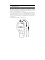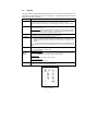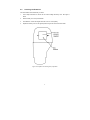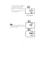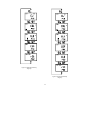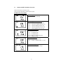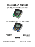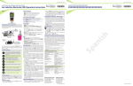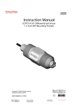
1
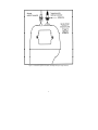
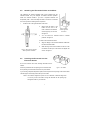
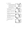
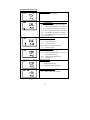
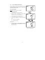
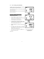
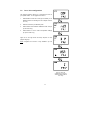
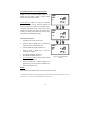
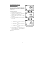
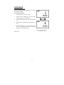
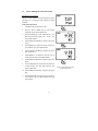
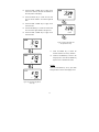
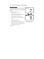
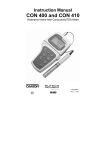
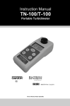
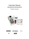
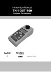
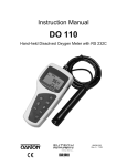
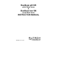
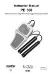
Instruction Manual pH 300/310 Waterproof Hand-held pH / mV / Temperature Meter 68X248901 Technology Made Easy ... Part of Thermo Fisher Scientific Rev 9 Jun 07 Preface This manual serves to explain the use of the waterproof pH 300/310 hand-held meter. It functions in two ways, firstly as a step by step guide to help you to operate the meter. Secondly, it serves as a handy reference guide. It is written to cover as many anticipated applications of the waterproof pH 300/310 meter as possible. If there are doubts in the use of the meter, please do not hesitate to contact the nearest Authorized Distributor. Eutech Instruments/ Oakton Instruments cannot accept any responsibility for damage or malfunction to the meter caused by improper use of the instrument. The information presented in this manual is subject to change without notice as improvements are made, and does not represent a commitment on the part of Eutech Instruments Pte Ltd/ Oakton Instruments. Copyright © 1999 Eutech Instruments Pte Ltd/ Oakton Instruments All rights reserved. TABLE OF CONTENTS 1 INTRODUCTION 1 2 DISPLAY AND KEYPAD FUNCTIONS 2.1 2.2 2.3 2.4 2.5 2.6 Display Keypad Inserting the Batteries Connecting the Electrode and Temperature Probe Attaching the Electrode Holder to the Meter Inserting the Electrode into the Electrode Holder 3 CALIBRATION 3.1 3.2 3.3 3.4 3.5 Important Information on Meter Calibration Preparing the Meter for Calibration pH Calibration Relative mV Calibration Temperature Calibration 4 MEASUREMENT 4.1 4.2 4.3 Automatic Temperature Compensation Manual Temperature Compensation Taking Measurements 5 HOLD FUNCTION 6 MEMORY FUNCTION 6.1 6.2 Memory Input Memory Recall 7 ADVANCED SETUP FUNCTIONS 7.1 7.2 7.3 7.4 7.5 7.6 7.7 7.8 Advanced SET-UP Mode Overview P 1.0: Memory Clear (CLr) P2.0: Viewing previous calibration data P3.0: Viewing electrode data P4.0: Unit configuration P5.0: Resetting to factory default settings P5.0: Setting the real-time clock P6.0: Resetting to factory default settings 8 PROBE CARE AND MAINTENANCE 38 9 TROUBLE SHOOTING GUIDE 40 10 ERROR MESSAGES 41 11 SPECIFICATIONS 42 12 ACCESSORIES 43 13 ADDENDUM 1: METER FACTORY DEFAULT SETTINGS 46 14 WARRANTY 47 15 RETURN OF ITEMS 48 2 2 3 4 5 7 7 8 8 8 10 12 13 14 14 15 16 17 18 18 19 21 23 25 26 27 29 34 35 37 1 INTRODUCTION Thank you for selecting this meter. The waterproof pH 300/310 Hand-held meter is a microprocessor-based instrument that is designed to be handy and user-friendly. It is capable of measuring pH, mV and temperature. It is designed to be handy and capable of allowing one-hand operation. It is completely WATERPROOF --- and it FLOATS! This meter has many user-friendly features – all of which are completely accessible through the water-resistant membrane keypad. Your meter includes a temperature probe, two electrode holders, batteries, instruction manual and a warranty card. Complete portable testing versions, including a rugged carrying case and calibration solutions, are also available. Refer to the Accessories section for more information. Please read this manual thoroughly before operating your meter. 1 2 2.1 DISPLAY AND KEYPAD FUNCTIONS Display The LCD has a primary and secondary display. • The primary display shows the measured pH, mV or Relative mV value. • The secondary display shows the measured temperature. The display also shows error messages, keypad functions and program functions. See Figure 1. Figure 1: Full LCD Screen 1. SETup mode indicator 7. Temperature indicator (°F available on pH 310 meter only) 13. Low battery indicator 2. MEASurement mode indicator 8. pH buffer selection indicator 14. Probe indicator 3. CALibration indicator 9. Automatic Temperature Compensation indicator 15. Buffer indicator 4. MEMory recall mode indicator 10. Clock indicator (pH 310 meter only) 16. Function ON/OFF indicator 5. mV or Relative mV indicator 11. ERRor indicator 17. HOLD indicator 6. pH indicator 12. MEMory location indicator 18. READY indicator 2 2.2 Keypad The large membrane keypad makes the instrument easy to use. Each button, when pressed, has a corresponding graphic indicator on the LCD. See Figure 2. Some buttons have several functions depending on its mode of operation. Key Function ON/OFF Powers on and shuts off the meter. When you switch on the meter, the meter starts up in the mode that you last switched off from. For example, if you shut the meter off in mV measurement mode, the meter will be in mV measurement mode when you switch the meter on. HOLD Freezes the measured reading. To activate, press HOLD while in measurement mode. To release, press HOLD again. pH 310 model only: When auto endpoint feature is switched on, it automatically holds reading after 5 seconds of stability. The HOLD indicator appears on the display. Press HOLD to release auto endpoint feature. MODE Selects the measurement parameter. Press MODE to toggle between pH, mV (or relative mV) and date/time [date/time feature available on pH 310 model only]. CAL/MEAS Toggles between Calibration and Measurement mode. 1. If you were in pH Measurement mode, press CAL/MEAS to enter pH Calibration mode. NOTE: Temperature calibration is available from pH Calibration mode. See page 13 for directions. 2. If you were in mV Measurement mode, press CAL/MEAS to enter mV Calibration mode. While in SETUP main menu, pressing CAL/MEAS takes you out directly into the measurement mode. ENTER 1. To confirm your calibration values in Calibration mode. 2. To confirm selections in SETUP mode. In Measurement mode: MI/▲ & MR/▼ Press MI/▲ (memory input) to store values with its corresponding temperature values in the memory. Press MR/▼ (memory recall) to retrieve data from memory. In SETUP mode: Press to scroll through the setup subgroup programs. In mV calibration mode: Press to adjust the calibration value. SETUP Takes you into the SETUP mode. This mode lets you customize meter preference and defaults, and view calibration and electrode offset data. Figure 2 - Keypad 3 2.3 Inserting the Batteries Four AAA batteries are included with your meter. 1. Use a Philips screwdriver to remove the two screws holding the battery cover. See Figure 3 below. 2. Remove battery cover to expose batteries. 3. Insert batteries. Follow the diagram inside the cover for correct polarity. 4. Replace the battery cover into its original position using the two screws removed earlier. Figure 3 - Back panel of meter showing battery compartment 4 2.4 Connecting the Electrode and Temperature Probe The waterproof pH 300/310 handheld pH meter uses any standard pH, ORP, or ISE electrode with a BNC connector. For Automatic Temperature Compensation (ATC), this meter requires a temperature probe with a special 6-pin connector. Use either: • All electrode with a BNC connector and a separate temperature probe with 6-pin connector (EC-PHWPTEM-01W/ 35618-05). • A “3-in-1” combination pH electrode with temperature probe designed specifically for pH 300 and pH 310 waterproof meters. Refer to “Accessories” section on page 43 for more information on temperature probe and other electrodes. NOTE: Keep connectors dry and clean. Do not touch connector with soiled hands. To connect the pH, ORP or ISE electrode: 1. Slide the BNC connector of the probe over the BNC connector socket on the meter. Make sure the slots of the connector are in line with the posts of the socket. Rotate and push the connector clockwise until it locks. 5. To remove electrode, push and rotate the connector counterclockwise. While holding onto the metal part of the connector, pull it away from the meter. CAUTION: Do not pull on the probe cord or the probe wires might disconnect. To connect the temperature probe: 1. Line up the notch and 6 pins on the probe connector with the holes in the connector located on the top of the meter. Push down and screw the metal sleeve to lock the probe connector into place. See Figure 4. 6. To remove probe, unscrew the metal sleeve and slide up the probe connector. While holding onto metal sleeve, pull probe away from the meter. CAUTION: Do not pull on the probe cord or the probe wires might disconnect. 5 Figure 4 - Connection for pH Electrode (BNC) and Temperature probe (6-pin connector) 6 2.5 Attaching the Electrode Holder to the Meter The waterproof pH 300/310 handheld meter comes complete with two electrode holders. They are designed to facilitate one-hand operation. Attach two electrode holders if you have a separate electrode and temperature probe. Care must always be taken to avoid use of excessive force in the process of attaching these components. 1. Locate the slot on the right-hand side of the meter. 2. Gently slide the flange of the holder into the slot on the meter. Make sure the holder is secured properly into the slot. Figure 5 - Holder slot into right-hand side of meter See figure 5. 3. You can attach the electrode holder in different positions. See figure 6. To attach a second electrode holder: 4. Align the flange of the second electrode holder with the slot of the first holder. 5. Slide the flange of the second holder into the slot of the first holder until the tops of the holders are aligned and Figure 6 - Electrode can be placed in different positions with holder 2.6 secure. See figure 7. Inserting the Electrode into the Electrode Holder Do not use excessive force when inserting electrodes into the holders. Insert the pH electrode into the opening of the first holder until Figure 7 - Two holders the top housing of the electrode touches the top of the holder. If you are using a separate temperature probe, insert the probe into the opening of the second holder until the ridge on the housing touches the top of the holder. NOTE: The holder is designed for probes 12 mm in diameter. Electrodes larger than 12 mm may not fit in the holder. Forcing the electrode into the opening may damage the holder or your electrode. 7 3 3.1 CALIBRATION Important Information on Meter Calibration When you re-calibrate your meter, old pH, Rel mV and mV calibration points are replaced on a point by point basis. For example, if you previously calibrated your meter at pH 4.01, 7.00, and 10.01, and you have now re-calibrated at pH 7.00, the meter retains the old calibration data at pH 4.01 and pH 10.01. To view current calibration points, see Program P2.0 in the SETUP section on page 26. To completely re-calibrate your meter, or when you use a replacement probe, it is best to set the meter to its factory defaults and re-calibrate the meter at all points. To reset the meter to its factory defaults, see the SETUP section, Program P5.0, page 34 (for pH 300 meter) or Program P6.0, page 37 (for pH 310 meter). 3.2 Preparing the Meter for Calibration Before starting calibration, make sure you are in the correct measurement mode. When you switch on the meter, the meter starts up in the units last used. For example, if you shut the meter off in “mV” units, the meter will read “mV” units when you switch the meter on. Be sure to remove the protective electrode storage bottle or rubber cap of the electrode before calibration or measurement. If the electrode has been stored dry, wet the electrode in tap water for 10 minutes before calibrating or taking readings to saturate the pH electrode surface and minimize drift. Wash your electrode in deionized water after use, and store in electrode storage solution. If storage solution is not available, use pH 4.01 or 7.00 buffer solution. Do not reuse buffer solutions after calibration. Contaminants in the solution can affect the calibration, and eventually the accuracy of the measurements. See page 43 for information on our high-quality pH buffer solutions. 8 pH 300 meter calibration The pH 300 meter is capable of up to 5-point pH calibration to ensure accuracy across the entire pH range of the meter. Select from the following buffer options: • USA buffers --- pH 1.68; 4.01, 7.00, 10.01, and 12.45. The meter automatically recognizes and calibrates to these standard buffer values, which makes pH calibration faster and easier. pH 310 meter calibration The pH 310 meter features three separate internationally-recognized buffer standards. Select the buffer standard you require in SETUP mode Program 4.0 (see pages 27 & 34 for more information). The pH 310 meter is capable of up to 6-point pH calibration, depending on the buffer standard selection. Select from the following buffer options: • USA buffers --- pH 1.68, 4.01, 7.00, 10.01, and 12.45. • NIST buffers --- pH 1.68, 4.01, 6.86, 9.18, and 12.45. • DIN buffers --- pH 1.09, 3.06, 4.65, 6.79, 9.23, and 12.75. The meter automatically recognizes and calibrates to these standard buffer values, which makes pH calibration faster and easier. 9 3.3 pH Calibration NOTE: We recommend that you perform at least 2-point calibration using standard buffers that bracket (one above and one below) the expected sample range. You can perform a 1-point calibration, but make sure that the buffer value is close to the sample value you are measuring. 4. If necessary, press the MODE key to select pH mode. The pH indicator appears in the upper right hand corner of the display. 5. Rinse the probe thoroughly with de-ionized water or a rinse solution. Do not wipe the probe; this causes a build-up of electrostatic charge on the glass surface. 6. Dip the probe into the calibration buffer. The end of the probe must be completely immersed into the sample. Stir the probe gently to create a homogeneous sample. 7. Press CAL/MEAS to enter pH calibration mode. The CAL indicator will be shown. The primary display will show the measured reading while the smaller secondary display will indicate the pH standard buffer solution. 8. Wait for the measured pH value to stabilize. 9. Press ENTER to confirm calibration. The meter is now calibrated to the current buffer. See figure 8. Figure 8 - pH Calibration 10 7. Rinse the probe with de-ionized water or a rinse solution, and place it in the next pH buffer. 8. Follow steps 5 and 6 for additional calibration points. See Figure 9. 9. When all the calibration points as set in the Unit Configuration Setup (see P4.2 on page 31) are completed, the meter returns to Measurement mode automatically. However, if you wish to terminate the calibration without completing the number of points as set in the Unit Configuration Setup menu, press CAL/MEAS to return to pH measurement mode. NOTES: Figure 9 - Next point calibration for pH 4.01 To exit from pH calibration mode without confirming calibration, DO NOT press ENTER in step 6. Press CAL/MEAS instead. If the selected buffer value is not within ±1.0 pH from the measured pH value: the electrode and buffer icon blink and the ERR annunciator appears in the lower left corner of the display. Figure 10. To limit the number of pH buffer values available during calibration, see SETUP section P4.2 on page 31. Figure 10 - Err message and electrode icon will appear if incorrect buffer are used 11 3.4 10. Relative mV Calibration While in the measurement function, press MODE to enter the mV mode. The mV indicator appears in the upper right hand corner. See figure at right. 11. Press the CAL/MEAS key. The CAL indicator appears above the primary display. The primary display shows the relative mV reading and the secondary display shows the absolute mV value. NOTE: If you have never calibrated relative mV or if the meter has been reset, the value shown in the primary display is the same as the absolute mV value. NOTE: “R.” annunciator will appear once mV calibration is performed, an indication of mV offset. 12. Press the MI/▲ or MR/▼keys to enter the relative mV value that matches your desired reading. 13. Press the ENTER key to confirm the reading and to return to the measurement mode. The primary display now shows the relative mV reading. NOTES: To view the mV offset value, use the SETUP mode Program P3.1. See page 27 for instructions. To reset all calibration and offset values in memory to the factory default settings, use: • In pH 300 meter: SETUP Program P 5.0. See page 34. • In pH 310 meter: SETUP Program P 6.0. See page 37. Figure 11 - mV calibration 12 3.5 Temperature Calibration The temperature sensor is factory calibrated. Calibrate the temperature probe only if you suspect temperature errors that may have occurred over a long period of time or if you have a replacement probe. Temperature Calibration 14. Make sure the ATC probe (or temperature connector of the electrode) is attached to the 6-pin connector. The ATC annunciator will appear at the right-hand side of the LCD. 15. Switch the meter on. Press the MODE key to select pH mode. 16. Press the CAL/MEAS key to enter pH calibration mode. The CAL indicator will appear above the primary display. 17. While in pH calibration mode, press the MODE key to enter temperature calibration mode. The primary display shows the temperature reading with last set offset and the secondary display shows the factory default temperature value. 18. Dip the ATC probe (or electrode) into a solution of known temperature (i.e. a temperature bath). Allow time for the temperature probe to stabilize. 19. Scroll with the MI/▲ or MR/▼ keys to set the correct temperature value (i.e. the temperature of the temperature bath). You can adjust the reading in increments of 0.1 °C. 20. Once you have selected the correct temperature, press the ENTER key. The meter automatically returns to pH measurement mode. See Figure 12. NOTES: • You can offset the temperature reading up to ±5°C from original reading. • To exit this program without confirming the temperature calibration value, DO NOT press ENTER. CAL/MEAS instead. 13 Press Figure 12 - Temperature calibration 4 MEASUREMENT This meter is capable of taking measurements with automatic or manual temperature compensation. Automatic temperature compensation only occurs when a temperature sensor is plugged into the meter. If there is no temperature sensor plugged into the meter, the default manual temperature setting is automatically 25 °C. You can manually set the temperature to match your working conditions using a separate thermometer. 4.1 Automatic Temperature Compensation For automatic temperature compensation (ATC) simply plug the temperature probe into the meter (see page 6 for directions). The ATC indicator will light up on the LCD. See figure 13. NOTE: If you are using a temperature probe, the probe must be submersed in the liquid you are measuring. Figure 13 - ATC annunciator will light up when connected to temperature probe 14 4.2 Manual Temperature Compensation IMPORTANT: For manual compensation, you must disconnect the temperature probe (see page 6). 1. Switch the meter on. Press the MODE key to select pH mode. 2. Press the CAL/MEAS key to enter pH calibration mode. The CAL indicator will appear above the primary display. 3. While in pH calibration mode, press the MODE key to enter temperature calibration mode. The primary display shows the current temperature setting and the secondary display shows the default value 25 °C. 4. Check the temperature of your sample using an accurate thermometer. 5. Press the MI/▲ or MR/▼ keys to set the temperature to the measured value from step 4. 6. Press ENTER to confirm the selected temperature and to return to the pH measurement mode. See Figure 14. The meter will now compensate pH readings for the manually set temperature. NOTES: Figure 14 - Manual temperature compensation To exit this program without confirming the manual temperature compensation value, DO NOT press ENTER in step 6. Press CAL/MEAS instead. 15 4.3 Taking Measurements Be sure to remove the electrode soaker bottle or protective rubber cap on the electrode before measurement. To take readings: 1. Rinse the probe with de-ionized or distilled water before use to remove any impurities adhering to the probe body. If the pH electrode has dehydrated, Figure 15 - Measurement mode soak it for 30 minutes in electrode storage solution or 2M – 4M KCl solution (sold separately). 2. Press ON to switch on meter. The MEAS annunciator appears on the top center of the LCD. The ATC indicator appears in the lower right-hand corner to indicator Automatic Temperature Compensation (see page 15 to set Manual Temperature Compensation). See Figure 15. 3. Dip the probe into the sample. When dipping the probe into the sample, the sensor or the glass bulb of the electrode must be completely immersed into the sample. Stir the probe gently in the sample to create a homogeneous sample. 4. Allow time for the reading to stabilize. Note the reading on the display. 5. To toggle between pH and mV (or Rel mV) readings, press the MODE key. Taking measurements with READY indicator selected on If the READY indicator has been activated, the READY annunciator lights when the reading is stable *. Switch the READY indicator on or off in SETUP program P 4.1. See page 30 for directions. * The READY indicator appears and the reading holds until the measured value exceeds the tolerance (±0.02 pH; ± 0.8 mV <400; ±1.2 mV > 400). Then, the READY annunciator turns off. Taking measurements with the auto endpoint feature selected on NOTE: This feature is available on model pH 310 only. When a reading is stable for more than 5 seconds, the auto endpoint feature will automatically “hold” the reading. The “hold” indicator appears on the left side of the display. Press the HOLD key to release the reading. Switch the Auto endpoint feature on or off in SETUP program P 4.1, see page 30 for instructions. 16 5 HOLD FUNCTION This feature lets you freeze the value of the pH, mV (or Relative mV) and temperature readings for a delayed observation. HOLD can be used any time when in MEAS mode. 1. To hold a measurement, press the HOLD key while in measurement mode. “HOLD” will appear on the display. See Figure 16. 2. To release the held value, press HOLD again. Continue to take measurements. NOTE: Figure 16 - HOLD feature This meter shuts off automatically 30 minutes after last key is pressed. If the meter is shut off either automatically or manually, the HOLD value will be lost. For longer storage, use the Memory functions described in page 18. NOTE: for pH 310 model only: The pH 310 meter has an auto endpoint feature. When this feature is switched on, the display will automatically “HOLD” a reading that has been stable for more than 5 seconds. The “HOLD” indicator appears. Press the HOLD key to release the reading. To switch on or off the auto endpoint feature, see SETUP Program P 4.1 on page 30. 17 6 MEMORY FUNCTION 6.1 Memory Input Your meter stores data in sets: • pH and temperature • mV (or relative mV) and temperature For pH 300 meter: The pH 300 meter can store up to 16 sets of data in any combination of values. For example, you can store 7 pH and 9 mV values. For pH 310 meter: The pH 310 meter can store up to 50 sets of data in any combination of values. In addition to the standard data set, the pH 310 meter also stores the date and time the reading was stored. To store a reading: 1. During any measurement function (MEAS), press MI key to input any data into the memory. 2. MEM, “Sto” and memory number will flash. The meter then returns to measurement mode. See figure 17. NOTE: If the memory is full, the first value stored will be erased to create space for the new value. Figure 17 - Memory Input 18 6.2 Memory Recall This function recalls the previous readings stored in the memory. You can only access MR from the measurement mode. Memory recall is in “Last In First Out” order. To recall readings: 1. Press the MR key once to retrieve the last reading stored. The memory location screen – MEM, “Loc” and the memory number – will flash on the display. 2. Press the ENTER key to recall the reading stored under that memory number. For pH 300 meter only: Press the ENTER key again to return to the “memory location” screen. See Figure 18. For pH 310 meter only: Press the ENTER key again to view the date (Month/Day format) and time (Hour/Minute format) the reading was taken. See Figure 19. Press ENTER key again to return to the “memory location” screen. 3. The display automatically moves to the next lower Figure 18 - Memory recall function memory location screen. See figure 20. 19 4. If necessary, press the MI/▲ key to select the next “memory location” screen; press the MR/▼ key to select the previous “memory location” screen. 5. Repeat steps 2 to 5 to review additional stored data sets. 6. To exit Memory Recall, press the MEAS key to return to the Measurement mode. Figure 19 - View date and time (available only for pH 310 meter) NOTES: Readings stored in memory are retained even if the units are turned off. To erase all readings stored in memory, use the SETUP mode P1.0 on page 25. Figure 20 - Next Memory Recall value 20 7 ADVANCED SETUP FUNCTIONS The advanced setup mode lets you customized your meter’s preferences and defaults. This meter features different sub groups that organize all setup parameters. The sub-groups are: 1. P1.0: Memory clear (CLr) 2. P2.0: Viewing calibration data (CAL) 3. P3.0: Viewing electrode data (ELE) 4. P4.0: Unit configuration (COF) 5. 6. P5.0 (pH 300 only): Reset to factory default settings (rSt) P5.0 (pH 310 only): Setting clock (CLO) P6.0 (pH 310 only): Reset to factory default settings (rSt) See Figure 21 and 22. 21 Figure 21 - pH 300 Advanced Setup Subgroups Figure 22 - pH 310 Advanced Setup Subgroups 22 7.1 Advanced SET-UP Mode Overview Press the SETUP key to enter Set up mode. Press the MI/▲ or MR/▼ keys to scroll through sub groups. pH 300 meter set up mode P1.0: Memory clear P1.0 Clear all stored readings P2.0: Viewing previous calibration data P2.1 View first calibration point (pH 1.68) P2.2 View second calibration point (pH 4.01) P2.3 View third calibration point (pH 7.00) P2.4 View fourth calibration point (pH 10.01) P2.5 View fifth calibration point (pH 12.45) P3.0: Viewing electrode data In pH measurement mode: P3.1 pH electrode offset P3.2 pH electrode slope In mV (or relative mV) measurement mode: P3.1 Relative mV offset P4.0: Unit configuration P4.1 READY indicator on or off P4.2 Number of calibration points: 2, 3, 4 or 5 P5.0: Reset to factory default P5.0 Reset to factory default settings 23 pH 310 meter setup mode P1.0: Memory clear P1.0 Clear all stored readings P2.0: Viewing previous calibration data (USA, NIST or DIN standards) P2.1 First calibration point (plus time and date) P2.2 Second calibration point (plus time and date) P2.3 Third calibration point (plus time and date) P2.4 Fourth calibration point (plus time and date) P2.5 Fifth calibration point (plus time and date) P2.6 Sixth calibration point (plus time and date) (only for DIN buffer set) P3.0: Viewing electrode data In pH measurement mode: P3.1 pH electrode offset P3.2 pH electrode slope In mV (or relative mV) measurement mode: P3.1 Relative mV offset P4.0: Unit configuration P4.1 READY indicator on or off P4.2 Number of calibration points: 2, 3, 4 or 5 (or 6 for DIN buffer set only) P4.3 Calibration buffer selection sets P4.4 Selecting °C or °F P5.0: Setting Clock • Setting year • Setting date (month/day) • Setting time (hour/minute/second) P6.0: Reset to factory default P6.0 Reset to factory default settings 24 7.2 P 1.0: Memory Clear (CLr) Use this parameter to clear all memory values when you need to store a new series of values. This lets you avoid confusing the old values with the new ones. NO is the default setting. NOTE: Selecting YES will wipe out all memory. From measurement mode: 1. Press the SETUP key to enter Set Up mode. 2. Press the MI/▲ or MR/▼ keys to scroll through subgroups until you view the parameter P1.0. 3. Press the ENTER key to enter parameter P1.0. 4. Press the MI/▲ or MR/▼ keys to toggle between NO and YES. z NO retains current memory z YES clears all memory. See Figure 23. 5. Press the ENTER key to confirm selection and return to the subgroup menu. Press CAL/MEAS key to return to measurement mode. Figure 23 - P1.0: Memory Clear 25 7.3 P2.0: Viewing previous calibration data This mode lets you recall previous calibration data, which helps you know when to re-calibrate your meter. This is a “view only” mode. From measurement mode: 1. Press the SETUP key to enter Set up mode. 2. Press the MI/▲ or MR/▼ keys to scroll through subgroups until you view parameter P2.0. 3. pH 300 meter only: Press the ENTER key repeatedly to view previous calibration data. See Figure 24. pH 310 meter only: Press the ENTER key repeatedly to view previous calibration data. The meter will first display the calibration point, and then display the date and time of calibration. See Figure 25. 4. When you have scrolled through all calibration data, you will automatically return to the subgroup menu. Press CAL/MEAS key to return to measurement mode. Figure 24 - P2.0: View calibration data Figure 25 - Time/date appears on pH 310 meter display only NOTES: If there is no previous calibration data at a particular point, the primary display will show “ ----“. 26 7.4 P3.0: Viewing electrode data Program 3 has two “view only” options that let you check the electrode parameters for diagnostic purposes. From pH measurement mode, you can view the electrode’s offset and slope values. From mV measurement mode, you can view the electrode’s relative mV offset value. P3.1 & P3.2 : Electrode offset and slope From pH measurement mode 1. Press the SETUP key to enter Set Up mode. 2. Press the MI/▲ or MR/▼ keys to scroll through subgroups until you view parameter P3.0. 3. Press the ENTER key to select parameter 3.1. 4. The display shows the electrode offset value. It is the mV offset at pH 7.00. If you have not calibrated at any buffer, the primary display shows 0.0 mV. 5. Press the ENTER key to proceed to electrode slope display. 6. The display shows electrode slope in percentage. Slope displayed is the average slope based on the pH calibrations. Default setting is 100.0. 7. At any point, you can press the CAL/MEAS key to return to measurement mode. See figure 26. 27 Figure 26 - Viewing electrode's offset and slope status from pH measurement mode From mV measurement mode If you are in mV measurement mode, the display shows the relative mV offset. You can adjust the relative mV offset in relative mV calibration mode. See page 12 for instructions. 1. If necessary, press the MODE key to select mV measurement mode. 2. From mV measurement mode, press the SETUP key to enter Set Up mode. 3. Press the MI/▲ or MR/▼ keys to scroll through subgroups until you view parameter P3.0. 4. Press the ENTER key to select parameter 3.1. 5. The display shows the electrode offset value. It is the relative mV offset. If you have not calibrated at any mV standards, the primary display shows 0.00 mV. Figure 27 - View electrode offset value from mV measurement mode 6. Press the ENTER key to return to P3.0. 7. At any point, you can press the CAL/MEAS key to return to measurement mode. See figure 27. 28 7.5 P4.0: Unit configuration This subgroup program allows you to customize the meter to your specific needs. You can program the meter to: 1. Select READY function ON or OFF (pH 310 allows you an additional feature of switching the Auto endpoint function on or off) 2. Select the number of pH calibration points 3. Select between three standard calibration buffer sets (for pH 310 meter only) 4. Select between °C and °F units for temperature readings (for pH 310 meter only) Figure 28 on the right shows the setup sequence for this program subgroup. NOTE: Programs P4.3 and P4.4 is only available in pH 310 meter. Figure 28 - P4.0: Unit configuration program (P4.3 and P4.4 available on pH 310 meter only) 29 P4.1: READY Indicator and auto endpoint function Program P4.1 lets you select “READY indicator on” to indicate when the reading is stable*, or select “READY indicator off” for faster meter response. pH 310 meter only: Program P4.1 also lets you switch the Auto endpoint function on or off. Select auto endpoint on to “hold” the reading when it is stable for more than 5 seconds. The display automatically freezes, and the HOLD indicator appears on the left side of the display. Press the HOLD key to release the display and access other functions. Select auto endpoint off to deactivate this feature. From measurement mode 1. Press SETUP key to enter Set Up mode. 2. Press the MI/▲ or MR/▼ keys to scroll through subgroups until you view parameter P4.0. 3. Press the ENTER key to select parameter 4.1. 4. Press the MI/▲ or MR/▼ keys to select the configuration you require. • OFF switches the READY indicatory off. • ON switches the READY indicator on. • pH 310 meter only: ON and HOLD together switches Figure 29 - P4.1: Selecting READY function) the auto endpoint feature on. 5. Press the ENTER key to confirm selection and to proceed to step 4 of P4.2. Press the CAL/MEAS key to return to measurement mode. NOTES: Meter default is set for READY indicator on and auto endpoint function off. *The READY indicator appears and the reading holds until the measured value exceeds the tolerance (± 0.02 pH; ± 0.8 mV <400 mV; ± 1.2 mV > 400). Then the READY annunciator turns off. 30 P4.2: Selecting number of pH calibration points Program P4.2 lets you select the number of calibration points that appear in pH calibration mode: 2, 3, 4, or 5. This lets the meter scroll through the calibration points more quickly if you regularly calibrate at less than 5 points. From measurement mode. 1. 2. Press SETUP key to enter Set Up mode. Press the MI/▲ or MR/▼ keys to scroll through subgroups until you view parameter P4.0. 3. Press the ENTER key twice to select parameter 4.2. 4. Press the MI/▲ or MR/▼ keys to select 2, 3, 4, or 5 point pH calibration (up to 6 points for DIN calibration set with pH 310 meter). 5. Press the ENTER key to confirm selection and to return to the subgroup menu. Press CAL/MEAS key to return to measurement mode. See Figure 30. Figure 30 - P4.2: Select number of pH calibration points 31 P4.3 Calibration buffer selection sets Available in pH 310 meter only The pH 310 meter lets you select between three standard calibration buffer sets, depending on your requirements. The available sets are USA, NIST, and DIN standard calibration buffers. From measurement mode 1. Press SETUP key to enter Set Up mode. 2. Press the MI/▲ or MR/▼ keys to scroll through subgroups until you view parameter P4.0. 3. Press the ENTER key three times to select parameter 4.3. 4. Press the MI/▲ or MR/▼ keys to select the buffer set you require: • USA buffers – pH 1.68, 4.01, 7.00, 10.01, and 12.45. • NIST buffers – pH 1.68, 4.01, 6.86, 9.18, and 12.45. • DIN buffers – pH 1.09, 3.06, 4.65, 6.79, 9.23 and 12.75. 5. Figure 31 - P4.3: Select calibration buffer sets (pH 310 meter only) Press the ENTER key to confirm selection and to return to the subgroup menu. Press CAL/MEAS key to return to measurement mode. See Figure 31. 32 P4.4 Selecting °C or °F Available in pH 310 meter only The pH 310 meter lets you select between °C and °F units for temperature readings. From measurement mode 1. 2. Press SETUP key to enter Set Up mode. Press the MI/▲ or MR/▼ keys to scroll through subgroups until you view parameter P4.0. 3. Press the ENTER key four times to select parameter 4.4. 4. Press the MI/▲ or MR/▼ keys to toggle between °C and °F. 5. Press the ENTER key to confirm selection and to return to the subgroup menu. Press the CAL/MEAS key to return to measurement mode. Figure 32 - P4.4: Select temperature units (pH 310 meter only) See Figure 32. 33 7.6 P5.0: Resetting to factory default settings Available in pH 300 meter only In the pH 300 meter, Program 5 lets you reset all parameters to factory default settings. This clears all calibration data, memory, and any other setup functions you might have changed. From measurement mode 1. 2. Press SETUP key to enter Set Up mode. Press the MI/▲ or MR/▼ keys to scroll through subgroups until you view parameter P5.0. 3. Press the ENTER key to enter parameter P5.0. See Figure 33. 4. Press the MI/▲ or MR/▼ keys to toggle between NO and YES. 5. • NO retains current settings • YES resets to factory default settings. Figure 33 - P5.0: Reset to factory default values (pH 300 meter only) Press the ENTER key to confirm selection and to return to the measurement mode. Otherwise press CAL/MEAS key to return to measurement mode without resetting to factory default. 34 7.7 P5.0: Setting the real-time clock Available in pH 310 meter only The pH 310 meter features a real-time calendar and clock. This helps you to meet GLP (Good Laboratory Practice) standards. From measurement mode 1. Press SETUP key to enter Set Up mode. 2. Press the MI/▲ or MR/▼ keys to scroll through subgroups until you view parameter P5.0. 3. Press the ENTER key to enter parameter P5.0. The meter lets you select the century: “19—“ or “20—“. The century digits will flash. 4. Press the MI/▲ or MR/▼ keys to toggle to the correct century. 5. Press ENTER key to confirm the century and move to “year” selection. The “year” digits will flash. 6. Press the MI/▲ or MR/▼keys to toggle to the correct year. See Figure 34. 7. Press ENTER key to confirm the year and move to “month” selection. The “month” digits will flash. 8. Press the MI/▲ or MR/▼ keys to toggle to the correct month. 9. Press the ENTER key to confirm the month and move to “date” selection. The “date” digits will flash. See Figure 34 - P5.0: Setting century and year (pH 310 meter only) Figure 35 (next page). 10. Press the MI/▲ or MR/▼ keys to toggle to the correct date. 11. Press the ENTER key to confirm the date and move to “hour” selection. The “hour” digits will flash. See Figure 36 (next page). 35 12. Press the MI/▲ or MR/▼ keys to toggle to the correct hour. Note the “AM” and “PM” indicator on the lower portion of the display. 13. Press the ENTER key to confirm the hour and move to “minute” selection. The “minute” digits will flash. 14. Press the MI/▲ or MR/▼ keys to toggle to the correct minutes. 15. Press the ENTER key to confirm the minutes and move to “second” digits will flash. See Figure 35. 16. Press the MI/▲ or MR/▼ keys to toggle to the correct seconds. Figure 35 - P5.0: Setting month and date (pH 310 meter only) 17. Press the ENTER key to confirm the seconds and return to “century” selection. 18. Press the CAL/MEAS key to return to the subgroup menu. Press the CAL/MEAS key again to return to measurement mode. NOTES Press the CAL/MEAS key at any point while setting the time to return to the subgroup menu. Figure 36 - P5.0: Select time (pH 310 meter only) 36 7.8 P6.0: Resetting to factory default settings Available in pH 310 meter only In the pH 310 meter, Program 6 lets you reset all parameters to factory default settings. This clears all calibration data, memory, and any other setup functions you might have changed. From measurement mode 1. Press SETUP key to enter Set Up mode. 2. Press the MI/▲ or MR/▼ keys to scroll through subgroups until you view parameter P6.0. 3. 4. Press the ENTER key to enter parameter P6.0. Press the MI/▲ or MR/▼ keys to toggle between NO and YES. • ‘NO’ retains current settings • ‘YES’ resets to factory default settings. 5. Press the ENTER key to confirm selection and to return to the measurement mode. Otherwise press CAL/MEAS key to return to measurement mode without resetting to factory default. See Figure 37. 37 Figure 37 - P6.0: Reset to factory default values (pH 310 meter only) 8 PROBE CARE AND MAINTENANCE Since your pH electrode is susceptible to dirt and contamination, clean it every one to three months depending on the extent and condition of use. NOTE: For specialty electrode care, consult the instruction manual included with your electrode. pH electrode storage For best results, always keep the pH bulb wet. Use the protective electrode storage bottle or rubber cap filled with electrode storage solution to store your electrode. Also, you can store in a pH 4 buffer with 1/100 part of saturated KCl. Other pH buffers are OK for storage, but NEVER use distilled water for storage. After measuring 1. Rinse the pH electrode and reference junction in de-ionized water. 2. Store the electrode as recommended above in “pH electrode storage,” or as recommended by the manufacturer. 3. Prior to next use, rinse the liquid junction with de-ionized water and tap dry – never wipe electrode. NOTE: If this does not restore electrode to normal response, see “Reactivating the pH electrode” section below. pH electrode cleaning • Salt deposits: Dissolve the deposits by immersing the electrode in tap water for ten to fifteen minutes. Then thoroughly rinse with distilled water. • Oil/Grease film: wash electrode pH bulb gently in some detergent and water. Rinse electrode tip with distilled water or use a general purpose electrode cleaner (see the Accessories section for ordering information). • Clogged reference junction: Heat a diluted KCl solution to 60 to 80 °C. Place the sensing part of the electrode into the heated solution for about 10 minutes. Allow the electrode to cool in some unheated KCl solution. • Protein deposits: Prepare a 1% pepsin solution in 0.1 M of HCl. Set the electrode in the solution for five to ten minutes. Rinse the electrode with distilled water. 38 Reactivating the pH electrode If stored and cleaned properly, your pH electrode should be ready for immediate use. However, a dehydrated bulb may cause sluggish response. To rehydrate the bulb, immerse the electrode in a pH 4 buffer solution for 10 to 30 minutes. If this fails, the electrode requires activation. Never touch or rub glass bulb. Contact builds up an electrostatic charge. pH electrode activation (for glass body electrodes only) WARNING: Only qualified persons proficient with the safe handling of dangerous chemicals should perform the procedure below. Provide proper containers, fume hoods, ventilation, and waste disposal. Safety goggles and protective clothing must be worn while performing this procedure. If possible, replace with another electrode instead of performing this re-activation procedure. 1. Dip or stir the pH electrode in alcohol for 5 minutes. 2. Leave the electrode in tap water for 15 minutes. 3. Dip and stir the electrode in concentrate acid (such as HCL or H2SO4) for five minutes. 4. Repeat Step 2. 5. Dip and stir in strong base (NaOH) for five minutes. 6. Leave for 15 minutes in tap water. 7. Now test with standard calibration buffer solutions to see if the electrode yields acceptable results. You may repeat step 3 through 6 up to three times for better response. If the response does not improve, then your electrode is no longer functioning. Replace with a new electrode – call your distributor for information. 39 9 TROUBLE SHOOTING GUIDE Problem Cause Solution Power on but no display a). Batteries not in place a). Check that batteries are in place and making good contact. b). Batteries not in correct polarity (+ and – position). b). Re-insert batteries with correct polarity. c). Weak batteries c). Replace batteries or attach optional AC adapter. a). Air bubbles in probe. a). Tap probe to remove bubbles. b). Dirty probe. b). Clean the probe and re-calibrate. c). Probe not deep enough in sample. c). Make sure sample entirely covers the probe sensors. d). External noise pickup or induction caused by nearby electric motor. d). Move or switch off interfering motor. e). Broken probe. e). Replace probe. See the Accessories section, page 43. a). Dirty / Oily probe. a). Clean probe. See “Probe Care & Maintenance”, page 38- 39. Unstable readings Slow response 40 10 ERROR MESSAGES LCD Display Indicates Cause Solution Err annunciator Unrecognized input from keypad Wrong input in selected mode. Release key. Select valid operations depending on mode. CAL & Err annunciators on / Buffer and electrode indicators blink. Calibration error. Wrong value input at calibration. Check your input value, clean probe. Dirty probe. See Calibration sections or Probe Maintenance section. Battery indicator blinks Low battery level. Need new batteries or battery connection is bad. Clean battery contacts. Replace batteries with fresh ones, noting polarity. Err 1 (in primary display) Memory write error. Instrument too old (> 10 years). Hardware failure. Turn meter on and off again. If message persists, return unit*. Err. 2 (in primary display) Memory checksum error. Hardware failure. Turn meter on and off again. If message persists, return unit*. Err. 3 (in primary display) A/D converter error. Hardware error. Turn meter on and off again. If message persists, return unit*. Err. 4 (in primary display) Keypad error. One or more keys on the keypad are stuck. Turn meter on and off again. If message persists, return unit*. * See “Warranty” and “Return of Items” on pages 47 and 48. If an error message appears in the primary display (the upper row of larger digits), switching off the meter and switching it on again may eliminate the error message. Refer to diagram on right. If error persists, or the meter shows incorrect values, return the meter. For a complete diagram of the display see page 2. 41 11 SPECIFICATIONS SPECIFICATIONS DESCRIPTIONS pH 300 pH 310 pH Range -2.00 to 16.00 pH Yes Yes 0.01 pH / ± 0.01 pH Yes Yes 80 to 110% Yes Yes -10 to 110 °C Yes Yes (14 to 230 °F) No Yes Resolution / Accuracy Slope Range Temperature Range Resolution / Accuracy Millivolt Range (Extended) Resolution / Accuracy Millivolt Range 0.1 °C / ± 0.5 °C (0.1 °F / 0.5 °F) Yes Yes -199.9 to +199.9 mV Yes Yes 0.1 mV / ± 0.2 mV Yes Yes -1999 to +1999 mV Yes Yes 1 mV / ± 2 mV Yes Yes Temperature Compensation Auto / Manual (from 0 to 100 °C) Yes Yes Number of calibration points 1 to 5 (up to 6 for pH 310 using DIN) Yes Yes Number of calibration buffers USA: 1.68, 4.01, 7.00, 10.01, & 12.45 Yes Yes NIST: 1.68, 4.01, 6.86, 9.18, & 12.45 No Yes DIN: 1.09, 3.06, 4.65, 6.79, 9.23, & 12.75 No Yes 80 to 110% Yes Yes Offset up to +/-150 mV Yes Yes Hold Function Yes Yes Auto-hold No Yes Resolution / Accuracy pH Slope Display Relative mV & Offset Display Memory pH or mV plus temperature 16 50 No Yes 20 minutes after last key operation Yes Yes Selectable Yes Yes Inputs BNC & 6-pin military type Yes Yes Display Custom Dual LCD Yes Yes Power Requirements 4 ‘AAA’ Batteries Yes Yes > 200 hours Yes Yes Meter: 19 x 10 x 6 cm; 320 g Yes Yes Date and Time Stamping Auto Power off Averaging/Stability (READY) Battery Life Dimension / Weight Boxed: 24 x 23 x 7 cm; 700 g 42 12 ACCESSORIES Replacement Meter and Meter accessories Item Eutech Instruments Order Code Oakton Instruments Order Code Waterproof pH 300 Hand-held pH meter in carrying case kit. Complete with temperature probe, pH electrode (1m cable) and pH carrying kit set. ECPHWP300/02K 35617-70 Waterproof pH 310 Hand-held pH meter in carrying case kit. Complete with temperature probe, pH electrode (1m cable) and pH carrying kit set. ECPHWP310/02K 35618-72 Hard plastic carrying case kit for pH 300/310 meter. ECPHWPKIT (with 3 pH buffer solution (pH 4.01, 7.00, & 10.01) in 60-ml bottle, and 1 empty rinse/waste water bottle (480-ml) 35614-79 (Includes five of each pH buffer pouch) Waterproof pH 300 Hand-held pH meter complete with temperature probe only. ECPHWP300/01 35618-02 Waterproof pH 310 Hand-held pH meter complete with temperature probe only. ECPHWP310/01 Temperature probe for waterproof pH 300 & pH 310 meters ECPHWPTEM01W 35618-05 Plastic body double junction pH electrode with 1m cable. ECFC7252201B 35641-51 “3-in-1” pH / Temperature combination electrode with 1-m cable for waterproof pH 300/310 meter. ECFC7352901W 35808-71 "Temperature probe sold separately" 35618-12 "Temperature probe sold separately" 43 Calibration Solutions Item Eutech Instruments Order Code pH 4.01 buffer solution, 480 ml bottle (1 pint) EC-BU-4BT Oakton Instruments Order Code 00654-00 pH 7.00 buffer solution, 480 ml bottle (1 pint) EC-BU-7BT 00654-04 pH 10.01 buffer solution, 480 ml bottle (1 pint) EC-BU-10BT 00654-08 pH 4.01 buffer sachets, 20 ml x 20 pcs. EC-BU-4BS 35653-01 pH 7.00 buffer sachets, 20 ml x 20 pcs. EC-BU-7BS 35653-02 pH 10.01 buffer sachets, 20 ml x 20 pcs. EC-BU-10BS 35653-03 pH De-ionized water rinse sachets, 20 ml x 20 pcs EC-RIN-WT 35653-00 pH sachet assortment pack – 5 each of pH 4.01, pH 7.00, pH 10.01 and de-ionized water sachets per box. EC-AST-PK 35653-04 Protein cleaning solution for pH electrode EC-DPC-BT 00653-06 Storage solution for pH electrode EC-RE-005 00653-04 Note: pH buffer solutions (480-ml bottle, 1 pint) have ±0.01 pH accuracy at 25 °C. Sachets are individually sealed, single use pouches containing 20 ml of fresh, contamination free calibration solution. pH buffer sachets have ±0.01 pH accuracy at 25°C. 44 Carrying Case Kit for pH 300/310 45 13 ADDENDUM 1: METER FACTORY DEFAULT SETTINGS Resetting the meter to factory default settings clears all calibration data and most other setup functions you might have changed. The following settings will remain as you have set them: • Temperature unit of measure (°C or °F) – only for pH 310 meter • The temperature offset calibration value. • Clock function – only for pH 310 meter Type CLr Parameter Memory clear P No. P1.0 Default No Remarks Retains your current settings CAL View pH calibration data P2.1 P2.2 –– –– Calibration data for 1st buffer Calibration data for 2nd buffer P2.3 P2.4 –– –– Calibration data for 3rd buffer Calibration data for 4th buffer (only in pH 310 meter) P2.5 P2.6 –– –– Calibration data for 5th buffer Calibration data for 6th buffer (DIN only) ELE View electrode offset View electrode slope P3.1 P3.2 0.00 mV 100.0 % View relative mV offset P3.3 0 mV COF Ready indicator # pH calibration points P4.1 P4.2 Ready On 3 Calibration buffer selection sets(pH 310 meter only) P4.3 USA °C or °F (pH 310 meter) Setting year, date and time (in pH 310 meter only) P4.4 P5.0 No default No default P5.0 P6.0 No CLO rSt pH factory default For pH 300 meter For pH 310 meter 46 No offset adjustment No slope adjustment No mV adjustment Ready indicator on; auto endpoint off 3 pH calibration points available (1 – 5 pt range) °C or °F remains as selected Year, date and time remain as selected Retains your current settings 14 WARRANTY This meter is supplied with a three -year warranty, six-month warranty for probe, against significant deviations in material and workmanship. If repair or adjustment is necessary and has not been the result of abuse or misuse within the designated period, please return – freight pre-paid – and correction will be made without charge. Eutech Instruments/ Oakton Instruments will determine if the product problem is due to deviations or customer misuse. Out of warranty products will be repaired on a charged basis. Exclusions The warranty on your instrument shall not apply to defects resulting from: Improper or inadequate maintenance by customer Unauthorized modification or misuse Operation outside of the environment specifications of the products 47 15 RETURN OF ITEMS Authorization must be obtained from our Customer Service Department or authorized distributor before returning items for any reason. A “Return Goods Authorization” (RGA) form is available through our authorized distributor. Please include data regarding the reason the items are to be returned. For your protection, items must be carefully packed to prevent damage in shipment and insured against possible damage or loss. Eutech Instruments/ Oakton Instruments will not be responsible for damage resulting from careless or insufficient packing. A restocking charge will be made on all unauthorized returns. NOTE: Eutech Instruments Pte Ltd/ Oakton Instruments reserves the right to make improvements in design, construction, and appearance of products without notice. 48 For more information on Eutech Instruments/ Oakton Instruments’ products, contact your nearest distributor or visit our website listed below: Oakton Instruments P.O Box 5136, Vernon Hills, IL 60061, USA Tel: (1) 888-462-5866 Fax: (1) 847-247-2984 E-mail: [email protected] Web-site: www.4oakton.com Eutech Instruments Pte Ltd. Blk 55, Ayer Rajah Crescent, #04-16/24 Singapore 139949 Tel: (65) 6778 6876 Fax: (65) 6773 0836 E-mail: [email protected] Web-site: www.eutechinst.com Distributed by: