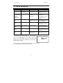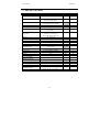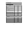
1
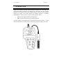
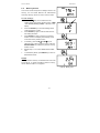
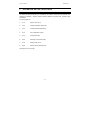
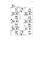
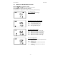
Instruction Manual CON 400 and CON 410 Waterproof Hand-held Conductivity/TDS Meter Technology Made Easy ... 68X248904 Rev 3 01/04 Preface This manual serves to explain the use of the Waterproof CON 400/410 hand-held meters. It functions in two ways, firstly as a step by step guide to help you to operate the meter. Secondly, it serves as a handy reference guide. It is written to cover as many anticipated applications of the Waterproof CON 400/410 meters as possible. If there are doubts in the use of the meter, please do not hesitate to contact the nearest Authorised Distributor. Eutech Instruments/ Oakton Instruments cannot accept any responsibility for damage or malfunction to the meter caused by improper use of the instrument. The information presented in this manual is subject to change without notice as improvements are made, and does not represent a commitment on the part of Eutech Instruments Pte Ltd/ Oakton Instruments. Copyright © 1999 Eutech Instruments Pte Ltd/ Oakton Instruments All rights reserved. Rev 3, 01/04 TABLE OF CONTENTS 1 INTRODUCTION .............................................................................................. 1 2 DISPLAY AND KEYPAD FUNCTIONS............................................................. 2 2.1 2.2 3 PREPARATION ................................................................................................ 4 3.1 3.2 3.3 4 DISPLAY .................................................................................................................... 2 KEYPAD ..................................................................................................................... 3 INSERTING THE BATTERIES ......................................................................................... 4 CONDUCTIVITY ELECTRODE INFORMATION .................................................................. 5 CONNECTING THE PROBE TO THE METER ..................................................................... 6 CALIBRATION.................................................................................................. 7 4.1 IMPORTANT INFORMATION ON METER CALIBRATION ..................................................... 7 4.2 PREPARING THE METER FOR CALIBRATION.................................................................. 8 4.3 TEMPERATURE CALIBRATION ...................................................................................... 9 4.4 CONDUCTIVITY CALIBRATION .................................................................................... 10 4.5 TDS CALIBRATION ................................................................................................... 12 4.5.1 Calibrating for TDS directly ........................................................................... 12 4.5.2 Calibration with Conductivity Standard and TDS factor ................................ 13 5 MEASUREMENT ............................................................................................ 15 5.1 AUTOMATIC TEMPERATURE COMPENSATION ............................................................. 15 5.2 MANUAL TEMPERATURE COMPENSATION .................................................................. 16 5.2.1 Selecting Manual Temperature Compensation............................................. 16 5.2.2 Setting a manual temperature compensation value...................................... 17 5.3 TAKING MEASUREMENTS .......................................................................................... 18 5.4 USING MANUAL RANGING FUNCTION ......................................................................... 19 5.5 HOLD FUNCTION ..................................................................................................... 20 6 MEMORY AND DATA INPUT FUNCTIONS ................................................... 21 6.1 6.2 7 MEMORY INPUT ........................................................................................................ 21 MEMORY RECALL ..................................................................................................... 22 ADVANCED SETUP FUNCTIONS ................................................................. 23 7.1 ADVANCED SETUP MODE OVERVIEW....................................................................... 25 7.2 P 1.0: MEMORY CLEAR (CLR).................................................................................. 27 7.3 P2.0: VIEWING CALIBRATION DATA ............................................................................ 28 7.4 P3.0: VIEWING PROBE DATA ..................................................................................... 29 7.5 P4.0: UNIT CONFIGURATION ..................................................................................... 30 7.5.1 P4.1: READY indicator and auto endpoint function ...................................... 30 7.5.2 P4.2 Selecting °C or °F ................................................................................. 31 7.5.3 P4.3 Selecting Automatic or Manual Temperature Compensation .............. 32 7.5.4 P4.4 Setting the TDS factor ......................................................................... 33 7.6 P5.0 TEMPERATURE ................................................................................................ 34 7.6.1 P5.1 Adjusting the temperature coefficient .................................................. 34 7.6.2 P5.2 Adjusting the normalization temperature ............................................. 35 7.7 P6.0 SELECTING THE CELL CONSTANT ...................................................................... 36 7.8 P7.0: SETTING THE REAL-TIME CLOCK ....................................................................... 37 7.9 P8.0: RESETTING TO FACTORY DEFAULT SETTINGS.................................................... 39 8 PROBE CARE AND MAINTENANCE............................................................. 40 9 TROUBLE SHOOTING GUIDE....................................................................... 41 10 ERROR MESSAGES.................................................................................. 42 11 SPECIFICATIONS ...................................................................................... 43 12 ACCESSORIES .......................................................................................... 44 13 ADDENDUM 1: CALIBRATION TIPS ........................................................ 45 14 ADDENDUM 2: CALCULATING TDS CONVERSION FACTORS .............. 46 14.1 “PREPARING YOUR OWN TDS CALIBRATION STANDARDS”........................................... 46 15 ADDENDUM 3: CALCULATING TEMPERATURE COEFFICIENTS .......... 47 16 ADDENDUM 4: METER FACTORY DEFAULT SETTINGS ....................... 48 17 WARRANTY ............................................................................................... 49 18 RETURN OF ITEMS ................................................................................... 50 Instruction Manual 1 CON 400/410 INTRODUCTION Thank you for selecting the CON 400/410 waterproof portable meter. This meter is a microprocessor-based instrument that is designed to be user-friendly and allow one-hand operation. It has a built-in real time clock, expanded memory, and many other user-friendly features, all of which are accessible through the membrane keypad. It is completely WATERPROOF --- and it FLOATS! You have one of the following models: • CON 400 meter: reads conductivity and temperature. • CON 410 meter: reads conductivity, TDS and temperature. Your meter includes 4 ‘AAA’ batteries and a conductivity electrode (cell constant K = 1.0) with built-in temperature sensor. Please read this manual thoroughly before operating your meter. -1- Instruction Manual 2 CON 400/410 DISPLAY AND KEYPAD FUNCTIONS 2.1 Display The LCD has a primary and secondary display. • The primary display shows the measured conductivity or TDS reading. • The secondary display shows the measured temperature. The display also shows error messages, keypad functions and program functions. See Figure 1. Primary Display 1 SETUP 20 19 READY HOLD ON 18 OFF 3 4 CAL MEM 2 MEAS -8.8.8.8 K= mS µS ppt ppm 5 6 7 8 MEM 17 16 12 15 14 13 ERR °C °F AM PM ATC -1.8.8.8 9 11 Secondary Display 10 Figure 1: Full LCD Screen 1. SETup mode indicator 2. MEASurement mode indicator 3. CALibration indicator 4. MEMory recall mode indicator 5. millisiemens indicator 6. microsiemens indicator 7. parts per thousand indicator (CON 410 meter only) 8. parts per million indicator (CON 410 meter only) 9. Temperature indicator 10. Automatic Temperature Compensation indicator 11. Clock indicator 12. ERRor indicator 13. MEMory location indicator 14. Low battery indicator -2- 15. Probe indicator 16. Calibration solution indicator 17. Cell constant indicator 18. ON / OFF indicator 19. HOLD indicator 20. READY indicator Instruction Manual 2.2 CON 400/410 Keypad The large membrane keypad makes the instrument easy to use. Each button, when pressed, has a corresponding graphic indicator on the LCD. See Figure 2. Some buttons have several functions depending on its mode of operation. Key Function ON/OFF Powers on and shuts off the meter. When you switch on the meter, the meter starts up in the mode that you last switched off from. For example, if you shut the meter off in TDS measurement mode (only in CON 410 meter), the meter will be in TDS measurement mode when you switch the meter on. HOLD Freezes the measured reading. To activate, press HOLD while in measurement mode. To release, press HOLD again. MODE Selects the measurement parameter. ~ CON 400 meter: Toggles between conductivity and time. ~ CON 410 meter: Toggles between conductivity, TDS and time. CAL/MEAS Toggles between Calibration and Measurement mode. NOTE: Temperature calibration is available from conductivity calibration mode; see page 9 for directions. ENTER / RANGE ENTER function: Press to confirm values in Calibration mode and to confirm selections in SETUP mode. RANGE function: Press to enter manual ranging function. The MEAS indicator blinks while in manual ranging function. MI/S and MR/T SETUP In Measurement mode: Press MI/S (memory input) to store values with its corresponding temperature values in the memory. Press MR/T (memory recall) to retrieve data from memory. In Calibration mode: Press to scroll through calibration values. In SETUP mode: Press to scroll through the setup subgroup programmes. Takes you into the SETUP mode. This mode lets you customise meter preference and defaults, and view calibration, electrode offset data and select cell constant. Figure 2 - Keypad -3- Instruction Manual 3 3.1 CON 400/410 PREPARATION Inserting the Batteries Four AAA batteries are included with your meter. 1. Use a Philips screwdriver to remove the two screws holding the battery cover. See Figure 3 below. 2. Remove battery cover to expose batteries. 3. Insert batteries. Follow the diagram inside the cover for correct polarity. 4. Replace the battery cover into its original position using the two screws removed earlier. Figure 3 - Back panel of meter showing meter compartment -4- Instruction Manual 3.2 CON 400/410 Conductivity Electrode Information The CON400/410 meter uses a conductivity / TDS cell with a sturdy 6-pin connector. Your meter includes a conductivity probe (Part No: ECCONSEN91W / 35608-50) Ultem / Stainless Steel cells with a cell constant of K = 1.0. This conductivity / TDS cell features a built-in temperature sensor for Automatic Temperature Compensation (ATC). It has a specially designed housing that provides fast temperature response and reduces air bubble entrapment, which makes it easy to obtain accurate, stable readings. Wetted parts include: 1. Polyetherimide (Ultem™) 2. Polybutylterphalate (Valox™) 3. Stainless Steel (SS 304) 1 NOTE: We recommend that you do not submerge the probe above the protective yellow cap for prolonged periods. The protective yellow cap can be removed for cleaning, but must be attached at all times during calibration or measurment. See Section 8 on page 40 for “Probe Care and Maintenance” information. Figure 4 - Conductivity probe (EC-CONSEN91W/ 35608-50) 1 Valox and Ultem are trademark names of General Electric Co. -5- Instruction Manual 3.3 1. CON 400/410 Connecting the probe to the meter Line up the notch and 6 pins on the meter with the holes in the 6-pin connector. Push down and turn the locking ring clockwise to lock into place. See figure below. 2. To remove probe, turn the locking ring counterclockwise on the probe connector. Pull probe away from the meter. CAUTION: Do not pull on the probe cord or the probe wires might disconnect. NOTE: Keep connectors clean. Do not touch connector with soiled hands. Figure 5 - Connection for Conductivity probe (6-pin connector) -6- Instruction Manual 4 CON 400/410 CALIBRATION 4.1 Important Information on Meter Calibration Your meter has five measuring ranges. You can calibrate one point in each of the measuring ranges (up to five points). If you are measuring values in more than one range, make sure to calibrate each of the ranges you are measuring. To view current calibration points, see SETUP section Program 2.0 on page 28. The following table lists the corresponding conductivity and TDS ranges. You should calibrate each range using a solution that falls between the values in the “recommended calibration solution range” column. Conductivity Measuring Range 0.00 Æ 19.99 µS 0.0 Æ 199.9 µS 0 Æ 1999 µS 0.00 Æ 19.99 mS 0.0 Æ 199.9 mS Recommended Calibration Solution Range 6.00 to 17.00 µS 60.0 to 170.0 µS 600 to 1700 µS 6.00 to 17.00 mS 60.0 to 170.0 mS TDS Measuring Range 0.00 Æ 9.99 ppm 10.0 Æ 99.9 ppm 100 Æ 999 ppm 1.00 Æ 9.99 ppt 10.0 Æ 200 ppt Recommended Calibration Solution Range 3.00 to 8.50 ppm 30.0 to 85.0 ppm 300 to 850 ppm 3.00 to 8.50 ppt 30.0 to 170 ppt When you recalibrate your meter, old calibrations are replaced on a range by range basis. For example, if you previously calibrated your conductivity meter at 1413 µS in the 0 to 1999 µS range and you recalibrate at 1500 µS (also in the 0 to 1999 µS range), the meter will replace the old calibration data (1413 µS) in that range. The meter will retain all calibration data in other ranges. To completely recalibrate your meter, or when you use a replacement probe, it is best to clear all calibration data in memory. To erase all the old conductivity and TDS calibration data completely from memory, see SETUP section Program 8.0 on page 39. For information on how to calibrate your meter: • See section 4.3 for Temperature Calibration. • See section 4.4 for Conductivity • See section 4.5 for TDS Calibration (CON 410 meter only). • See Addendum 1 for more calibration tips. -7- Instruction Manual 4.2 CON 400/410 Preparing the Meter for Calibration Before starting calibration, make sure you are in the correct measurement mode. When you switch on the meter, the meter begins with the units you shut it off in. For best results, select a standard value close to the sample value you are measuring. Alternatively use a calibration solution value that is approximately 2/3 the full-scale value of the measurement range you plan to use. For example, in the 0 to 1999 µS conductivity range, use a 1413 µS solution for calibration. Do not reuse calibration solutions after calibration. Contaminants in the solution can affect the calibration, and eventually the accuracy of the measurements. Use fresh calibration solution each time you calibrate your meter. NOTE: Your meter is factory set to a temperature coefficient of 2.1% per °C. For most applications this will provide good results. See Program P5.1 on page 34 to set the temperature coefficient to different value. See Addendum 3, “Calculating Temperature Coefficients” to determine the appropriate temperature coefficient for your solution. NOTE: The factory default value for normalization temperature is 25 °C. If you need to normalize to a value other than 25 °C, see Program P5.2 on page 35. -8- Instruction Manual 4.3 CON 400/410 Temperature Calibration MEAS 1413 Your probe features a built-in temperature sensor. The temperature sensor is factory calibrated. Calibrate your 22.3 sensor only if you suspect temperature errors that may have occurred over a long period of time or if you have a replacement probe. ATC CAL 1413 µS °C 22.3 ATC DE MO CAL 22.3 22.3 MI °C ATC MR CAL * If the ATC indicator does not light up, see Program P4.3 22.0 to switch it on. 22.3 NOTES: You can offset the temperature reading up to ±5°C from the original reading (default reading). • °C L CA AS E M Temperature Calibration 1. Make sure the cell is attached to the 6-pin connector. The ATC annunciator will appear at the right-hand side of the LCD*. 2. Switch the meter on. Press the MODE key to select conductivity or TDS mode. 3. Press the CAL/MEAS key to enter conductivity or TDS calibration mode. The CAL indicator appears above the primary display. 4. While in conductivity or TDS calibration mode, press the MODE key to enter temperature calibration mode. The primary display shows the current temperature reading and the secondary display shows the factory default temperature value. 5. Dip the cell into a solution of known temperature (i.e. A temperature bath). Allow time for the built-in temperature sensor to stabilise. 6. Scroll with the MI/S or MR/T keys to set the correct temperature value (i.e. the temperature of the temperature bath). You can adjust the reading in increments of 0.1 °C. 7. Once you have selected the correct temperature, press the ENTER key. • µS °C ATC ER ENT GE RAN To exit this program without confirming the temperature calibration value, DO NOT press ENTER. Press MEAS CAL/MEAS instead. • If the ATC indicator does not light, see Program P4.3, on page 32 to switch it on. • Since temperature readings affect the accuracy of the conductivity/TDS recommended measurements, to carry out a it is strongly READY 1425 22.0 µS °C ATC conductivity/TDS calibration after a temperature calibration is done. -9- Figure 10 - Temperature Calibration Instruction Manual 4.4 CON 400/410 Conductivity Calibration The CON 400 and CON 410 meters are capable of up to 5-point conductivity calibration at one point per conductivity range (0.00 - 19.99 µS; 0.0 - 199.9 µS; 0 1999 µS; 0.00 - 19.99 mS; 0.0 - 199.9 mS). All new calibration data will over-ride existing stored calibration data for each measuring range calibrated. Calibrating for Conductivity: 1. If necessary, press the MODE key to select conductivity mode. 2. Rinse the probe thoroughly with de-ionized (DI) water or a rinse solution, then rinse with a small amount of calibration standard. 3. With the yellow probe guard attached, dip the probe into the calibration standard. Immerse the probe tip beyond the upper steel band. Stir the probe gently to create a homogeneous sample. Allow time for the reading to stabilizse. See Figure 7. 4. Press CAL/MEAS to enter conductivity calibration mode. The CAL indicator will appear in the upper right corner of the display. 5. Press the MI/S or MR/T key to change the value on the primary display to match the value of the calibration standard referenced to your normalisation temperature (usually 25°C). 6. Press ENTER to confirm calibration value. The meter returns to the MEAS (measurement) mode. 7. Repeat steps 1 to 6 for other measuring ranges. See figure 6. Figure 6 - Conductivity Calibration - 10 - Instruction Manual CON 400/410 NOTES: When entering calibration mode, the meter displays the factory default value. If the meter was previously calibrated, the display may seem to “jump” to the factory default value when switching from measurement to calibration mode. This is expected. To exit from Conductivity calibration mode without confirming calibration, DO NOT press the ENTER key in step 6. Press CAL/MEAS instead. This will retain the meter’s old calibration data in the measuring range of the calibration. You can offset the conductivity reading up to ±40% from factory default value. If your measured value differs by more than ±40%, clean or replace probe if needed. Figure 7 - Proper Immersion of the conductivity probe The minimum offset reading allowable is limited to 10% of full scale reading of the range you are working in. The maximum offset reading allowed is the range full scale reading Eutech Instruments/ Oakton Instruments offers a wide selection of high-quality calibration standards. See page 44 for more information. - 11 - Instruction Manual 4.5 CON 400/410 TDS Calibration 4.5.1 Calibrating for TDS directly For CON 410 meter only The factory default setting for the TDS conversion factor is 0.50. If your solution has a different TDS factor, you can improve calibration accuracy by setting the TDS factor prior to calibration. See page 33 for directions. 1. If necessary, press the MODE key to select TDS mode. 2. Rinse the probe thoroughly with DI water or a rinse solution, then rinse with a small amount of calibration standard. 3. With the yellow probe guard attached, dip the probe into the calibration standard. Immerse the probe tip beyond the upper steel band. Stir the probe gently to create a homogeneous sample. Allow time for the reading to stabilise. 4. Press CAL/MEAS to enter TDS calibration mode. The CAL indicator will appear in the upper right corner of the display. 5. Press the MI/S or MR/T to change the value on the primary display to match the value of the calibration standard referenced to your normalisation temperature (usually 25°C). 6. Press ENTER to confirm the calibration value. The meter returns to the MEAS (measurement) mode. 7. Repeat steps 1 to 6 for other measuring ranges. NOTES To exit from TDS Calibration mode without confirming calibration, DO NOT press the ENTER key in step 6. Press CAL/MEAS instead. This will retain the meter’s old calibration Figure 8 - TDS Calibration data in the measuring range of the calibration. You can offset the TDS reading up to ±40% from the default setting. If your measured value differs by more than ±40%, clean or replace probe as needed. The minimum offset reading allowable is limited to 10% of full scale reading of the range you are working in. The maximum offset reading allowed is the range full scale reading Eutech Instruments/ Oakton Instruments offer a wide selection of high-quality calibration standards. See page 44 for more information. - 12 - Instruction Manual 4.5.2 CON 400/410 Calibration with Conductivity Standard and TDS factor For CON 410 meter only The concentration of salts dissolved in solution increases the conductivity of that solution. This relationship varies from salt to salt and is roughly linear over a given range for a given salt. The TDS conversion factor is the number used by the meter to convert from conductivity to TDS. Instead of calibrating for TDS directly (described in Section 4.5.1), you can calibrate the CON 410 meter by: 1. calibrating to conductivity standards (as described on pages 10 to 11) and then 2. entering the appropriate TDS conversion factor into the meter. To determine the conductivity to TDS conversion factor for your solution: • Addendum 2 explains the formula to calculate the conductivity-to-TDS conversion factor. Enter the TDS conversion factor into your meter as described under Section 7.5.4, in P4.4 Setting the TDS Factor on page 33. - 13 - Instruction Manual CON 400/410 From measurement mode 1. Press Setup key to enter Set Up mode. SETUP 2. cof Press the S and T keys to scroll through subgroups until you view parameter P4.0. p 4.0 See Figure 9. MI 3. a value and the lower display shows “tdS”. 4. MR Press the ENTER key again. The upper display shows SETUP ppt ppm Calculate the TDS factor of your solution. See Addendum 2 on page 46 for information on how to p 4.4 calculate the TDS factor. 5. Press the S and T keys to select your calculated TDS MI MR conversion factor. SETUP 6. Press the ENTER key to confirm selection and to return to the subgroup menu. Press the CAL/MEAS 0.50 ppt ppm key to return to measurement mode. ER E NT GE RA N Figure 9 - TDS Conversion Factor - 14 - Instruction Manual 5 CON 400/410 MEASUREMENT This meter is capable of taking measurements with automatic or manual temperature compensation. Factory default is set with automatic temperature compensation (ATC) on. 5.1 Automatic Temperature Compensation For automatic temperature compensation (ATC) simply plug the conductivity/TDS probe into the meter (see page 6 for directions). The ATC indicator will light on the LCD. NOTE: If the ATC indicator does not light, manual temperature compensation may be selected in the meter’s SETUP mode. See Program P4.3 on page 32 for directions on selecting Automatic Figure 11 - ATC annunciator will light up when connected to temperature probe Temperature Compensation. - 15 - Instruction Manual 5.2 CON 400/410 Manual Temperature Compensation IMPORTANT: For manual compensation, you must deactivate the automatic temperature compensation feature. 5.2.1 Selecting Manual Temperature Compensation To select between Automatic Temperature Compensation (ATC) and Manual Temperature Compensation in the SETUP program P4.3. Meter default is ATC on. P4.0 Configuration Setup From measurement mode 1) Press SETUP key to enter Set Up mode. 2) Press the MI/S or MR/T keys to scroll through subgroups until you view parameter P4.0. 3) Press the ENTER key three times to select parameter 4.3. The upper display shows “ATC” and the lower display shows “P4.3”. 4) Press the ENTER key again. The upper display shows “ATC” and the lower display shows “YES” or “NO”. 5) Press the MI/S or MR/T to select between Automatic or Manual Temperature Compensation feature. • YES = Automatic Temperature Compensation activated. • NO = Manual Temperature Compensation activated. 6) Press the ENTER key to confirm selection and to return to the subgroup menu. Press the CAL/MEAS key to return to measurement mode. NOTE: Manual Temperature Compensation should only be selected if the ATC fails. For non-compensated measurements, change the temperature coefficient to 0.0% (see section 7.6.1) Selecting Automatic or Manual Temperature Compensation - 16 - Instruction Manual 5.2.2 CON 400/410 Setting a manual temperature compensation value To use manual temperature compensation, you need to manually enter the temperature value of your process into the meter. You can select any temperature between 0 and 100 °C (32 to 212 °F). Default value is 25 °C. To select a manual temperature compensation value 1. Switch the meter on. Press the MODE key to select measurement mode. 2. If necessary, select ATC off as described in section 5.2.1 on page 16. The ATC indicator will not appear on the display. 3. Press the CAL/MEAS key to enter conductivity or TDS calibration mode. The CAL indicator will appear above the primary display. 4. While in conductivity or TDS calibration mode, press the MODE key to enter temperature calibration mode. The primary display shows the current temperature setting and the secondary display shows the default value 25 °C (77 °F) or its last set value. 5. Check the temperature of your sample using an accurate thermometer. 6. Press the MI/S or MR/T keys to offset the temperature to the measured value from step 5. 7. Press ENTER to confirm the selected temperature and to return to the conductivity or TDS measurement Figure 9 - Manual Temperature Compensation mode. The meter will now compensate conductivity or TDS readings for manually set temperature. NOTES: To exit this program without confirming the manual temperature compensation value, DO NOT press ENTER in step 7. Press CAL/MEAS instead. - 17 - Instruction Manual 5.3 CON 400/410 Taking Measurements To take readings: 1. Rinse the probe with DI or distilled water before use to remove any impurities adhering to the probe body. Shake or air dry. To avoid contamination or dilution of your sample, rinse probe with a small volume of your sample liquid. 2. Press ON to switch on meter and the MEAS Figure 10 - During measurement annunciator appears on the top center of the LCD. 3. Dip the probe into the sample. When dipping the probe into the sample, take care to ensure that the liquid level is above its upper steel band. Stir the probe gently in the sample to create a homogenous sample. 4. Allow time for the reading to stabilise. Note the reading on the display. 5. CON 410 meter only: Press the MODE key to toggle between conductivity and TDS readings. Taking measurements with READY indicator selected on If the READY indicator has been activated, the READY annunciator lights when the reading is stable. Switch the READY indicator on or off in SETUP program P 4.1. See page 30 for directions. Taking measurements with the auto endpoint feature selected on When a reading is stable for more than 5 seconds, the auto endpoint feature will automatically “hold” the reading. The “hold” indicator appears on the left side of the display. Press the HOLD key to release the reading. Switch the Auto endpoint feature on or off in SETUP program P 4.1, see page 30 for instructions. - 18 - Instruction Manual 5.4 CON 400/410 Using Manual Ranging Function Your meter automatically selects the range in which your readings appear. The manual ranging function lets you select the specific range (and corresponding resolution) that you want to work in: CON 400 and CON 410 meters: CON 410 meter: 1. 0.00 --- 19.99 µS 2. 0.0 --- 199.9 µS 2. 0.0 --- 99.9 ppm 3. 0 --- 1999 µS 3. 0 --- 999 ppm 1. 0.00 --- 9.99 ppm 4. 0.00 --- 19.99 mS 4. 0.00 --- 9.99 ppt 5. 0.0 --- 199.9 mS 5. 0 --- 100 ppt (up to 199.9 ppt depending on TDS factor setting) 1. To select the desired measuring range, press the RANGE key while in Measurement mode. The first range will appear on the display and the “MEAS” indicator blinks. 2. Press the RANGE key again (if needed) until desired range is selected. 3. To re-select the Auto-ranging function, repeatedly press the RANGE key until the “MEAS” indicator appears without blinking. NOTES If the value of the solution you are measuring is higher than the range selected “Or” will appear on the primary display. Press RANGE until the correct range is selected. Figure 11 - Manual ranging The meter resets to the Auto-ranging function once it is turned off. You will have reset the manual ranging function each time you turn the meter off. Figure 12 - Out-of-range - 19 - Instruction Manual 5.5 CON 400/410 HOLD Function This feature lets you freeze the display for a delayed observation. HOLD can be used any time in MEAS mode. 1. To hold a measurement, press the HOLD key while in measurement mode. “HOLD” will appear on the display. 2. To release the held value, press the HOLD again. Continue to take measurements. Figure 13 - HOLD function NOTE: • • This meter shuts off automatically after 20 minutes of nonuse (without key press). If the meter is shut off either automatically or manually, the HOLD value will be lost. For longer storage, use the memory functions (see pages 21-22). • Your meter has an auto endpoint feature. When this feature is switched on, and when a reading is stable for more than 5 seconds, the display will automatically “HOLD” the reading. The “HOLD” indicator appears. Press the HOLD key to release the reading. To switch on or off the auto endpoint feature, see SETUP program P4.1 on page 30. - 20 - Instruction Manual 6 6.1 CON 400/410 MEMORY AND DATA INPUT FUNCTIONS Memory Input Your meter stores up to 50 sets of data. Data sets include conductivity, temperature, date and time. To store a reading: 1. During any measurement function (MEAS), press MI/S key to input any data into the memory. 2. MEM, “Sto” and memory number will flash. The meter then returns to measurement mode. 3. If necessary, measure the next sample solution and press MI/S key to input the next data into the memory. See figure 14. NOTE: If the memory is full, the first value stored will be erased to create space for the new value. Figure 14 - Memory input - 21 - Instruction Manual 6.2 CON 400/410 Memory Recall This function recalls the previous readings stored in the memory. You can access MR from the measurement mode only. Memory recall is in "Last In First Out" order. To recall readings: 1. Press the MR/T key once to retrieve the last reading stored. The memory location screen – MEM, “Loc” and the memory number – will flash on the display. 2. Press the ENTER key to recall the reading stored under that memory number. 3. Press ENTER key again to view the date and time the reading was taken. 4. Press ENTER key again to return to the "memory location" screen. The display automatically moves to the next memory location screen. 5. If necessary, press the MI/S or MR/T keys to select the next "memory location" screen; press the ENTER/RANGE key to select the previous "memory location" screen. 6. Repeat steps 2 - 5 to review additional stored data sets. 7. To exit Memory Recall, press MEAS key to return to Measurement mode. NOTES: Readings stored in memory are retained even if the units are turned off. To erase all readings stored in memory, use the SETUP mode P1.0 on page 27. Figure 20 - Memory recall - 22 - Instruction Manual 7 CON 400/410 ADVANCED SETUP FUNCTIONS The advanced setup mode lets you customised your meter’s preferences and defaults. The Waterproof CON400 / CON410 meters features different sub-groups that organise setup parameters. The sub-groups are: 1. P1.0: Memory clear (CLr) 2. P2.0: Viewing calibration data (CAL) 3. P3.0: Viewing electrode data (ELE) 4. P4.0: Unit configuration (COF) 5. P5.0: Temperature (tPr) 6. P6.0: Selecting cell constant (CEL) 7. P7.0: Setting clock (CLO) 8. P8.0: Reset to factory defaults (rSt) See Figure 22 on next page. - 23 - Instruction Manual CON 400/410 Figure 22 - Overall view of SETUP programs - 24 - Instruction Manual 7.1 CON 400/410 Advanced SETUP Mode Overview Press the SETUP key to enter Set up mode. Press the MI/S or MR/T keys to scroll through sub groups. Press ENTER key to enter a particular parameter. See Addendum 4 on page 48 for a table of meter factory default settings. P1.0: Memory clear P1.0 Clear all stored readings P2.0: Viewing previous calibration data P2.1 First range calibration point P2.2 Second range calibration point P2.3 Third range calibration point P2.4 Fourth range calibration point P2.5 Fifth range calibration point P3.0: Viewing electrode data P3.1 Effective cell constant for first range P3.2 Effective cell constant for second range P3.3 Effective cell constant for third range P3.4 Effective cell constant for fourth range P3.5 Effective cell constant for fifth range P4.0: Unit configuration P4.1 READY indicator and auto endpoint function – select on or off P4.2 Select °C or °F P4.3 Select Automatic or Manual Temperature Compensation P4.4 Setting TDS conversion factor (CON 410 meter only) - 25 - Instruction Manual CON 400/410 P5.0: Temperature P5.1 Adjusting temperature coefficient P5.2 Adjusting normalization temperature P6.0: Selecting cell constant P6.1 Selecting cell constant: K = 1.0, 10, or 0.1 P7.0: Setting Clock • Setting Year • Setting Date (month/day) • Setting Time (hour / minute / second) P8.0: Reset to factory defaults P8.0 Reset meter to factory defaults - 26 - Instruction Manual 7.2 CON 400/410 P 1.0: Memory Clear (CLr) Use this parameter to clear all stored memory values when you need to store a new series of values. This lets you avoid confusing the old values with the new ones. NO is the default setting. NOTE: Selecting YES will wipe out all memory. From measurement mode: 1. 2. Press the SETUP key to enter Set Up mode. Press the MI/S or MR/T keys to scroll through subgroups until you view the parameter P1.0. 3. 4. Press the ENTER key to enter parameter P1.0. Press the MI/S or MR/T keys to toggle between NO and YES. NO retains current memory; YES clears all memory. See Figure 23. 5. Press the ENTER key to confirm selection and return to the subgroup menu. Press CAL/MEAS key to return to measurement mode. Figure 23 - P1.0: Memory Clear - 27 - Instruction Manual 7.3 CON 400/410 P2.0: Viewing calibration data This mode lets you recall previous calibration data, which helps you know when to re-calibrate your meter. This is a “view only” mode. See Figure 24. From measurement mode: 1. 2. Press the SETUP key to enter Set up mode. Press the MI/S or MR/T keys to scroll through subgroups until you view parameter P2.0. 3. Press ENTER key repeatedly to view previous calibration data. The meter will first display the calibration point, and then display the date and time of calibration to help you comply with the Good Laboratory Practice (GLP) standards. 4. When you have scrolled through all calibration data, you will automatically return to the subgroup menu. Press CAL/MEAS key to return to measurement mode. NOTES: If there is no previous calibration data at a particular point, the primary display will show “ ----“. CON 410 meter only: If you entered Set Up mode from Conductivity measurement mode, calibration data will be in µS or mS. If you entered Set Up mode from TDS measurement mode, calibration data will be in ppm or ppt. Figure 24 - View calibration data and its relevant time and date - 28 - Instruction Manual 7.4 CON 400/410 P3.0: Viewing probe data Program 3 has five “view only” options that let you check the probe’s parameters for diagnostic purposes. These options show you the effective cell constant for each range. The cell constant is adjusted according to your calibration. From measurement mode 1. 2. Press the SETUP key to enter Set Up mode. Press the MI/S or MR/T keys to scroll through subgroups until you view parameter P3.0. 3. Press the ENTER key repeatedly to view the effective cell constant for each range. 4. When you have scrolled through all probe data, you will automatically return to the subgroup menu. Press the CAL/MEAS key to return to measurement mode. See Figure 25. NOTES: Cell constants may degrade with time and usage. You can use this feature to alert you to the need for a new probe prior to total failure. - 29 - Figure 25 - View probe data for each measurement range Instruction Manual 7.5 CON 400/410 P4.0: Unit configuration 7.5.1 P4.1: READY indicator and auto endpoint function Program P4.1 lets you select “READY indicator on” to indicate when your measurement is stable, or select “READY indicator off” for faster meter response. Program P4.1 also lets you switch the Auto endpoint function on or off. Select auto endpoint on to “hold” your measurement when it is stable for more than 5 seconds. The display automatically freezes, and HOLD indicator appears on the left side of the display. Press the HOLD key to release the display and access other functions. Select auto endpoint off to deactivate this feature. From measurement mode 1. Press SETUP key to enter Set Up mode. 2. Press the MI/S or MR/T keys to scroll through subgroups until you view parameter P4.0. 3. Press ENTER key to select parameter 4.1. 4. Press the MI/S or MR/T keys to select the configuration you require. • OFF switches the READY indicator off; ON switches the READY indicator on. ON and HOLD together switches the auto endpoint feature on. 5. Press ENTER key to confirm selection and to proceed to step 4 of P4.2. You can also press the CAL/MEAS key to return back to measurement mode. NOTE: Meter default is set for Ready Indicator on, and auto endpoint function off. Figure 26 - Configuring the READY feature - 30 - Instruction Manual 7.5.2 CON 400/410 P4.2 Selecting °C or °F You can select between °C and °F units for temperature readings. Meter default is °C. From measurement mode 1. Press SETUP key to enter Set Up mode. 2. Press the MI/S or MR/T keys to scroll through subgroups until you view parameter P4.0. 3. Press the ENTER key two times to select parameter 4.2. 4. Press the MI/S or MR/T keys to toggle between °C and °F. 5. Press the ENTER key to confirm selection and to proceed to step 3 of P4.3. Press the CAL/MEAS key to return to measurement mode. See Figure 27. Figure 27 - Change Temperature measurement unit - 31 - Instruction Manual 7.5.3 CON 400/410 P4.3 Selecting Automatic or Manual Temperature Compensation This feature lets you select between Automatic Temperature Compensation (ATC) and Manual Temperature Compensation. Meter default is ATC activated. From measurement mode 1. Press SETUP key to enter Set Up mode. 2. Press the MI/S or MR/T keys to scroll through subgroups until you view parameter P4.0. 3. Press the ENTER key three times to select parameter 4.3. The upper display shows “ATC” and the lower display shows “P4.3”. 4. Press the ENTER key again. The upper display shows “ATC” and the lower display shows “YES” or “NO”. 5. Press MI/S or MR/T keys to select Automatic or Manual Temperature Compensation. • YES = Automatic Temperature Compensation activated. • NO = Manual Temperature Compensation activated. 6. Press the ENTER key to confirm selection and to return to the subgroup menu. Press the CAL/MEAS key to return to measurement mode. Figure 28 - Selecting Automatic or Manual Temperature Compensation - 32 - Instruction Manual 7.5.4 CON 400/410 P4.4 Setting the TDS factor For CON 410 meter only The concentration of salts dissolved in solution increases the conductivity of that solution. This relationship varies from salt to salt and is roughly linear over a given range for a given salt. The TDS conversion factor is the number used by the meter to convert from conductivity to TDS. To determine the conductivity to TDS conversion factor for your solution: Addendum 2 on page 46 explains the calculation in determining the conductivity to TDS conversion factor. You can set the TDS conversion factor between 0.40 and 1.00; meter default is 0.50. From measurement mode 1. Press SETUP key to enter Set Up mode. 2. Press the MI/S or MR/T keys to scroll through subgroups until you view parameter P4.0. 3. Press the ENTER key five times to select parameter 4.4. The upper display shows “tdS” and the lower display shows “P4.4”. 4. Press the ENTER key again. The upper display shows a value and the lower display shows “tdS”. 5. Calculate the TDS factor of your solution. See Addendum 2 on page 46 for information on how to calculate the TDS factor. 6. Press the MI/S or MR/T keys to select your calculated TDS conversion factor. 7. Press the ENTER key to confirm selection and to return to the subgroup menu. Press the CAL/MEAS key to return to measurement mode. Figure 29 - Change of TDS factor - 33 - Instruction Manual 7.6 CON 400/410 P5.0 Temperature 7.6.1 P5.1 Adjusting the temperature coefficient The temperature coefficient is the amount of change in conductivity per degree of temperature; it is expressed in percent per °C. Entering the exact temperature coefficient of your solution lets you accurately compensate temperature for almost any solution. You can adjust 0.0 to 10.0 % per °C. Meter default is 2.1% per °C. Adjustment to 0.0% will not correct for temperature effects so the displayed value will be the actual value at the displayed temperature. From measurement mode 1. Press SETUP key to enter Set Up mode. 2. Press the MI/S or MR/T keys to scroll through subgroups until you view parameter P5.0. 3. Press the ENTER key to select parameter 5.1. The display shows “t.CO” on the upper display. 4. Press the ENTER key again. The upper display shows the temperature coefficient and the lower display shows “t.CO”. 5. Press the MI/S or MR/T keys to select the temperature coefficient of your solution. 6. Press the ENTER key to confirm selection and to proceed to step 3 of P5.2. Press the CAL/MEAS key twice to return to measurement mode. NOTES: If you do not know the temperature coefficient of your solution you can determine the correct value using the formula in Addendum 3 “Calculating Temperature Coefficients” on page 47. • Figure 30 - Changing the temperature coefficient - 34 - Instruction Manual 7.6.2 CON 400/410 P5.2 Adjusting the normalization temperature Your meter will normalize its conductivity measurements to a standard temperature that you can select. You can adjust the normalization temperature from 15 to 30 °C (59 to 86 °F). Meter default is 25 °C (77 °F). From measurement mode 1. Press SETUP key to enter Set Up mode. 2. Press the MI/S or MR/T keys to scroll through subgroups until you view parameter P5.0. 3. Press the ENTER key three times to select parameter 5.2. The display shows “t.nr” on the upper display. 4. Press the ENTER key again. The upper display shows the normalisation temperature and the lower display shows “t.nr”. 5. Press the MI/S or MR/T keys to select the normalisation temperature. 6. Press the ENTER key to confirm selection and to return to the subgroup menu. Press CAL/MEAS key to return to measurement mode. NOTE: Most calibration standards are referenced to 25°C. If a normalization temperature other than 25°C is entered, the calibration standard value at this temperature must be known. Figure 31 - Adjusting the normalization temperature - 35 - Instruction Manual 7.7 CON 400/410 P6.0 Selecting the cell constant Your meter lets you select a cell constant of K = 1.0, 10, or 0.1. Use a cell of K = 1.0 for midrange measurements Use a cell of K = 10 for high range measurements (above 20 mS or 10 ppt). Use a cell of K = 0.1 for low range measurements (below 20 µS or 10 ppm). The cell included with your meter has a cell constant of K = 1.0. From measurement mode 1. Press SETUP key to enter Set Up mode. 2. Press the MI/S or MR/T keys to scroll through subgroups until you view parameter P6.0. 3. 4. Press the ENTER key to select parameter 6.1. Press the MI/S or MR/T keys to select the cell constant between K = 1.0, 0.1, or 10. 5. Press the ENTER key to confirm selection and to return to the subgroup menu. Press the CAL/MEAS key to return to measurement mode. NOTES When using a cell of K = 0.1, the lowest measuring range will be: 0 to 1.999 µS (0 to 0.999 ppm). The 0 to 199.9 ms (10 to 200 ppt) range will not be accessible. When using a cell of K = 10, the highest measuring range will be: 0 to 1999 mS (100 to 2000 ppt). The 0 to 19.99 µS (0.00 to 9.99 ppm) range will not be accessible. Figure 32 - Selecting cell constant - 36 - Instruction Manual 7.8 CON 400/410 P7.0: Setting the real-time clock The meter features a real-time calendar and clock. This helps you to meet the Good Laboratory Practice (GLP) standards. From measurement mode 1. Press SETUP key to enter Set Up mode. 2. Press the MI/S or MR/T keys to scroll through subgroups until you view parameter P7.0. 3. Press the ENTER key to enter parameter P7.0. The meter lets you select the century: “19—“ or “20—“. The century digits will flash. 4. Press the MI/S or MR/T keys to toggle to the correct century. 5. Press ENTER key to confirm the century and move to “year” selection. The “year” digits will flash. 6. Press the MI/S or MR/T keys to toggle to the correct year. See Figure 33. 7. Press ENTER key to confirm the year and move to “month” selection. The “month” digits will flash. 8. Press the MI/S or MR/T keys to toggle to the correct month. 9. Press the ENTER key to confirm the month and move to “date” selection. The “date” digits will flash. See Figure 33. 10. Press the MI/S or MR/T keys to toggle to the correct date. 11. Press the ENTER key to confirm the date and move to “hour” selection. The “hour” digits will flash. See Figure 34 (next page). Figure 33 - P5.0: Setting century, year, month and date - 37 - Instruction Manual CON 400/410 12. Press the MI/S or MR/T keys to toggle to the correct hour. Note the “AM” and “PM” indicator on the lower portion of the display. 13. Press the ENTER key to confirm the hour and move to “minute” selection. The “minute” digits will flash. 14. Press the MI/S or MR/T keys to toggle to the correct minutes. 15. Press the ENTER key to confirm the minutes and move to “second” digits will flash. See Figure 34. 16. Press the MI/S or MR/T keys to toggle to the correct seconds. 17. Press the ENTER key to confirm the seconds and return to “century” selection. 18. Press the CAL/MEAS key to return to the subgroup menu. Press the CAL/MEAS key again to return to measurement mode. NOTES Press the CAL/MEAS key at any point while setting the time to return to the subgroup menu. Figure 34 - Selecting hour, minutes and seconds - 38 - Instruction Manual 7.9 CON 400/410 P8.0: Resetting to factory default settings Program 8.0 lets you reset all parameters to factory default settings. This clears all calibration data, memory, and any other setup functions you might have changed. It does not clear clock settings. From measurement mode 1. Press SETUP key to enter Set Up mode. 2. Press the MI/S or MR/T keys to scroll through subgroups until you view parameter P8.0. 3. 4. Press the ENTER key to enter parameter P8.0. Press the MI/S or MR/T keys to toggle between NO and YES. NO retains current settings; YES resets to factory default settings. 5. Press the ENTER key to confirm selection and to return to the measurement mode. Otherwise press CAL/MEAS key to return to measurement mode without resetting to factory default. See Figure 35. Figure 35 - P6.0: Reset to factory default values NOTES: See Addendum 4 on page 48 for a table of factory default settings. - 39 - Instruction Manual 8 CON 400/410 PROBE CARE AND MAINTENANCE Keep the conductivity probe clean. Rinse the probe twice, and gently swirl it while you take readings. Rinse the probe with DI or clean water before storing. Never scratch the bands with a hard substance. Do not strike the probe against any hard surface. Do not immerse the probe in oily solutions. Clean the electrode thoroughly by stirring it in a mild detergent bath or isopropyl alcohol if needed. Wipe the probe with a soft tissue paper. Rinse thoroughly in tap water and then in DI water. Recalibrate the meter after cleaning the probe. The conductivity probe (Order Part No. EC-CONSEN91W/ 35608-50) which is included with your meter features a removable probe guard to make cleaning easy. NOTE: The yellow probe guard must be attached during measurement and calibration. Readings are unstable and not accurate without this guard in place. To remove probe guard for cleaning: 1. Grip yellow probe guard and twist clockwise. The locking notch will release. 2. Slide probe guard off end of probe. Figure 36 - Conductivity probe (EC-CONSEN91W/ 35608-50) - 40 - Instruction Manual 9 CON 400/410 TROUBLE SHOOTING GUIDE Problem Cause Solution No display when turned ON a) Batteries not in place or battery housing is not attached to meter correctly a) Check that batteries are in place and making good contact. b) Batteries not in correct polarity (+ and – position). b) Re-insert batteries with correct polarity. c) Weak batteries c) Replace batteries. a) Air bubbles in probe. a) Tap probe to remove bubbles. b) Clean the probe and recalibrate. c) d) External noise pickup or induction caused by nearby electric motor. Make sure sample entirely covers the probe sensors. d) Move or switch off interfering motor. e) Broken probe. e) Replace probe. f) f) Attach probe guard a) Clean probe. See “Probe Care & Maintenance”, page 40. Unstable readings b) Dirty probe. c) Probe not deep enough in sample. Slow response probe guard not in place a) Dirty / Oily probe. - 41 - Instruction Manual CON 400/410 10 ERROR MESSAGES LCD Display Indicates Cause Solution Err annunciator Unrecognised input from keypad Wrong input in selected mode. Release key. Select valid operations depending on mode. CAL & Err annunciators on / Buffer and electrode indicators blink. Calibration error. Wrong value input at calibration. Check your input value, clean probe. Dirty probe. See Calibration sections or Probe Maintenance section. Battery indicator blinks Low battery level. Need new batteries or battery connection is bad. Clean battery contacts. Replace batteries with fresh ones, noting polarity. Err 1 (in primary display) Memory write error. Hardware failure. Turn meter on and off again. If message persists, return unit*. Err. 2 (in primary display) Memory checksum error. Hardware failure. Turn meter on and off again. If message persists, return unit*. Err. 3 (in primary display) A/D converter error. Hardware error. Turn meter on and off again. If message persists, return unit*. Err. 4 (in primary display) Keypad error. One or more keys on the keypad are stuck or fault in keypad. Turn meter on and off again. If message persists, return unit*. * See “Warranty” and “Return of Items” on pages 49 and 50. If an error message appears in the primary display (the upper row of larger digits), switching off the meter and switching it on again may eliminate the error message. Refer to diagram on right. If error persists, or the meter shows incorrect values, return the meter. For a complete diagram of the display see page 2. - 42 - Instruction Manual CON 400/410 11 SPECIFICATIONS SPECIFICATIONS DESCRIPTIONS CON 400 CON 410 Conductivity Range 0 to 19.99, 199.9, 1999 µS/cm; 0 to 19.99, 199.9 mS/cm • • • TDS Range 0.00 to 9.99, 0.0 to 99.9, 0 to 999 ppm; 0.00 to 9.99ppt, 0.0 to 199.9 ppt Resolution 0.05 % Full Scale • Accuracy ±1% F.S. ±1 digit • • 0.0 to 100.0 °C • • • • • Temperature Range • (32.0 to 212 °F) 0.1 °C Resolution (0.1 from 32 °F to 199.9 °F and 1.0 from 200 °F to 212 °F) Accuracy Cell Constant Temperature Compensation Temperature Coefficient Normalization Temperature Conductivity to TDS Conversion factor Number of calibration points Auto-ranging HOLD Function Memory Auto Power off Averaging/Stability (READY)/Auto-hold ± 0.5 °C (± 0.9 °F) • 0.1, 1.0, 10.0 (selectable) • • Automatic / Manual (from 0 to 80 ° C) • • 0.0 to 10.0% / ° C • • 15.0 to 30.0 ° C (adjustable) • • • 0.40 to 1.00 5: Maximum 1 per range Yes (manual select available) Yes • • • • • • Yes 50 50 20 minutes after last key operation • • • • Selectable Inputs 6-pin round connector • • Display Custom Dual LCD • • Power Requirements 4 ‘AAA’ Batteries • • > 100 hours • • Meter: 19 x 10 x 6 cm; 320 g Boxed: 24 x 23 x 7 cm; 700 g • • Battery Life Dimension / Weight - 43 - Instruction Manual CON 400/410 12 ACCESSORIES Replacement Meter and Meter accessories Description Eutech Instruments Oakton Instruments Ordering Code Ordering Code Waterproof CON 400 Hand-held conductivity meter complete with conductivity probe of k=1.0 (ECCONSEN91W). EC-CONWP400/03 35608-00 Waterproof CON 400 Hand-held conductivity meter complete with conductivity probe of k=1.0 (ECCONSEN91W) packed in hard plastic carrying case EC-CONWP410/03K - Waterproof CON 410 Hand-held conductivity/TDS meter complete with conductivity/temp probe with k=1.0 (EC-CONSEN91W). EC-CONWP410/03 35608-10 Waterproof CON 410 Hand-held conductivity/TDS meter complete with conductivity/temp probe with k=1.0 (EC-CONSEN91W). packed in hard plastic carry case EC-CONWP410/03K - Ultem body conductivity/temp probe for CON 400 series meters, k= 1.0, 16 X 110 mm, 1-m cable EC-CONSEN91W 35608-50 Ultem body conductivity/temp probe for CON 400 series meters, k= 1.0, 16 X 110 mm, 5-m cable - 35608-57 Epoxy body conductivity/temp probe for CON 400 series meters, k= 0.1, 12 X 110 mm, 1-m cable EC-CONSEN72W 35608-55 Epoxy body conductivity/temp probe for CON 400 series meters, k= 10.0, 12 X 110 mm, 1-m cable EC-CONSEN73W 35608-51 WPDRYKIT 35632-98 Eutech Instruments Oakton Instruments Hard carrying case Calibration Solutions Calibration standard solutions referenced to 25°C Ordering Code Ordering Code 10 µS single use pouches 20 mL x 20 pcs EC-CON-10BS 35653-09 447 µS single use pouches 20 mL x 20 pcs EC-CON-447BS 35653-10 1413 µS 480-mL bottle (1 pint) EC-CON-1413BT 00653-18 1413 µS single use pouches 20 mL x 20 pcs EC-CON-1413BS 35653-11 2764 µS 480-mL bottle (1 pint) EC-CON-2764BT 00653-20 12.88 mS 480-mL bottle (1 pint) EC-CON-1288BT 00606-10 15.00 mS 480-mL bottle (1 pint) - 35653-13 - 44 - Instruction Manual CON 400/410 13 ADDENDUM 1: CALIBRATION TIPS You only need one calibration for measurement throughout the entire range of the meter. If a range was not calibrated, the meter automatically detects the closest range calibrated and uses that calibration information. However, only the ranges that were calibrated have maximum accuracy. • If you are measuring in ranges near to or greater than 20 mS (10 ppt), or near to or lower than 100 µS (50 ppm), calibrate the meter at least once a week to get specified ±1% F.S. accuracy. • If you are measuring in the mid-ranges and you washed the probe in deionized water and stored it dry, calibrate the meter at least once a month. • Wet the probe for 10 minutes before calibrating or taking readings to saturate the probe surface and minimize drift. If you make measurements at extreme temperatures, calibrate the meter at least once a week. You should only use the conductivity / TDS / temperature probe specified for these meters. These probes have a built-in temperature sensor. If you use a different probe without a temperature sensor, you must measure the solution temperature separately and manually enter the solution temperature (see manual temperature compensation section on pages 1617 ). - 45 - Instruction Manual CON 400/410 14 ADDENDUM 2: CALCULATING TDS CONVERSION FACTORS You can calibrate your meter using TDS calibration standard solutions. The calibration standard only needs to give the TDS value at a standard temperature such as 25 °C. To determine the conductivity-to-TDS conversion factor use the following formula: Factor = Actual TDS ÷ Actual Conductivity @ 25 °C Definitions: • Actual TDS: Value from the solution bottle label or as a standard you make using high purity water and precisely weighed salts. • Actual Conductivity: Value measured using a properly calibrated Conductivity/Temperature meter. Both the Actual TDS and the Actual Conductivity values must be in the same magnitude of units. For example, if the TDS value is in ppm the conductivity value must be in µS; if the TDS value is in ppt the conductivity value must be in mS. Check your factor by multiplying the conductivity reading by the factor in the above formula. The result should be in TDS value. 14.1 “Preparing your own TDS calibration standards”. If you are trying to measure a concentration of a fertilizer, sea salt, or other sample that uses multiple salts that may not be relevant to commercially available KCl based standards, it may be desirable to prepare your own TDS standards. Since ppm is expressed as milligrams per Liter, the preparation is relatively simple with an analytical balance. One gram of water = 1 mL = 1 cubic centimeter. To prepare a TDS calibration standard of 750 ppm, weigh out 750 milligrams (0.75 grams) of your salt or fertilizer and dissolve into 1000 grams (1 liter) of purified water - 46 - Instruction Manual CON 400/410 15 ADDENDUM 3: CALCULATING TEMPERATURE COEFFICIENTS To determine the temperature coefficient of your sample solution use this formula: Where: tc = Temperature coefficient CT1 = Conductivity at Temp 1 T1 = Temp 1 25 = 25 °C CT2 = Conductivity at Temp 2 T2 = Temp 2 NOTE: A controlled temperature water bath is ideal for this procedure. 1. 2. 3. Immerse the probe into a sample of your solution and adjust the temperature coefficient to 0% (that is, no compensation) by performing the following: A. From measurement mode, press the SETUP key to enter Setup mode. B. Press the MI/S or MR/T key until the lower display reads P5.0. C. Press the ENTER key twice. The lower display reads tCO and the upper display shows the temperature coefficient value. D. Press the MR/T key until the upper display shows 0.0. E. Press ENTER key to confirm the value. F. Press CA/MEAS key twice to return to measurement mode. Wait for 5 minutes. Note T1 and CT1 (conductivity at T1). Condition the sample solution and probe to a temperature (T2) that is about 5 °C to 10 °C different from T1, and note the conductivity reading CT2. NOTE: Record your results for future reference. Ideally T1 and T2 should bracket your measurement temperature, and should not different by more than 5 °C. 4. 5. Calculate the temperature coefficient of your solution according to the formula shown above. Enter the temperature coefficient you calculated into the meter. A. From measurement mode, press the SETUP key to enter Setup mode. B. Press the MR/T key until the lower display reads P5.0. C. Press the ENTER key twice. The lower display reads tCO and the upper display shows the temperature coefficient value (should be 0, as per step 1 above). D. Press the MI/S key until the upper display shows your calculated temperature coefficient. E. Press ENTER key to confirm the value. F. Press CAL/MEAS key twice to return to measurement mode. The calculated temperature coefficient will not be applied to all the meter readings. - 47 - Instruction Manual CON 400/410 16 ADDENDUM 4: METER FACTORY DEFAULT SETTINGS Type Parameter Default Remarks P1.0 P2.1 P2.2 P2.3 P2.4 P2.5 P3.1 P3.2 P3.3 P3.4 P3.5 P4.1 Memory clear Viewing previous calibration data No –– –– –– –– –– 1.0 1.0 1.0 1.0 1.0 READY/ON Retains current memory No calibration data for 1st range No calibration data for 2nd range No calibration data for 3rd range No calibration data for 4th range No calibration data for 5th range No offset for effective cell constant (1st range) No offset for effective cell constant (2nd range) No offset for effective cell constant (3rd range) No offset for effective cell constant (4th range) No offset for effective cell constant (5th range) Ready indicator on; auto endpoint off °C ATC on 0.50 Degrees Celsius –– Adjustable from 0.40 to 1.00 (available in TDS 400 and CON 410 meters only) Adjustable from 0.0 to 10% Adjustable from 15 to 30° C Select from k=1.0, 0.1 or 10 Retains your current settings Viewing probe data P4.2 P4.3 P4.4 Ready indicator / auto endpoint Select °C/°F ATC on or off TDS factor P5.1 Temperature coefficient P5.2 P6.1 Normalisation temperature Cell constant 2.1 % per ° C 25° C 1.0 P8.0 Factory default No NOTES: The P7.0 clock function retains the year and time that you set, even after reverting to factory default settings. - 48 - Instruction Manual CON 400/410 17 WARRANTY This meter is supplied with a three -year warranty, six-month warranty for probe against significant deviations in material and workmanship. If repair or adjustment is necessary and has not been the result of abuse or misuse within the designated period, please return – freight pre-paid – and correction will be made without charge. Eutech Instruments/ Oakton Instruments will determine if the product problem is due to deviations or customer misuse. Out of warranty products will be repaired on a charged basis. Exclusions The warranty on your instrument shall not apply to defects resulting from: Improper or inadequate maintenance by customer Unauthorised modification or misuse Operation outside of the environment specifications of the products - 49 - Instruction Manual CON 400/410 18 RETURN OF ITEMS Authorisation must be obtained from our Customer Service Department or authorised distributor before returning items for any reason. A “Return Goods Authorisation” (RGA) form is available through our authorised distributor. Please include data regarding the reason the items are to be returned. For your protection, items must be carefully packed to prevent damage in shipment and insured against possible damage or loss. Eutech Instruments/ Oakton Instruments will not be responsible for damage resulting from careless or insufficient packing. A restocking charge will be made on all unauthorised returns. NOTE: Eutech Instruments Pte Ltd/ Oakton Instruments reserves the right to make improvements in design, construction, and appearance of products without notice. - 50 - NOTES For more information on Eutech Instruments/ Oakton Instruments’ products, contact your nearest distributor or visit our website listed below: Oakton Instruments P.O Box 5136, Vernon Hills, IL 60061, USA Tel: (1) 888-462-5866 Fax: (1) 847-247-2984 E-mail: [email protected] Web-sites: www.4oakton.com www.oaktoninstruments.com Eutech Instruments Pte Ltd. Blk 55, Ayer Rajah Crescent, #04-16/24 Singapore 139949 Tel: (65) 6778 6876 Fax: (65) 6773 0836 E-mail: [email protected] Web-site: www.eutechinst.com Distributed by: