1
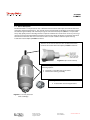
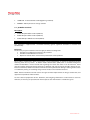
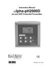
Instruction Manual ECFP21A1A1 Differential pH Sensor 1 ½ Inch NPT Mounting Threads Copyright © 2006 All rights reserved. Eutech Instruments Pte Ltd 68X216866 Rev 0 10/04 Blk 55, Ayer Rajah Crescent, #04-16/24 Singapore 139949 +65 6778 6876 +65 67730836 fax www.thermofisher.com TABLE OF CONTENTS TABLE OF CONTENTS.................................................................................................................................. 2 PREFACE....................................................................................................................................................... 3 SAFETY INFORMATION............................................................................................................................... 4 INTRODUCTION........................................................................................................................................... 5 1.1. General Information...............................................................................................................................................5 1.2. Intended use.............................................................................................................................................................5 1.3. Safety Instructions ..................................................................................................................................................6 1.4. Removal from Service / Correct Disposal of the Sensor.............................................................................6 PRODUCT DESCRIPTION............................................................................................................................. 7 2.1 Sensor Description .................................................................................................................................................7 2.2 Specifications ...........................................................................................................................................................8 INSTALLATION ............................................................................................................................................ 9 3.1 Wiring..........................................................................................................................................................................9 3.2 Mounting Hardware...............................................................................................................................................9 pH SENSOR MAINTENANCE...................................................................................................................... 13 4.1 Cleaning the pH Sensor Head.......................................................................................................................... 13 4.2 pH Sensor Refurbishment - Replacing the Salt Bridge and Reference Solution............................. 13 4.3 pH Sensor Troubleshooting ............................................................................................................................. 14 pH SENSOR SPARE PARTS & ACCESSORIES ............................................................................................ 15 5.1 Reference Cell Replacements .......................................................................................................................... 15 5.2 pH Buffer Standards ............................................................................................................................................ 16 WARRANTY................................................................................................................................................ 16 RETURN POLICY ........................................................................................................................................ 16 www.thermofisher.com PREFACE This instruction manual serves to explain the use of the ECFP21A1A1 1½ inch pH sensor and is written to cover as many applications as possible. Please do not hesitate to contact Eutech Instruments or an authorized representative with questions or concerns. The information presented in this instruction manual is subject to change without notice as improvements are made, and does not represent any commitment whatsoever on the part of Eutech Instruments. Eutech Instruments cannot accept any responsibility for damage or malfunction of the sensor due to improper use. Eutech Instruments Pte Ltd. All rights reserved www.thermofisher.com SAFETY INFORMATION The ECFP21A1A1 1½ inch pH sensor shall be installed and operated only in the manner specified. Only a skilled, trained or authorized person should carry out installation, setup and operation of the sensor system. Before using the sensor, make sure that the sensor cable is connected as specified. Failure to do so may result in permanent damage to the sensor or controller. Protection against electric shock will be achieved only by observance of the corresponding installation rules. Blk 55, Ayer Rajah Crescent, #04-16/24 Singapore 139949 +65 6778 6876 +65 67730836 fax www.thermofisher.com INTRODUCTION 1.1. General Information Thank you for purchasing the ECFP21A1A1 Differential pH Sensor. This industrial sensor has many enhanced features that offer superior performance in process applications: • Differential pH measurement technology minimizes susceptibility to ground loops. • A built in pre-amplifier eliminates high impedance wiring problems. • A replaceable heavy-duty quad junction salt bridge for extended life in severe applications. • A large reference reservoir filled with buffered solution minimizes the effects of dilution and extends the life of the reference electrode. • Easily refurbished in the field by replacing the salt bridge and reference solution, extending the life of the sensor. The product is designed for continuous use in industrial process applications and complies with safety regulations currently in force. Improper use could lead to hazards for the user or a third-party, and/or adverse effects to the plant or other equipment. Eutech Instruments does not accept any liability for damage that may arise if information in this manual is not followed. Therefore, the operating instructions and specifications must be read and understood by all persons involved in installation and operation of this equipment. This manual identifies safety instructions and additional information by means of the following symbols: This symbol draws attention to safety instructions and warnings of potential danger, which if neglected, could result in injury to persons and/or damage to property. This symbol identifies additional information and instructions, which if neglected, could lead to inefficient operation and possible loss of production. It is recommended that this manual be made accessible to everyone who may need it as a reference. Please contact Eutech Instruments or an authorized representative with any questions. 1.2. Intended use ECFP21A1A1 1½ inch pH sensor is designed to continuously measure pH and temperature in aqueous solutions in accordance with the technical product specifications in Section 2.2 of this manual. Any other use, or use not mentioned here, that is incompatible with the technical specifications is deemed inappropriate. The operator is solely responsible for any damage arising from such use. Other prerequisites for appropriate use include: • Observing the instructions, notes and requirements set out in this instruction manual. • Observing all local safety regulations. • Observing all warnings and cautions in the documentation regarding all products used in this measurement system, including the pH sensor, mounting hardware, analyzer electronics and cabling. • Observing the prescribed environmental and operational conditions. • Observing chemical compatibility with all wetted materials. Blk 55, Ayer Rajah Crescent, #04-16/24 Singapore 139949 +65 6778 6876 +65 67730836 fax www.thermofisher.com 1.3. Safety Instructions The ECFP21A1A1 1½ inch pH sensor should be installed and operated only by personnel familiar with the sensor and qualified for such work. A defective sensor should be returned to Eutech Instruments for repair or replacement. Contact Eutech Instruments to obtain a Return Goods Authorization (RGA) number. No modifications to the ECFP21A1A1 1½ inch pH sensor are allowed. The manufacturer/supplier accepts no responsibility for damage caused by unauthorized modifications. The risk is borne entirely by the user. 1.4. Removal from Service / Correct Disposal of the Sensor Removal from Service • • Disconnect the cable wiring from the controller terminal block. Remove the sensor from the mounting hardware. Correct Disposal of Unit • When the sensor is taken out of service, observe the local environmental regulations for correct disposal. www.thermofisher.com PRODUCT DESCRIPTION 2.1 Sensor Description The ECFP21A1A1 1½ inch pH sensor uses a differential measurement technique to maximize lifetime in continuous industrial applications. The ground rod and encapsulated preamplifier construction reduce the effects of ground loops and allow the pH signals to be transmitted up to 3,000 feet. A replaceable heavy-duty quad junction salt bridge makes it simple to refurbish the sensor when necessary. The large reference reservoir filled with buffered solution minimizes the effects of dilution and extends the life of the reference electrode. The wires in the sensor cable are color coded to allow for quick and easy installation into the Alpha pH2000D Controller. The wires in the sensor cable are color coded to match the terminal connection within the Alpha pH2000D Controller. Figure 2.2: pH sensor hook-up The sensor body has 1½ inch NPT threads for the following mounting options: ¾ ¾ Standard 1½ inch NPT pipe tee insertion. Immersion mounting assembly. Salt bridge: ¾ Protected for standard applications. Figure 2.1: 1½ inch pH Sensor with Salt Bridge Blk 55, Ayer Rajah Crescent, #04-16/24 Singapore 139949 +65 6778 6876 +65 67730836 fax www.thermofisher.com 2.2 Specifications Wetted Materials……………………………. Sensor Body - CPVC Salt Bridge Junctions - Kynar® pH Electrode - General glass Ground Rod - 316 Stainless Steel O-Ring Seals - Viton® (Consult factory for customized material construction) Operating Temperature…………………….. -5°C to 95°C (23°F to 203°F) Maximum Pressure…………………………. 100 psi @ 100°C (100 psi @ 212°F) Maximum Flow Rate………………………... 3 m/sec (10 ft/sec) Measuring Range…………………………… 0 to 14 pH Resolution……………………………………. 0.01 pH Standard Sensor Cable Length……………. 3 m (10 ft) Cable Wire Colors…………………………... White Wire (-5V) Black Wire (Ground) Red Wire (pH Electrode/Active(Measure)) Green Wire (Reference Electrode) Yellow Wire (Temperature/NTC 300) Drain/Shield (Earth) Maximum Transmission Distance…………. 914 m (3,000 ft) The sensor will arrive with a protective cap that keeps the sensor hydrated. For short-term storage, put several drops of Eutech Instruments’ storage solution on the absorbent material in the protective cap and replace the cap on the sensor. This keeps the process electrode and salt bridge moist. For extended storage, repeat the above short-term storage procedure every 2 to 4 weeks, depending on the surrounding environmental conditions. Make sure all wetted materials are compatible with process chemicals at operating temperatures and pressures. www.thermofisher.com INSTALLATION 3.1 Wiring Figure 3.1: pH Sensor Hook Up There are two different methods for electrical connection between the sensor and the pH controller; either direct or through a junction box. 3.1.1. Direct Connection 1. Use a watertight cord grip to insert the sensor cable into the Alpha pH2000D Controller. Conduit holes are found on the bottom of the Alpha pH2000D controller for this purpose. 2. Connect the sensor wires to the Alpha pH2000D controller as outlined in the controller manual. 3.1.2. Using a Junction Box (Indirect Connection) 1. Use a watertight cord grip to insert the sensor cable and the interconnect cable into the junction box that has a terminal strip designed to make the proper connections. 2. Connect both the sensor cable wires and the interconnect wires to the terminal strip. 3. Use a watertight cord grip to insert the sensor cable into the Alpha pH2000D Controller. Conduit holes are found on the bottom of the Alpha pH2000D controller for this purpose. 4. Connect the sensor wires to the Alpha pH2000D controller as outlined in the controller manual. Be sure that the wire colors of the sensor cable match those of the interconnect cable on either side of the terminal strip. Route the interconnect cable through metal conduit to minimize electrical noise that may interfere with the sensor signal. 3.2 Mounting Hardware Eutech Instruments’ short nose sensor (Fig 3.2) has insertion threads located closer to the sensing elements and is recommended for short branch tees (typically metal tees and SCH 40 plastic tees). www.thermofisher.com Save the protective cap and use it to keep electrodes moist whenever the sensor is removed from service. When taking a sensor out of storage, soak the sensor in a pH 7 buffer solution for 30 minutes before calibration. If the sensor does not calibrate, refer to Section 4 to review maintenance, refurbishment and troubleshooting options. The sensor should be positioned at least 15° up from horizontal. This will insure that entrained air does not form a pocket around the sensor head. DO NOT USE PIPE SEALANT. Pipe sealants may not provide adequate sealing or may react with different plastic materials. Use thread tape. DO NOT OVER TIGHTEN! Maximum torque: 65 lbs⋅inch (7 N⋅m) Figure 3.2: Short Nose Sensor Body 3.2.1. Pipe Tee Mounting Eutech Instruments’ distinct body type for its 1½ inch differential pH sensor ensure optimal positioning of the active pH sensor electrode in the process flow. Normally available pipe tees vary widely in construction dimensions. CPVC pipe tees are most generally available with schedule 80 walls. Stainless steel tees have thinner walls that change the final position of the sensor. Common mounting arrangements are shown for the short nose pH sensors. Recommended Tee Mounting Configurations Dimensions: IN (mm) Figure 3.3: Short Nose Sensor Mounted in Steel Tee or Schedule 40 PVC Tee Optimal electrode placement with minimum flow restriction www.thermofisher.com Detailed Pipe Tee Installation Instructions 1. Wiring: a. Route the cable – either through conduit or on a cable tray. b. Insert the sensor cable into the Alpha pH2000D controller through a watertight cord grip. Conduit holes are provided for the cord grip on the bottom of the Alpha pH2000D controller. c. Connect the sensor wires into the Alpha pH2000D sensor terminal block as shown in the Alpha pH2000D manual. 2. Calibrate: a. Power the Alpha pH2000D controller. b. Remove the protective cap from the sensor head and make sure moisture is present and that the salt bridge has not dried out. If the protective cap is dry, the sensor should be hydrated in tap water for at least 1 hour prior to calibration. c. Calibrate the pH sensor as explained in the Alpha pH2000D manual. It is recommended to use a 2-point buffer calibration on installation of the sensor. Subsequent calibrations should be scheduled based on process demands. d. If measurement response time is slow or if the sensor will not calibrate, refer to Section 4 for maintenance, refurbishment and troubleshooting suggestions. 3. Mount: a. Apply PTFE tape to the sensor body threads. b. Insert the sensor into the tee and slowly turn clockwise until secure. Tighten the sensor with a wrench until snug to prevent leaking. Be sure the pipe remains full when the sensors are installed. 3.2.2. Immersion Mounting For immersion mounting applications the sensor is connected to a 1½ inch extension pipe to protect the cable from damage and to reduce the possibility of leaks that may damage the sensor. Figure 3.5: Immersion mounting assembly www.thermofisher.com Detailed Insertion Mount Installation Instructions 1. Wiring: c. Route the sensor cable through the 1.5 inch extension pipe. d. Apply PTFE tape to the sensor threads. e. Attach the sensor to the 1.5 inch NPT coupling by turning the sensor in a clockwise direction until secure. f. Either route the cable directly to the Alpha pH2000D or splice the wires in a junction box and use an extension cable. g. Insert the cable into the Alpha pH2000D controller through a watertight cord grip. Conduit holes are provided for the cord grip on the bottom of the Alpha pH2000D controller. h. Connect the sensor wires into the Alpha pH2000D sensor terminal block as shown in the Alpha pH2000D manual. 2. Calibrate: a. Power the Alpha pH2000D controller. b. Remove the protective cap from the sensor head and make sure moisture is present and that the salt bridge has not dried out. If the protective cap is dry, the sensor should be hydrated in tap water for at least 1 hour prior to calibration. c. Calibrate the pH sensor as explained in the Alpha pH2000D manual. It is recommended to use a 2-point buffer calibration on installation of the sensor. Subsequent calibrations should be scheduled based on process demands. d. If measurement response time is slow or if the sensor will not calibrate, refer to Section 4 for maintenance, refurbishment and troubleshooting suggestions. 3. Mount: a. Secure the pipe assembly so that the sensor is fully immersed in the process. Be sure that the wire colors of the sensor cable match those of the interconnect cable on either side of the terminal strip. Do not route the interconnect cable conduit where there are AC or DC power cables which create electrical noise that may interfere with the sensor signal. Route the interconnect cable through metal conduit to minimize electrical noise that may interfere with the sensor signal. www.thermofisher.com pH SENSOR MAINTENANCE 4.1 Cleaning the pH Sensor Head 4.1.1 In order to maintain an accurate measurement value, the sensor will need occasional maintenance. The maintenance interval will be dictated by the process in which it is installed. The harsher the process, the more often the sensor will require maintenance. Regular maintenance will yield a longer sensor life. 4.1.2 The sensor cleaning procedure is as follows: 4.1.2.1 Remove sensor from service and rinse or spray it with warm water to remove heavy deposits. 4.1.2.2 Soak the sensor in a container of hot detergent water for one hour. Do not use detergents that contain oily skin softeners like aloe or lanolin that can coat the glass electrode. Alconox® and Dawn™ dishwashing liquid work well. 4.1.2.3 Use a soft-bristled brush, such as a soft toothbrush, and hot detergent water to scrub the entire electrode end of the sensor, being careful not to scratch or break the glass electrode. 4.1.2.4 Rinse the electrode end with clean warm water. 4.1.2.5 If deposits are still present on glass electrode repeat steps 2 and 3. In the case of lime or other mineral deposits a weak solution (about 0.1 M) of hydrochloric acid may be used. In some cases, a dilute solution (about 10:1) of water and chlorine bleach or a solution of water and EDTA may also work. Stubborn oil or grease deposits may require cleaning with a solvent such as acetone or alcohol. Protein deposits may be cleaned with a pepsin-based cleaning solution. Bacterial or mold growth may be removed with dilute chlorine bleach. Caution: Ensure that dangerous chemical reactions will not occur between process deposits and cleaning solutions. Compounds of cyanide and hydrochloric acid will react and pose health risks. Cyanide is often used in electroplating and in gold refining. If in doubt about potential chemical reactions, check with a chemist before cleaning. 4.1.3 Before returning the sensor to service, allow it to soak in water or buffer at ambient temperature for about an hour to restabilize the pH electrode and the salt bridge. 4.1.4 After cleaning the sensor, calibrate sensor per instructions in the Alpha pH2000D controller manual. 4.1.5 Reinstall sensor in process. 4.2 pH Sensor Refurbishment – Replacing the Salt Bridge and Reference Solution 4.2.1 If the sensor head has been cleaned (see section 4.1.2) and calibration cannot be achieved, replace the salt bridge and reference solution. 4.2.2 Hold the sensor firmly with the electrode tip facing upwards. Remove the existing salt bridge by using a 15/16 wrench (24mm) and turning it counterclockwise. Dispose of the salt bridge using an approved method. 4.2.3 Pour out the old reference solution. Rinse the reservoir with distilled or de-ionized water. www.thermofisher.com 4.2.4 Slowly fill the reservoir with 7pH Standard Cell Filling Solution so the solution just covers the reference O-ring. Do not over fill. Overfilling will lead to excessive pressures that will affect the junction potentials of the reference. 4.2.5 Slowly screw the new salt bridge clockwise onto the sensor head until secure. Tighten the salt bridge with a 15/16 wrench (24mm) until snug. Do not over tighten. Maximum torque: 10 lbs⋅in (1.13 N⋅m) 4.2.6 After replacing the salt bridge and reference solution, calibrate the sensor according to the instructions in the Alpha pH2000D controller manual. If after cleaning and refurbishment sensors still have slow responses, low measurement slopes or are seriously abraded or scratched they must be replaced. 4.3 pH Sensor Troubleshooting General Inspection If the sensor is not providing reasonable signals to the analyzer, check the following: 1. Inspect the integrity of the glass electrodes. If the electrode is broken, replace the sensor. 2. Inspect the integrity of the salt bridge junctions. Be sure that they are clean and moist. If the salt bridge has been allowed to dry out it may be necessary to replace the salt bridge and filling solution. 3. Inspect the sensor cable for damage to the outer jacket. Any cuts or kinks may damage signal connections. 4. Inspect terminal block connections to be sure wires are not corroded or loose. 5. Make sure all sensor wires are connected to the correct places on the analyzer terminal block. Depending on the analyzer, some terminal block jumpers may be required and it is common to put those jumpers in the wrong place. 6. The sensor electrodes should be immersed in a solution of known pH. 7. Establish that the analyzer electronics are working correctly by verifying operation with another sensor. Note: Any new sensor that has been in storage for more than a few days should be soaked in tap water or a solution of known pH for at least 30 minutes to before reviewing the span and offset performance. Note: The electrodes of any pH sensor in storage must be kept moist at all times. Protective caps should be filled with storage solution for best performance. The protective cap should be placed securely over the sensor head. If the sensor passes the general inspection, there are four basic tests that can verify the temperature measurement, the pH offset, the pH Span and the pH span on sensor power. If the sensor passes these tests it should be ready for service. www.thermofisher.com Temperature Span Disconnect the BLACK and YELLOW sensor wires from the analyzer. Use an ohmmeter to measure the resistance between the BLACK and YELLOW wires. The meter should measure a resistance corresponding to the sensor temperature as outlined in the following table. Sensor Temperature 5C 15C 25C 35C 45C Thermistor Resistance 630 Ω 430 Ω 300 Ω 215 Ω 155 Ω If the measured resistance is within 10 to 20 ohms of the expected value, the element should be satisfactory. If not, please consult the factory. pH Offset Test 1. Disconnect the RED and GREEN sensor wires from the analyzer terminal block while leaving the other wires connected. Connect the (+) lead of a millivolt meter to the RED wire and the (-) lead of the millivolt meter to the GREEN wire. 2. Put the sensor in 7 pH buffer. Stir the sensor for 10 to 15 seconds and then allow the sensor to stabilize in solution for about 2 minutes. The meter should read 0.0mV +/- 50 mV. If the reading is higher or lower than specified, replace the salt bridge and filling solution and try again. If on the second attempt the offset does not meet specification, replace the sensor. pH Span Test If the RED and GREEN wires have already been disconnected to run the offset test, skip step 1. 1. Disconnect the RED and GREEN sensor wires from the analyzer terminal block while leaving the other wires connected. Connect the (+) lead of a millivolt meter to the RED wire and the (-) lead of the millivolt meter to the GREEN wire. 2. Rinse the sensor in clean water. Put the sensor in 4 pH buffer. Stir the sensor for 10 to 15 seconds and then allow the sensor to stabilize in solution for about 2 minutes. The meter should read a change of at least 150mV from the offset reading. For example, if the offset is +20mV the reading in 4 pH buffer should be at least 170mV. After testing offset and span, the RED and GREEN wires should be reconnected to the analyzer terminal block. Sensor Power Test If the sensor does not respond with any reasonable millivolt signal in the offset and span tests, it may be worthwhile to verify that power is being supplied to the sensor from the analyzer. To do this, connect a voltmeter from the BLACK lead to the WHITE lead (It is not necessary to disconnect the wires from the terminal block). The meter should read –5 VDC +/- 0.3 VDC. If the voltage is low, disconnect the white wire from the terminal block and measure the voltage on the terminal block. If the voltage comes back into specification there is a defect in the sensor that is loading down the analyzer. If the voltage remains low then the analyzer may be defective. If the sensor passes the temperature, offset, span and power tests but the analyzer is not displaying the correct values, the analyzer may be defective. pH SENSOR SPARE PARTS & ACCESSORIES 5.1 Reference Cell Replacements Description • 01X211270 - Reference Cell Filling Solution (500 ml) www.thermofisher.com • 15X403101 - Protected CPVC Salt Bridge(O-ring included) • ECRE005 – 480 ml pH Sensor Storage Solution 5.2 pH Buffer Standards Description • EC-BU-4BT pH 4 Buffer Standard (480 ml) • EC-BU-7BT pH 7 Buffer Standard (480 ml) • EC-BU-10BT pH 10 Buffer Standard (480 ml) WARRANTY This electrode is supplied with a six-month warranty against significant deviations in material and workmanship. Exclusions The warranty on your instrument shall not apply to defects resulting from: Improper or inadequate maintenance by customer Unauthorised modification or misuse Operation outside of the environment specifications of the products RETURN POLICY Please obtain authorisation from our Customer Service Department or authorised distributor before returning items for any reason. A “Return Goods Authorisation” (RGA) form is available through our authorised distributor. Please include data regarding the reason the items are to be returned. Items must be carefully packed to prevent damage in shipment and insured against possible damage or loss. Eutech Instruments/ Oakton Instruments will not be held responsible for damage resulting from careless or insufficient packing. A restocking charge will be made on all unauthorised returns. NOTE: Eutech Instruments Pte Ltd reserves the right to make improvements in design, construction, and appearance of products without notice. As of the date of preparation of this document, the foregoing information is believed to be accurate. However, no warranty or representation with respect to such information is intended or given. www.thermofisher.com