1
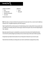
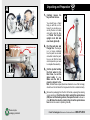
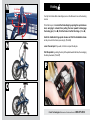
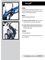
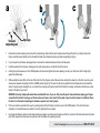
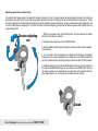
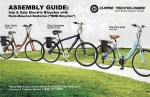
Please Refer to your Owner’s Manual for Detailed Setup Instructions IZIP VIA URBANO ASSEMBLY GUIDE Technical & Customer Service: 1-800-377-4532 Assembly Tools Included in your parts box: • • • • Pedals Quick release skewer Toolkit (4+5mm combo wrench) Touch-up Paint Helpful Tools: • • Scissors Bicycle grease Assembly will take about an hour Note: When working on your bicycle as instructed by this guide, please refer to the torque values chart in your owner’s manual for detailed torque requirements. Under- or over-tightened components may loosen or break, causing a fall. Steps in this guide that call for the use of bicycle grease do so in the interest of keeping your bicycle in working condition for as long as possible. Grease is not absolutely vital to the assembly of this product, but failure to apply it as directed could cause parts to seize over time and irreparably damage the frame or components. Because bicycle parts tend to be greasy, it is recommended that you lay down a tarp or sheet to protect your floor if assembling the bike indoors. It is best to remove the protective packaging during the assembly process only as needed, leaving some intact to protect the bike during assembly. During assembly it may be helpful to reference the photos on the cover of this guide and on the bicycle box if you are unsure of any steps. Please take the time to read the battery care and storage section of your manual for useful information on prolonging the life of your battery. Unpacking and Preparation A 1. Carefully remove the bicycle from the box. You should have a friend help you with this, as it is heavy. If you are alone, you can lay the box on its side and gently slide the bike out. Stand the bicycle B C upright on its fork and rear wheel. (photo A). Tab (push to unlock QR lever) Swing QR lever open Hinge 2. Find the parts box and charger box. The charger is in a brown cardboard box, the parts box is small and white. Inside the parts box you will find the tools and components you need to complete this assembly. 3. Cut the zip-ties holding the front wheel to the bike frame, then set the wheel aside for now. Make sure the fork is properly aligned to the bike; the disc brake caliper (black box attached to one of the fork legs) Steering column should be on the left side of the bicycle when the fork is rotated correctly. 4. Please recycle packaging materials! Remove the packaging from the front of the bike, exposing the steering column and hinge. Push the silver tab to unlock the quick-release (QR) lever on the steering column, then open the lever as shown in photo B. Raise the steering column, then close the quick-release lever to lock the column in position (photo C). Currie Technologies Technical and Customer Service 1-800-377-4532 Handlebars D E Handlebar/stem assembly 5. Open the quick-release lever on top of the steering column (photo D), then insert the handlebar/stem assembly into the column (photo E). For your safety, be sure the stem is inserted past the “minimum insertion” line. By sliding the stem up or down, you can adjust the height of the handlebars to find the most comfortable riding position once assembly is complete. Close the steering column quick-release lever. If the quick-release lever does not provide a fair amount of resistance against being closed, or if the handlebars do not feel securely clamped after closing the lever completely, you will need to re-adjust the lever, referring to the appendix to this guide discussing quick release clamps. You can tell if the handlebars are properly secure by holding the fork steady and trying to twist the handlebars out of alignment. If the handlebars are able to turn, you must adjust the quick release properly or risk having the handlebars turn away from you while riding, likely causing a fall. Insert stem into steering column Open QR F 1. Insert seatpost into seat tube Seatpost 6. Unpack the saddle and seatpost. Open the quick-release lever on the bicycle’s seat tube, then insert the seatpost into the seat tube. To make the next steps of this assembly easier, the saddle should be set about level with the handlebars. Close the saddle quick release, referring to the appendix to this guide on quick release clamps. (Photo F). 7. Flip the bicycle over, balancing it on its handlebars and saddle. Be careful that you don’t damage the handlebar-mounted controls. (Photo G). Currie Technologies Technical and Customer Service 1-800-377-4532 2. Close QR lever H G Dropout protector (remove) Front Wheel Brake caliper 8. Remove the black plastic dropout protector from the fork (Photo H). Remove the two black plastic caps from the front wheel’s hub. 9. Find the quick-release skewer in your parts box (Photo I). 10.Refer to diagram J for assistance with this step: I Quick-release skewer Tension adjusting nut Remove the tension adjusting nut and one spring from the quickrelease skewer, taking care not to lose either of the small springs. Push the skewer through the front hub, starting from the side of the wheel with the brake rotor. Replace the spring and nut. Leave the nut loose for now, about two turns in. 11.Drop the front wheel into the fork, guiding the brake rotor into the Springs slot in the brake caliper. Close the wheel’s quick-release, tightening the skewer’s end nut to adjust preload as necessary to make the wheel secure. Refer to the appendix to this guide discussing wheel quick releases for more information on the use and adjustment of quick-release levers. It is vital to your safety that you understand and properly secure this lever! J Currie Technologies Technical and Customer Service 1-800-377-4532 Pedals L 12.Find the pedals in your parts box. Grease the threads and thread them securely Tighten pedals into the crank arms using a 15mm open-end wrench. Note that the pedals have opposite thread directions and must go on a specific side of the bicycle. The pedal meant for the drive-side (the side of the bicycle with the chain and gears) has a standard thread, which is tightened clockwise. The non-drive-side pedal has a reverse, non-standard thread. It must be turned counter-clockwise to be screwed in. The pedals are marked ‘R’ and ‘L’ for “Right” and “Left.” 13.Turn the bike right-side-up, using the kickstand to keep it upright. 14.Adjust your front and rear brakes. Your brakes may not be fully adjusted from the factory; refer to your owner’s manual for detailed instructions on brake adjustment or consult a professional bike mechanic if you are not comfortable making these adjustments yourself. Do not attempt to ride your bicycle without properly adjusting the brakes! 15.Adjust your shifter and derailleur, referring to the owner’s manual for full instructions. Riding your bicycle without properly adjusting the drivetrain can cause irreparable damage! Consult a professional bike mechanic if you are not comfortable making these adjustments yourself Currie Technologies Technical and Customer Service 1-800-377-4532 M 3. Pull pin to release hinge Folding 1. Open lever 2. Swing Your Izip Via Urbano folds at two hinges; one on the frame and one on the steering column. To fold the bicycle, first unlock the frame hinge by opening the quick release lever, swinging it outward, then pulling the lever upward to disengage the locking pin (Photo M). Fold the frame in half at this hinge. (Photo N) Undo the handlebar hinge quick release and fold the handlebars down N so they lie next to the frame (see step 4). (Photo O) Lower the seat post if you wish, to further compact the bicycle. Fold the pedals by pushing the body of the pedal towards the bike, then swinging the body downward. (Photo P) P O Currie Technologies Technical and Customer Service 1-800-377-4532 Operation 1. Flip the rear power switch to the ON position, then press to turn on the bicycle. • After pressing ‘Power’, all eight meter lights will flash in sequence, indicating that the bike is ready to ride. 2. The lights indicate remaining charge. • The battery gauge provides five indications of battery level. 3. • When the battery is depleted to the point of automatic shutoff, the lowest gauge light will blink indicating the need to recharge immediately. Of course, the bicycle can still be ridden while the system is turned off. • Due to the way the battery gauge measures charge, the indicator lights may fluctuate while riding based on the motor’s current load. • The best indication of remaining battery life is to check the battery level gauge LEDs after reaching cruising speed on a smooth, flat, straight road. This will allow the battery voltage to stabilize and will give a much more accurate reading. Q Power switch location 2 The button controls motor assist power • The PAS system provides three assist levels, which can be cycled between using the ‘Assist +/-’ button. • Each level of assist corresponds to a maximum motor speed; at level 3, the motor runs at full power. • The system defaults to the lowest assist level at startup. • The motor will activate when the system senses the rider pedaling. It is not possible to activate the motor without turning the cranks. Currie Technologies Technical and Customer Service 1-800-377-4532 3 1 The Via Urbano uses ‘PAS’ Technology: P Battery Charger port location Charging The Via Urbano battery can be charged while inside the bike, or it can be removed and charged separately. The charger port is located on the right side of the frame, near the center folding hinge. (Photo P) Removal To remove the battery pack from the frame: R 1. Fold the frame in half at the center hinge. This will expose the battery Battery release button terminals; be careful not to cross them with your fingers or jewelry. 2. Press the battery release button while pulling the battery out of the frame. The battery fits tightly into the frame to prevent vibration, so it may initially be difficult to remove. Battery Installation To re-insert the battery pack: Push the battery back into the frame, making sure the release button lines up and “pops” through its hole Currie Technologies Technical and Customer Service 1-800-377-4532 Appendix: Quick Release Levers Many Izip and Ezip bicycle models use quick release (QR) levers to facilitate common tasks such as front wheel removal and seat height adjustment. When properly adjusted, quick release levers are both safe and convenient, but you must understand and apply the correct technique to adjust them properly before riding your bicycle to prevent serious injury or death from a fall. Quick release levers use a cam action to clamp the wheel or other components in place. Because of their adjustable nature, it is critical that you understand how they work, how to use them properly, and how much force you need to apply to secure them. Warning: The full force of the cam action is needed to clamp the wheel securely. Holding the nut with one hand and turning the lever like a wing nut is NOT a safe or effective way to close a quick release and will not clamp the wheel or other components safely. QUICK RELEASE USAGE Riding with an improperly adjusted wheel quick release can allow the wheel to wobble or fall off the bicycle, which can cause serious injury or death. Therefore, it is essential that you: 1. Ask your dealer or a local bike shop to help you make sure you know how to install and remove your wheels safely. 2. Understand and apply the correct technique for clamping your wheel in place with a quick release. 3. Each time, before you ride the bike, check that the wheel is securely clamped. Installing a quick release front wheel In a quick release system, the wheel hub is clamped in place by the force of the quick release cam pushing against one dropout and pulling the tension adjusting nut, by way of the skewer, against the other dropout. The amount of clamping force is controlled by the tension adjusting nut. Turning the tension adjusting nut clockwise while keeping the cam lever from rotating increases clamping force; turning it counterclockwise while keeping the cam lever from rotating reduces clamping force. Less than half a turn of the tension adjusting nut can make the difference between safe clamping force and unsafe clamping force. Currie Technologies Technical and Customer Service 1-800-377-4532 a Tension adjusting nut c b Springs closed open 1. Remove the tension adjusting nut and one of the small springs, then slide the quick release skewer through the hub. If your bicycle has a disc brake, insert the skewer starting on the side with the brake rotor. Replace the spring and tension adjusting nut (fig a). 2. If your bicycle has rim brakes, disengage them to increase the clearance between the tire and brake pads. 3. Install the wheel into the dropouts, making sure the quick release lever is on the left side of the bicycle. 4. Holding the quick release lever in the OPEN position with one hand, tighten the tension adjusting nut with your other hand until it is finger tight against the fork dropout. 5. While pushing the wheel firmly to the top of the slots in the fork dropouts, and at the same time centering the wheel rim in the fork, move the quickrelease lever upwards and swing it into the CLOSED position (fig b & c) The lever should now be parallel to the fork blade and curved toward the wheel. To apply enough clamping force, you should have to wrap your fingers around the fork blade for leverage, and the lever should leave a clear imprint in the palm of your hand. WARNING: Securely clamping the wheel takes considerable force. If you can fully close the quick release without wrapping your fingers around the fork blade for leverage, and the lever does not leave a clear imprint in the palm of your hand, the tension is insufficient. Open the lever; turn the tension adjusting nut clockwise a quarter turn; then try again. 6. If the lever cannot be pushed all the way to a position parallel to the fork blade, return the lever to the OPEN position. Then turn the tension adjusting nut counterclockwise one-quarter turn and try tightening the lever again. 7. Re-engage the brake to restore correct brake pad-to-rim clearance; spin the wheel to make sure that it is centered in the frame and clears the brake pads; then squeeze the brake lever and make sure that the brakes are operating correctly. Currie Technologies Technical and Customer Service 1-800-377-4532 Adjusting a quick release seatpost clamp In a seatpost quick release system, the seatpost is clamped in place by the force of the quick release cam pushing against one side of the clamp and pulling the tension adjusting nut, by way of the skewer, against the other. The amount of clamping force is controlled by the tension adjusting nut. Turning the tension adjusting nut clockwise while keeping the cam lever from rotating increases clamping force; turning it counterclockwise while keeping the cam lever from rotating reduces clamping force. Less than half a turn of the tension adjusting nut can make the difference between safe clamping force and unsafe clamping force. Tension adjusting nut 1. With the quick release clamp in the OPEN position, insert the seatpost, with saddle attached, into the bicycle’s seat tube. 2. Swing the quick release lever into the CLOSED position. 3. Grab the saddle with both hands and attempt to rotate it (and thus rotate the seatpost in the seat tube). 4. If you are able to force the seatpost out of alignment with the frame, the seatpost clamp needs to be adjusted. Holding the quick release lever in the OPEN position with one hand, tighten the tension adjusting nut with your other hand about 1/2 turn clockwise. open 5. Attempt to swing the lever into the CLOSED position. If the lever cannot be pushed all the way to the CLOSED position (figure b), return the lever to the OPEN position, then turn the tension adjusting nut counterclockwise one-quarter turn and try tightening the lever again. Repeat steps 3, 4 & 5 until proper quick release tension is achieved. Closed Currie Technologies Technical and Customer Service 1-800-377-4532 Before your first ride... • Remove all remaining packaging on the bike. • • Check the operation of your front and rear brakes by pushing the bike forward and operating the brake levers. Check the tightness of all nuts and bolts, especially the front and rear wheel nuts, the stem bolts, and the bolts securing the brake levers and • • shifters to the handlebars. Make sure your front wheel is secure in the frame. Refer to the appendix to this guide for more information on quick release systems. Make sure your tires are filled to the pressure recommended on the sidewall. Over- or under-inflated tires can blow off the rim and cause a fall. We recommend using a bicycle pump with pressure gauge. Basic Troubleshooting Refer to owner’s manual for detailed troubleshooting chart Bike won’t turn on (no lights on handlebar control box) Check that the physical switch (located on the right-side of the bicycle near the center hinge) is in the ON position before pressing the control box ON/OFF button. Battery may not be charged Brakes rub when riding Re-adjust brakes, referring to owner’s manual Gears/chain make clicking or grinding noises while riding Re-adjust drivetrain, referring to owner’s manual Can someone help me with...? Call the Currie Technologies technical and customer service department at 1-800-377-4532 Currie Technologies Technical and Customer Service 1-800-377-4532 Notes: Notes: 9453 Owensmouth Ave, Chatsworth, CA 91311 Phone: +1 800.377.4532 Fax: +1 818.734.8199 www.currietech.com