1
./
,
,,
i
/
I
-c
"","-
c>
"
.1·1
,"
CROM~CO
BD-20
Installation Procedure
i
i
/'
.~
•
i
1
,
,jj.. ~'
I
~,-~~
--'"
(
CROMEMCO, INC.
280 Bernardo Avenue
Mountain View, CA 94043
Part No. 023-6042
March 1983
Copyright © 1983
CROMEMCO, INC.
All Rights Reserved
.
/
{
to·
I
.
(;
"\\
This manual was produced using a Cromemco
System Three computer wi th a Cromemco HDD-22
Hard Disk Storage System running under the
Cromemco Cromix™
Operating System.
The text
was edi ted with the Cromemco Cromix Scr een
Editor.
The edited text was proofread by the
Cromemco SpellMaster™
Program and formatted by the Cromemco Word processing System
Formatter II.
Camera-ready copy was printed
on a Cromemco 3355B printer.
,
8D-20 INSTALLATION PROCEDURE
mIS PROCEDURE IS ONLY TO BE PERFORMED BY AN
AUTHORIZED CROMEMCO DEALER OR REPAIR FACILITY.
BEFORE PROCEEDING, MAKE SURE THAT YOU ARE
USING THE COOS OPERATING SYSTEM VERSION 2.56
OR HIGHER, THE CROMIX OPERATING SYSTEM VERSION
11.16 OR HIGHER, OR THE 68000 CROMIX OPERATING
SYSTEM VERSION 20.14 OR HIGHER.
SEVERE DAMAGE TO THE 80-20 DRIVE MAY RESULT IF
OLDER VERSIONS OF THE OPERATING
THIS DAMAGE IS NOT COYERED BY THE
CROMEMCQ LIMITED WARRANTY.
YOU USE
SYSTEM.
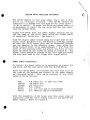
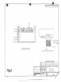
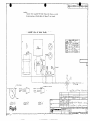
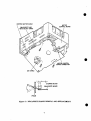
The HD-20 is designed to operate in a
Two or Three.
Prior to installation,
drive is set up to respond as drive O.
should be on the left set of the drive
viewed form the rear, see Figure 1).
Cromemco System
verify that the
The blue jumper
select pins (as
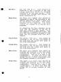
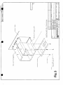
Signal Cable Connection
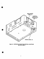
The 36 conductor signal cable is connected between the
HD-20 and the WDI-II.
The first step in the
installation of the HD-20 is the co nnecti on of the
signal cable to the HD-20. This must be done before the
drive is mounted in the system.
Looking at the rear of
the drive with the heat sink on the left, the cable is
connected with the index strip to the right. See Figure
2.
You are now ready to mount the HD-20.
Refer to section
of the following instructions which is appropriate to
your system.
1
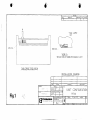
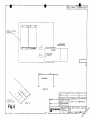
System Two and Z2-D Mounting Procedure
The HD-20 mounts just below the two 5" floppy disk
drives in the System Two.
Each of the two flopPY disk
drives is held in its metal frame by means of 6-32
screws.
Remove th€! two bottom retaining screws from
each drive and then reinstall them so that the mounting
plate for the HD-20 is attached to the bottom of the two
floppy disk support housings.
Refer to Figure 3.
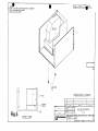
Plug the HD-20 power cord into the plug on the HD-20.
This connector is designed so that it can only be
connected one way.
Now slide the HD-20 onto the HD-20
mounting plate.
Refer to Figure 4.
Power Cable Connection
To install the power cable it is necessary to remove the
top cover and the rear panel from the System Two.
Route the HD-20 power cord along the same pa th as the
floppy disk power cord and connect to the power~upply
as indicated below.
This cable consists of six color
coded wires as follows:
Red
Yellow
Orange
Black
Brown
white
+ 8 volts d.c. (3 amp line fuse)
-16 volts d.c.
+16 volts d.c.
d.c. common
a.c. 115 volt tap on transformer
a.c. Neutral tap on transformer
-~
with the exception of the brown wire this color code is
consistent with the color coding used for the System Two
power supply.
Red Wire:
Th e r e d ( + 8 v d. c • )
wire s h 0 u 1 d b e
connected to the + terminal on either of
the 130,000 mfd capacitors.
This
terminal will already have one or more
red wires connected to it.
Black Wire:
The black (d.c. common) wire should be
connected to one of the 29000 mfd
capacitor terminals where a black wire is
already connected.
2
•
In connecting the four remalnlng wire s
note that the connector on the end of
each wire contains a male adaptor.
Once
the connector is plugged onto a post, the
wire that was originally plugged to that
post can be plugged onto the mail
adaptor.
Yellow Wire:
wire should be
The yellow (-16v d. c. )
connected to the -16 volt fuse holder on
the side with the yellow wire going to
the S-IOO motherboard.
Orange Wire:
The orange (+16v d.c.)
wire should be
connected to the +16 volt fuse holder on
the side with the orange wire going to
the S-IOO motherboard.
white Wire:
The whi te (a. c. neutr al) wire should be
attached and soldered to the main power
transformer primary pin 5 on 8 tap
transformers.
(Use pin 4 on older 6 tap
transformers.)
A black wire from the
system fan and a whi te transformer wire
are already attached to this point.
Brown Wire:
The brown (a.c. l15v) wire should be
attached and soldered to the main power
transformer primary pin 7 on 8 tap
transformers.
(Use pin 6 on older 6 tap
transformers.)
A black wire from the
system fan is already attached to this
point.
This completes theSyst ern
harness for the HD-20.
Two wiring
of
the
power
Connect the signal cabl e coming f rom the HD-20 to the
WDI-II being careful that the cable marking stripe is
positioned in the manner indicated on the WDI-II.
3
'\.
\
'"
..
,,~
System Three Mounting Procedure
The HD-20 mounts in the area where the C and D disk
drive is normally located.
The HD-20 cannot be
installed in a system with two disk drives (four slots A, B, C, and D). To mount the drive and power cable it
is necessary to remove the top cover and the rear panel
from the System Three.
Orient the HD-20 with the power supply cooling fin up
and the rear of the drive (part where the signal cable
is connected) facing you. See Figure 5.
With the signal cable routed along the right side of the
drive, slide the drive into the mounting area far enough
so that the HD-20 power plug can be connected through
the top opening in the mounting frame.
NOW, slide the
HO-20 forward until it is approximately 1 1/4" from the
front of the mounting frame and attach the drive at that
point by means of two screws as shown in Figure 5. The
signal cable should be routed to the card cage following
the same path used by the floppy disk signal cable.
Power Cable Connection
To install the power cable it is necessary to remove the
top cover and the rear panel from the System Three.
Route the HD-20 power cord between the heat sink fins to
the rear of the system and connect to the power supply
as indicated below.
This cable consists of six color
coded wires as follows:
Red
Yellow
Orange
Black
Brown
White
+ 8 volts d.c. (3 amp line fuse)
-16 volts d.c.
+16 volts d.c.
d.c. common
a.c. 115 volt tap on transformer
a.c. Neutral tap on transformer
with the exception of the brown wire this color code is
consistent with the color coding used for the System Two
power supply. Refer to Figure 6.
4
~.
\\
•
Red wire:
The red {+8v d.c.}
wire should be
connected to the + terminal on the very
large capacitor which is mounted
vertically on the back panel.
This
terminal will already have several red
wires connected to it.
Black Wire:
The black (d.c. common) wire should be
connected to one of the terminals of the
smaller capacitors to which a black wire
is currently attached.
The other
terminal of the capacitor will have
e i t her an 0 ran g e 0 r a y ell ow wi r e
attached.
In connecting the four rema~n~ng wires
note that the connector on the end of
each wire contains a male adaptor.
Once
the connector is plugged onto a post, the
wire that was originally plugged to that
post can be plugged onto the mail
adaptor.
Yellow Wire:
The yellow (-16v d.c.)
wire should be
connected to the -16 volt fuse hol~er on
the side with the yellow wire going to
the 8-100 motherboard.
Orange wire:
The orange (+16v d.c.)
wire should be
connected to the +16 volt fuse holder on
the side wi th the orange wi re going to
the 5-100 motherboard.
White Wire:
The white (a.c. neutral) wire should be
attached and soldered to the main power
transformer primary pin 5 on 8 tap
transformers.
(Use pin 4 on older 6 tap
transformers.)
A black wire from the
system fan and a whi te transformer wire
are already attached to this point.
Brown Wire:
The brown (a.c. 11Sv) wire should be·
attached and soldered to the main power
transformer primary pin 7 on 8 tap
transformers.
(Use pin 6 on older 6 tap
t ran s for mer s • )
A b I a c k wi r e f r om th e
system fan is already attached to this
point.
ce
5
This completes the System Three wiring
harness for the HD-20.
of
the
power
Connect the signal cabl e coming f rom the HD-20 to the
WDI-II being careful that the cable marking stripe is
positioned in the manner indicated on the WDI-II.
6
_.
i-
~'-
<TO
REvISIONS
r
r DAAfTSMAN I
I
DICSCA, .. noN
r APPROVAl.
f
O .... lf
r
T
A
,-
n
-- BLUE
CAP
I
-< "7
_~lllllllill
\
I
RED LED
/
RED
LED-~
JUMPER
~:::J
VIEW A
TOP-SIDE PCB NOT SHOWN FOR DR,t..WING CLARITY
DISK DRIVE END VI EW
1NSTALLATION
PART NO
ITEM
MA'fEAI .... L
--
--
OeoSCMIPlLON
DAlE
APPROVAl-S
(~ \.jo
ilooIANUFAC1UREH
TIH.£:
UNIT CON FIGURATION
DE5lUNlf\
DRAfTSMAN
DRAWING
2 _Z"" i!Z
FINISri
Fig.1
I
:~ '
t. I\
--,
( - .
. {
---
HD-20
CH~CKE.A
[3 ~~~~~~~.~
UNlESS OTH£AW'Sf: Sf'£C.fIEQ
OlMENS.lONS ARt' IN IN"CH~S
TOLERANCES AAt:
FRACYIOhiS OE:C~MALS ANGLES
± -
Xl(
t --
xX)IC:t -
!:
~
S.ZiE
.. .. ODUCT
I
I
OWG.l'r'''E
'DNUM8I:A
M.V
B
SCALE
T-T
TSHHl
I
OF
I
",~"'"QV'" ~
O
w7Jl
~
~
0
--m1u
c'
I~Df)(
DISK DRIVE END VIEW
5TRIPf
VIEW-A
(TOP-SIOf PCB ~OT SHowN fOR DRAWl ~G CLARln)
INSTALLATION DRAWING
OAt(
""... Ylill.Al
I
"llit
OE51(i,N(~
Fig. 2
_ _ _ _ _ _ _ _ _ _ _- - - - - - - " 0
D-IL.UJ~"""'"
DATA CABLE
CONNECTION
rf1C Acl2-25-8
UtlCKIi,ll
[3~~~~~~~...
..
~:1:lE~:,~~~~A ~'~~ ~~~~~F;kD
,.OUIlI"''''C£:O "''''l
11'1 ....(;1.011/$ Otc,M"lS Jil"'(iU5
'IX
t
.",I(f
t
I
Sou
c
$C.-r,LE
I
I'IlIODUl;;l
I
tl"'"
SH~£1
tH'f'
'LI NUMIIU'
I
flU_
~
~I
~
<
~
o
t-
;z--.,
,~
cs
~
2
0I
N
~
N
-<>d"'J
u
~
t
l-
2
~
lJ.
~
iii
n
"2
1i
~
~
"2
<::J
~
z
~
!ooI ~
~! ~
,.
!~ ~
j: ~
;~ ~
z
i
~
0
!
~
.
~
(J
;;
;i
1
d
2
.
., ..
:0
f\
.jl
3
~
C>.
J
4
1
02
~
~
"
., ~
::
..
0:
u I ·
·
I ·-
~
..
~
-.J
E·,
-.J
~
'f\
"
<.) -
t!J
2
---7
M
•
C'
-LL
,
I
I
."'.''''0.
.,.,"""'[
.!P'.I -... I.... _._.~
SySTEM 2
(REAR VIE~ONT PANEL
•
~
INSTALLATION
HD5 UNIT
DPOWEA CORD
b
J2
CONNECTOR
HD5 CHASSIS
o
VIEW-B I
DISK DRIVE
......!:'i.QUNTING PLATE
J---.:..:.;.;-.:..:-----I-.:-~
VIEW-A
Fig.4
I
r
------~,
1"""'-
[3 c:~~~~~.~ .
1lTLt
SYSTEM TWO ~HD20MOUNTING
,,-" , 0/
•
NOTE_
INSTALL MOUNTING SCREWS FROI.4 FRONT OF COMPUTER
BELOW HD-u) MOUNTING SURFACE.
2 INSTALL HD'20FROM FRONT
OJ
l=1
cT.
Dne..... D"
.,.,..v...~
:
•••
0'.
,
t---)
e-32 SCREW
OJ
INSTALlAT!ON DRAWING
HO-20
~
•
'll
MOUNTING
SURFACE
+n ..
MAT"""'..
OI.S'I;ONI~
DI'Il'n'MlAI"l K~ ~
Fig.5
HD-20 MOUNTING
12. 2~&;
cs
(;""C"ffl
FRONT VIEW
l3
Cront. --........
I
,.,
<:
(l
,
II
U
••
t
•
(l
,"'- c.....
k;l
1~~::~16:~t","':I~~~~~~~~hJ
""'"C1,0
t
.......
Ole;""". ANGll.'
JIlIli:! -
.n.t -
!
~
SCAlE
3
W
",",OOl)",,1
I 4
'S"U:T
I
OF
r
r,uT
.-
.,.,.
'
'T.""'''..,. OAf(
OfICIIl<'TIQft
.
.''''",,;u.....,
~
Non::'$ -
7.'50N£
:.z.. ""\11£
IT~""'S
D~L.£:1"~ ~ REAR.
~c.;r~:!>. Qf': _I""""~ ..:.ABui:
~CI-
r~--I
A
{}
C-I
I
I
/
a-TAP
~
. --_ ..
~~ ~'iIU!
I Z;'':~f..
¢l
1-18\1
"-~
lC>
+
<:.L-
p,
~l<.
a
.
e«o"",,,,
o~.
TCQ."".)
'TU/-.)
Ae- N£UTIi!AL.
~IBV
~~£~It.
CAP.
~
~~~
c..
AC- 115V
..
wtJ,~~
VP'
nts""","","",
(N~
Li
"
YQ.\.Cl\N
ll~l(
UO(:H(.-
'To
~
CCit~
@
o
L~l:=J
'\tal
u....... R.ITY.
-rt> "","Y Sc:AJ...E".
--
:-.~~mSlo.--Vi~WoF R~R. 'PA.N~
0
0'~,".t61
FOIC.
""~T t>~~
0
c.., •
L
~':.-
FPRMQt.
0
I
!
~
1.--1
8
II
U !L--J
-
Ii9l\
'=/
fro
"'''<AN,"€.
<!J
0] W"'R'
e-
O
/r==.
L
Q.O:AR
~o
"AN~'-
c-cr~ .~~<~
Il-I<.O'>N...
~~'1'_. Ov._
\N\-\IT~
-
...TllIl,,,,L
.'
,-
A
~""'...c.~
VIE:W -B"
5<:.ALL • I: I
~<:;.AI.L.
1J;~;"~l,.C.'··'~-r
' ......?vT
AH''''O'\IIAL5
,.,..s"
I: I
o
r"\
CllII .. 'lShl ....
U"''-T''-~
[3 ~~~~~~~.~
~"
..
~/
OI"'llIl"O~t '-'l'Il IN 1.. l:ri"l-
'(JLI ....""CI .. ""•
• 1I .. eno,,",» toIl:llIIIl .. ~ . . . . . l<oL • •
u,
_Jill( t
,
)
.::A"'LE· 1-10·"'1lO ...... u~ ....:.u .. ,
..
l~HI
~(D-20 INPuT j-:V'A/~R. L~\t')l£,
SYSTEAA
....u .• 1oS DhUiIII.'.if- ... IC'I'I'O
,
I
-
p(~C:fl'''T'O''
tMIC"-I"'l
(-4
-
?owf:Q..
,....IIl'IOD
Dllll<;.... 11Il
VI[.W"C .'
Fig.6
~
~ '';' ""2.4
I
IlEiII
eo..ur...~_t>
«~u.:roR
INSTALLATIOt-,J P;<'AW,N6
YCl.L..Q\..ooV
R=
V'E.W
TO
PI
"'" '-''0-20
c:..
' .
I
•• nT
cf
K ....U
3
Hr"U"'
I·L.
APPLJCATION
OWG
."'OUj".oCf
~I
~ ~f'1
s.1ur {/
- ...
~D
,,",,",OWIlf"
...
1;1
0'
I
f'
1Iil,mr:tUr:I,MIJl;.
:(:III:I:mf.lll!iY:.\'I:lIll[:
~~Jrm.IJ'~L!llIl:
'lIil'J:I:9ti;I!l1
f.l.fJ:t:lIlaU:J;i:J:l:
;;--.
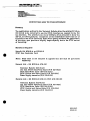
CONVERTING HD20 TO STS06 INTERFACE
Summary
The modifications outlined in this Technical Bulletin allow the existing 20 MByte
IMI 5021H to be converted to use the STS06 Interlace as opposed to the 1M!
bus interface. The procedure will cover 20MByte drives installed in either the
HD-20. or CS-IH products. Completion of this modification allows the use of
Cromemeo's new STOC Controller Board which greatly enhances the performance
of the drive, plus provides a slightly larger capacity due to the STOC method
of formatting.
Materials Required
•
Retrofit Kit HD21K-A or HD21K-B
STOC Disk Contrcller Card
Mote: sroc Card is not included in upgrade kits and must be purchased
separately.
Material List - Kit HD21K-A (CS-1H)
Technical Bulletin (023-9143)
IMI 5021 ST506 Read/Write Board (PIN 410-0450)
STOC Read/Write Cable (PIN 519-0191)
STOC Control and Status Gable (PIN 519-0190)
Power Supply connector (PIN 519-0199)
Material List - Kit HD21K-B (CS-2 & CS-3 with HD-20)
Technical Bulletin (023-9143)
IMI 5021 STS06 Reed/Write Board (PIN 410-0450)
sroc Reed/Write Cable (PIN 519-0195)
STOCControl and Status Gable (PIN 519-0194)
Power Supply connector (PIN 519-0201)
•
023-9143
10.18.84
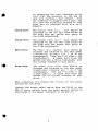
Procedure
1.
Turn off the power to L'1e system, and remove the line cord before
proceeding.
2.
Remove the WDI-II card and the associated data cable from the system
(CS-l,2 OR 3).
3.
Remove the HD20 module from Systems Two or Three by following the
instructions in the HD-20 manual (023-6042).
4.
Remove the hard disk drive from the CS1H by following the front panel
disassembly instructions in the System One manual (023-6022).
5.
For CS-IH systems, replace the power supply cable with the new power
cable provided (519-0199) and proceed to Step 9.
.
6.
To upgrade an HD20 module, remove both the HD20 power supply and the
IMI 5021H drive by following the instructions in the HD20 manual
(023-6042 ).
7.
De-solder and remove the disk drive power cable from the HD20 power
supply board connector J2.
8.
Connect the new disk drive power supply cable (519-0201) by soldering
the purple wire (Cable Pin 1) to Connector J2, Pin 1 on the power supply
board. Connect black wire (Gable Pin 3) to Connector J2, Pin 2 on the
power supply board. Connect the second black wire (Cable Pin 2) to
Connector J2, Pin 4 on the power supply board. Connect the red wire
(Cable Pin 4) to Connector J2, Pin 6 on the power supply board.
.'
•
caution: Use extreme care when performing the following steps. Failure to
follow the recommended procedure exactly could cause damage to
the drive.
9.
Referring to figure 1, separate Read/Write cable from existing WDI-II
Read/Write board using a flat bladed screw driver while board is still
attached to the drive housing. Remove three stand-offs securing the
existing WDI-Il Read/Write board to the drive housing. CarefUlly lift the
WDI-II Read/Write board away from Motor Control board connector and
tilt the board away from the drive housing.
10.
CarefUlly disconnect stepper motor cable from the WDI-II Read/Write
board.
11.
To install the new ST506 Read/Write Board, connect the stepper motor
cable. Guide the Read/Write board into the drive housing, carefully lining
up the Motor Control board connector with the socket on the ST506
Read/Write board. Secure the ST506 Read/Write board with the three stand
offs. CarefUlly reconnect the Read/Write cable with a flat blade screw
driver after the board is attached to the base. This technique is required
to prevent damaging the flat cable or connector contacts.
2
•
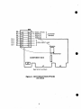
12.
'The STS06 interface card is factory set to respond as drive 0 (DS-1). See
figure 3 for the jwnper settings to cause the drive to respond other than
drive O. Place a jumper in the desired location after removing the existing
jumper located between pins 1 and 16.
13.
Re-install the drive into the CSIH or HD20 cabinet. Route the Read/Write
cable and the Control Status cable as the WDI II data cable had been
routed. See figure 2 for cable connections. Install the STDC Controller
board and connect the Read/Write and control cables. ConneCt this board
last in the priority chain as described in the STDC Manual.
This completes the upgrade of the un 502lE drive to the ST506 configuration.
Perform the checkout procedures for an STDC system as outlined in the STOC
Manual (PIN 023-2031).
3
;:,:-.;t~
(",
I
/
l
I
MOTOR COtfrROL
BOARD CONNECTOR
STEPPER MOTOR
READ/WRITE BOARD
FRAME
Figure 1: READ/WRITE BOARD REMOVAL AND REPLACEMENT
4
CONTROL
AND STATUS
CABLE J1
Pigure 2: INTERPACE CONNECTOR PHYSICAL LOCATIONS
1M} 50218 DRIVE
5
58
57
56
$5
OS-4 _ $4
53
OS-3
OS-2
S2
OS-1
51
-
91011 .....
OS1
-
I\ \... RADIAL OPTION
~8
12 ~
~5
13 ~
14 _
15 _
~4
16-
~
,RES'ERVED
=.7
:=6
:=3
}CUSTOME~
OPTIONS
RESERVED
....
RESERVED
}D~IV~CTl~
'
_2
-1
JUMPERS
D
r--------
OS1 TERMINATOR
COMPONENT SIDE
J J3
1
0
J1
Read/Write Circuit Board
Figure J: DRIVE SELECTION OPTIONS
IMI5021B
6
....
J2