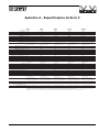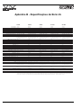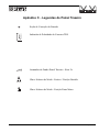
1
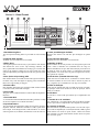
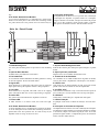
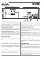
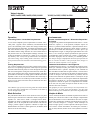
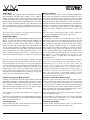
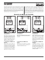
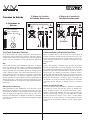
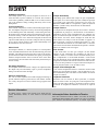
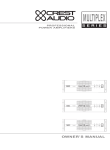
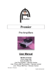
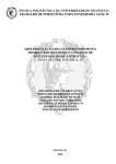
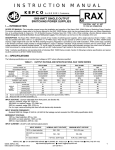
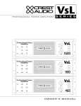
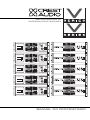
AMPLIFICADORES DE
POTÊNCIA PROFISSIONAL
-6
-3
-10
®
TourClass
-15
Ch A
ACL
Protect
-1
-30
0 dB
-80
Ch A
-42
-30
-18
0dB
-7
Active
-6
-3
-10
-15
Ch B
ACL
Protect
-1
-30
-80
Professional Power Amplifier
0 dB
V1500
Ch B
-6
-3
-10
®
TourClass
-15
Ch A
ACL
Protect
-1
-30
0 dB
-80
Ch A
-42
-30
-18
0dB
-7
Active
-6
-3
-10
-15
Ch B
ACL
Protect
-1
-30
-80
Professional Power Amplifier
0 dB
V1100
Ch B
-6
-3
-10
®
TourClass
-15
Ch A
ACL
Protect
-1
-30
0 dB
-80
Ch A
-42
-30
-18
0dB
-7
Active
-6
-3
-10
-15
Ch B
ACL
Protect
-1
-30
-80
Professional Power Amplifier
0 dB
V900
Ch B
-6
-3
-10
TM
TourClass
-15
Ch A
ACL
Protect
-1
-30
0 dB
-80
Ch A
-42
-30
-18
0dB
-7
Active
-6
-3
-10
-15
Ch B
ACL
Protect
-1
-30
-80
Professional Power Amplifier
0 dB
V650
Ch B
-6
-3
-10
®
TourClass
-15
Ch A
ACL
Protect
-1
-30
0 dB
-80
Ch A
-42
-30
-18
-7
0dB
Active
-6
-3
-10
Ch B
-15
ACL
Protect
-1
-30
Professional Power Amplifier
-80
0 dB
Ch B
V450
MANUAL DO PROPRIETÁRIO
Power Amplifiers
This symbol is used to
alert the operator to follow important operating
procedures and precautions detailed in documentation.
This symbol is used to
warn operators that
uninsulated “dangerous
voltages” are present
within the equipment
enclosure that may pose
a risk of electric shock.
1. Save the carton and packing material even if the
equipment has arrived in
good condition. Should you
ever need to ship the unit, use
only the original factory
packing.
2. Read all the documentation
before operating your
equipment. Retain all documentation for future reference.
Important Precautions
7. Always operate the unit
with the AC ground wire
connected to the eletrical
system ground. Precautions
should be taken so that they
means of equipment is not
defeated.
8. Mains voltage must be correct and the same as that
printed on the rear of the
unit. Damage caused by connection to improper AC voltage is not covered by any
warranty.
9. Have gain controls on
amplifiers turned down
during power-up to prevent
speaker damage if there are
high signal levels at the
inputs.
10. Power down & disconnect
units from mains voltage
before making connections.
3. Follow all instructions
printed on unit chassis for
proper operation.
11. Never hold a power switch
in the “ON” position if it
won’t stay there itself!
4. Do not spill water or other
liquids into or on the unit,
or operate the unit while
standing in liquid.
12. Do not use the unit near
stoves, heat registers, radiators, or other heat producing devices.
5. Make sure power outlets
conform to the power
requirements listed on the
back of the unit.
13. Do not block fan intake or
exhaust ports. Do not operate equipment on a surface or
in an environment which
may impede the normal flow
of air around the unit, such as
a bed, rug, weathersheet, carpet, or completely enclosed
rack. If the unit is used in an
extremely dusty or smoky
environment, the unit should
be periodically “blown free”
of foreign matter.
6. Do not use the unit if the
eletrical power cord is
frayed or broken. The
power supply cords should
be routed so that they are not
likely to be walked or on
pinched by items placed
upon or aganist them, paying
particular attention to cords
and plugs, convenience
receptacles, and the point
where they exit from the
appliance.
14. Do not remove the cover.
Removing the cover will
expose you to potentially
dangerous voltages. There
are no user serviceable parts
inside.
15. Connecting amplifier outputs to oscilliscopes or
other test equipment while
the amplifier is in bridged
mode may damage both the
amplifier and test equipment!
16. Do not drive the inputs
with a signal level greater
than that required to drive
equipment to full output.
17. Do not connect the inputs /
outputs of amplifiers or
consoles to any other voltage source, such as a battery,
mains source, or power supply, regardless of whether the
amplifier or console is turned
on or off.
18. Do not run the output of
any amplifier channel back
into another channel’s
input. Do not parallel- or
series-connect an amplifier
output with any other
amplifier output. Crest
Audio is not responsible for
damage to loudspeakers for
any reason.
19. Do not ground any red
(“hot”) terminal. Never
connect a “hot” (red) output to ground or to another
“hot” (red) output!
20. Non-use periods. The power
cord of equipment should be
unplugged from the outlet
when left unused for a long
period of time.
21. Service Information
Equipment should be serviced by qualified service
personnel when:
A. The power supply cord
or the plug has been damaged;
B. Objects have fallen, or
liquid has been spilled into
the equipment;
C. The equipment has
been exposed to rain;
D. The equipment does
not appear to operate normally, or exhibits a marked
change in performance;
E. The equipment has
been dropped, or the enclosure damaged.
22. To obtain service, contact
your nearest Crest Audio
Service Center, Distributor,
Dealer, or Crest Audio at
201.909.8700 (USA).
Precauções
AMPLIFICADORES DE
Esse Símbolo é usado
para alertar o operador. A
seguir importantes procedimentos operacionais
e precauções detalhadas
na documentação.
Esse símbolo é usado
para advertir o operador
que “voltagens potencialmente perigosas” estão
presentes na parte interna do equipamento e que
podem representar risco
de choque elétrico.
1.
2.
3.
4.
5.
6.
Guarde a caixa e material
de empacotamento mesmo
que o equipamento tenha
chegado
em
boas
condições. Caso algum dia
você precise enviar o
equipamento, use comente
a caixa original de fábrica.
Leia toda a documentação
antes de operar seu
equipamento.
Retenha
toda a documentação para
futuras consultas.
Para operação adequada,
siga todas as instruções
impressas no chassis do
equipamento.
Não respingue água ou
outro líquido dentro ou
sobre o equipamento, ou
opere o equipamento
pisando em líquido.
Certifique-se que a potência das tomadas está em
conformidade com as
exigências de potência listadas na parte traseira do
equipamento.
Não use o equipamento se
a fiação estiver gasta ou
partida. Os cabos de
fornecimento de energia
devem ser instalados de
maneira que não sejam
pisados ou dobrados por
itens colocados sobre ou
contra eles, prestando
atenção especial nos
cabos e tomadas, receptáculos convenientes e o
7.
8.
9.
10.
11.
12.
13.
ponto onde eles saem do
odicamente ser “blown- 21.
aparelho.
free” (soprado) para tirar
partículas estranhas.
Sempre opere o equipamento com o fio terra AC 14. Não remova a tampa.
conectado ao terra do sisRemover a tampa irá expôtema elétrico. Precauções
lo a voltagens potencial- A.
devem ser tomadas com a
mente perigosas. Não exisforma de aterramento para
tem partes internas úteis
que nenhum dos equipaso usuário.
B.
mentos tenham o aterra- 15. Conectar a saída do amplimento anulado.
ficador a osciloscópios ou
A tensão de alimentação
outro equipamento de C.
deve estar correta e ser a
teste enquanto o amplifimesma que a impressa na
cador estiver no modo em D.
parte traseira do equipaponte pode danificar tanto
mento. Danos causados
o amplificador quanto o
pela conexão a uma volequipamento de teste!
tagem AC imprópria, não 16. Não force as entradas com
E.
são cobertos por nenhuma
um nível de sinal maior que
garantia.
o necessário para produzir
a potência máxima do
22.
equipamento.
Mantenha os controles dos
amplificadores na posição 17. Não
conecte
as
de volume mínimo enquanentradas/saídas dos amplito estiver ligando o equipaficadores ou consoles a
mento, para prevenir dano
qualquer fonte de tensão,
ao sonofletor caso existam
independentemente
do
níveis altos de sinais nas
amplificador ou console
entradas.
estar ligado ou desligado.
Desligue e desconecte o 18. Não conecte a saída de
equipamento da tensão de
qualquer canal do amplifialimentação antes de fazer
cador com a entrada de
as conexões.
qualquer outro canal. Não
conecte a saída de um
Nunca segure o interruptor
amplificador com a saída
na posição “ON” caso ele
de qualquer outro, em
não permaneça lá sozinho!
série ou em paralelo. A
Não use o equipamento
Crest Audio, e seus disperto de fornos, raditribuidores não se responadores, ou outros aparesabilizam por dano aos
lhos produtores de calor.
alto-falantes, por qualquer
Não bloqueie a entrada ou
razão.
saída do ventilador. Não
opere o e quipamento em 19. Não aterre nenhum terminal + (“quente”). Nunca
uma superfície ou ambiconecte uma saída +
ente que possa impedir o
(“quente”) ao terra ou a
fluxo normal do ar ao redor
outra saída + (“quente”)!
do equipamento, tais como
20.
Períodos de não utilização:
cama, tapete, carpete ou
o
equipamento deverá ser
rack completamente fechadesligado da tensão de
do. Se o equipamento for
aimentação quando não for
usado em ambiente com
utilizado por um longo
muita poeira ou fumaça, o
período.
equipamento deve peri-
Informações
sobre
Assistência: O equipamento deve ser assistido pelo
pessoal qualificado quando:
Quando o cabo de alimentação ou tomada tenham
sido danificados;
Tivier caído objetos ou derramados líquidos no interior do equipamento;
O equipamento tiver sido
exposto à chuva;
O equipamento parecer
não funcionar ou apresentar uma mudança significativa em seu desempenho;
O equipamento tenha
caído ou tenha seu gabinete danificado.
Para obter assistência,
contate o Centro de
Assistência da Crest Audio
mais
próximo,
o
Distribudor,
o
Representante ou a Crest
Audio
pelo
número
201.909.8700(EUA). No
Brasil
ligue
para
071.358.8313.
Manual do proprietário
do Amplificador de Potência
Table of Contents
Introduction
Unpacking
Installation / Mounting
V Series - Front Panel
Vs Series - Front Panel
V & Vs Series - Back Panel
Operation
Mode Selection
TourClass® Protection Features
Service Information
V Series - Specifications
Vs Series - Specifications
Rear Panel Legend
Índice
1
1
1
2
3
4
5
5
8
9
Appendix A
Appendix B
Appendix C
Introdução
1
Desempacotamento
1
Instalação / Montagem
1
Série V - Painel frontal
2
Série Vs - Painel Frontal
3
Séries V & Vs - Painel Traseiro
4
Funcionamento
5
Seleção do Modo
5
Características da Proteção / TourClass
8
Informações - Assistência Técnica
9
Especificações - Série V
Apêndice A
Especificações - Série Vs
Apêndice B
Legenda do Painel Traseiro
Apêndice C
TourClass ® é marca registrada da Crest Audio Inc.
Introduction
Introdução
Congratulations on your purchase of a Crest Audio power amplifier. Please read this manual carefully as it contains information
vital to the safe operation of your amplifier.
Parabéns... Por sua compra de um amplificador de potência da
Crest Audio. Por favor, leia esse manual cuidadosamente, pois este
contém informações vitais para o funcionamento seguro de seu
amplificador.
Your amplifier represents a major step forward in power amplifier technology and design. It is feature-packed and engineered for
value.
The V and Vs Series incorporate the same design philosophy that
produced Crest’s legendary Professional Series - amplifiers that
have made Crest the standard in touring and installed sound
worldwide. This legacy means that all models include advanced
circuitry capable of providing outstanding reliability and sonic
performance, while TourClass protection circuitry safeguards
your speakers and the amp itself. Built to Crest’s exacting standards from high quality components, V & Vs Series amplifiers are
ideally suited to the most punishing sound reinforcement applications - fixed or mobile.
Unpacking
Upon unpacking, inspect the amplifier. If you find any damage,
notify your dealer immediately. Only the consignee may institute
a claim with the carrier for damage incurred during shipping. Be
sure to save the carton and all packing materials for the carrier’s
inspection. It is a good idea to save the carton and packing material even if the amplifier has arrived in good condition. Should
you ever need to ship the unit back to Crest Audio, one of its
offices, or service centers, use only the original factory packing.
Installation/Mounting.
All V & Vs Series amplifiers are 3-rack space units that can mount
in a standard 19-inch rack. Four front panel mounting holes are
provided. Rear mounting ears give additional support, especially
important in mobile sound systems. Because of the cables and
connectors on the rear panel, a right-angle or offset screwdriver or
hex key will make it easier to fasten the rear mounting ears to the
rails. Optional rack-mount handles are available from your Crest
authorized dealer.
Amplificadores de Potência Crest Audio Séries V & Vs
Seu amplificador representa o mais avançado passo em tecnologia
e design de amplificador de potência. Ele possui características
próprias e arrojado projeto de engenharia.
As Séries V eVs incorporam a mesma filosofia de projeto que produziram a legendária Série Professional da Crest - amplificadores
que têm feito da Crest um padrão em sonorização móvel e fixa,
por todo o mundo. Esse legado significa que todos os modelos
incluem um avançado sistema de circuitos, capazes de oferecer
importante confiabilidade e desempenho sonoro, enquanto o circuito de proteção TourClass protege seus sonofletores e o próprio
amplificador. Fabricado sob os rigorosos padrões de componentes
de alta qualidade, os amplificadores da Série V e Vs são perfeitamente adequados às aplicações sonoras mais severas - tanto fixas
quanto móveis.
Desempacotamento
Após desempacotar, inspecione o amplificador. Se você encontrar
algum dano, notifique seu distribuidor imediatamente. Somente o
consignatário pode reclamar com a transportadora por danos causados durante o transporte. Certifique-se de guardar a caixa e todo
o material de empacotamento para inspeção da transportadora. É
uma boa idéia, guardar a caixa e todo o material de empacotamento mesmo que o amplificador tenha chegado em boas
condições. Caso algum dia você precise enviar o equipamento de
volta para a Crest Audio, para um de seus escritórios ou para a
assistência técnica, use somente o material de empacotamento
original de fábrica.
Instalação/Montagem.
Todos os amplificadores da Série V e Vs possuem unidade de três
espaços de rack que podem ser montados em rack padrão de 19
polegadas. São fornecidos quatro ofícios de montagem no painel
frontal. As abas do painel traseiro dão um suporte adicional, especialmente importantes em sistemas de som móvel. Devido aos
cabos e conectores no painel traseiro, uma chave de 90 ° ou hexagonal facilitará a fixação do painel traseiro nos trilhos, você
encontra alças opcionais para montagem em rack em seu revendedor autorizado da Crest.
Pág.1
Séries V - Painel Frontal
1
2
3
4
6
7
8
9
5
-6
-3
-10
®
TourClass
-15
Ch A
ACL
Protect
-1
-30
-80
5.25"
133mm
0 dB
Ch A
-42
-30
-18
-7
0dB
Active
Ch B
2.25"
57mm
-6
-3
-10
-15
ACL
Protect
-1
-30
-80
Professional Power Amplifier
0 dB
Ch B
V900
19" / 483mm
1. Rack Mounting Ears.
Two front panel mounting holes are provided on each mounting
ear.
1. Abas para Montagem de Rack.
Existem dois orifícios em cada aba para montagem no painel
frontal.
2. Optional Rack Handles.
Available from your authorized Crest Dealer.
2. Alça Opcional Para Rack.
Disponível em seu distribuidor Crest autorizado.
3. Meter Array.
A 20-segment precision meter array is provided for each channel,
and includes the ACL (Active Clip Limiting) indicator. The
array’s peak-hold and instantaneous readings give accurate indication of the channel’s output level. In stereo mode, the arrays
operate independently. In bridged mono mode, they operate in tandem.
3. Medidor de Nível.
Há um medidor de nível de precisão com 20 segmentos para cada
canal e inclui o indicador ACL (Limitador Ativo de Clip). As
leituras instantâneas e de pico dão uma indicação precisa do nível
de saída do canal. No modo estéreo, os indicadores funcionam
independentes. No modo mono em ponte (bridged mono mode),
eles operam em conjunto.
4. ACL (Active Clip Limiting) LED.
Each channel has an ACL LED, located at the right end of the signal meter array. This LED lights at clipping point, and indicates
that Active Clip Limiting is engaged.
4. LED do ACL (Limitador Ativo de Clip).
Cada canal tem um LED do ACL, localizado no extremo direito
do sinal do medidor de nível. Esse LED se acende no ponto de
clip, e significa que o Limitador Ativo de Clip, foi acionado.
5. Protect LEDs.
Each amplifier channel has one red Protect LED. If either channel
is in Protect mode, both LEDs will light.
5. LEDs de Proteção.
Cada canal do amplificador tem um LED de proteção vermelho.
Se qualquer canal estiver também no modo de proteção, ambos
LEDs se acenderão.
6. Active LED.
The green Active LED illuminates to indicate that the amplifier is
turned on.
7. Fan Intake Grill.
A 110 CFM fan mounted behind the fan intake grill draws cooling
air into the amplifier. Do not block this intake!
8. Input Attenuators.
Two front-panel input attenuators adjust level for their respective
amplifier channels. Minimum attenuation (-0dB) equals maximum output. In the bridged mode, both attenuators are used to
control signal level; in addition, both must be set at the same set-
Pág.2
6. LED Ativo.
O LED Ativo verde acende para indicar que o amplificador está
ligado.
7. Tomada de ar do ventilador.
Um ventilador de 110 CFM montado atrás da grelha de entrada,
envia ar para esfriar o amplificador. Não bloqueie essa entrada.!
8. Controles de Volume
Dois atenuadores no painel frontal ajustam o nível de seus respectivos canais de amplificação. A atenuação mínima (-0dB) é igual a
saída máxima. No modo em ponte, ambos volumes são usados
para controlar o nível do sinal; ademais, ambos devem ser ajustados no mesmo ponto.
Amplificadores de Potência Crest Audio Séries V & Vs
ting.
9. AC Power Switch/Circuit Breaker.
V & Vs Series amplifiers have a combination AC switch/circuit
breaker on the front panel. If the switch shuts off during normal
use, push it back to the “ON” position once. If it will not stay on,
9. Interruptor AC/Disjuntor.
Os amplificadores das Séries V & Vs possuem uma combinação
de interruptor AC/ disjuntor, no painel frontal. Se o interruptor
desligar-se durante o uso normal, coloque-o novamente na posição
“ON”. Se ele não permanecer nesta posição sozinho, o amplificador precisa de assistência técnica. Não são usados fusíveis.
Série Vs - Painel Frontal
1
2
3
4
5
6
7
8
5.25"
133mm
2.25"
57mm
19" / 483mm
1. Rack Mounting Ears.
Two front panel mounting holes are provided on each mounting
ear.
1. Suporte Para Montagem de Rack.
Existem dois orifícios para cada suporte para montagem, no painel
frontal.
2. Optional Rack Handles.
Available from your authorized Crest Dealer
2. Alças Opcionais para Racks.
Disponível em seu revendedor autorizado da Crest.
3. Fan Intake Grill.
A 110 CFM fan mounted behind the fan intake grill draws cooling
air into the amplifier. Do not block this intake!
3. Tomada de Ar do Ventilador.
Um ventilador de 110 CFM montado atrás da grelha de entrada,
envia ar para esfriar o amplificador. Não bloqueie essa entrada.!
4. Signal LED.
Each channel has a signal LED. This LED comes on when the
input signal entering the amplifier channel is being amplified.
4. LED de sinal
Cada canal tem um LED indicador de sinal. Esse LED acende
quando existe sinal na entrada do canal do amplificador.
5. Clip LEDs.
Each channel has a clip LED. This LED comes on at clipping
point, and indicates that ACL (Active Clip Limiting) is engaged.
5. Os LEDs “Clip”.
Cada canal tem um LED de “Clip”. Esse LED acende no ponto de
pico e indica que o ACL (Limitador Ativo de Clip) está ligado.
6. Active LED.
The green Active LED indicates the amplifier is turned on.
6. LED Ativo.
O LED Ativo verde indica que o amplificador está ligado.
7. Protect LED.
If either channel is in Protect mode, this LED will light.
7. LED de Proteção
Se qualquer canal estiver no Modo de Proteção, esse LED acenderá.
8. AC Power Switch/Circuit Breaker.
Vs Series amplifiers have a combination AC switch/circuit breaker on the front panel. If the switch shuts off during normal use,
push it back to the “ON” position once. If it will not stay on, the
amplifier needs servicing. No fuses are used.
8. Interruptor de Corrente AC/ Disjuntor.
Os amplificadores da SérieVs tem uma combinação de interruptor
AC/disjuntor no painel frontal. Se o interruptor desligar-se durante
o uso normal, coloque-o novamente na posição “ON”. Se ele não
permanecer ligado sozinho, o amplificador precisa de assistência
técnica. Não são usados fusíveis.
Amplificadores de Potência Crest Audio Séries V & Vs
Pág.3
Séries V & Vs - Painel Traseiro
17.13" / 435mm
5.25"
133mm
9
10
11
12
13
9. 5-Way Binding Post Output Connectors.
For connection with bare wire, banana plug or spade lug output
connections. Connection is made either to the Channel A and
Channel B terminals (Stereo Mode), or across the red (“hot”) terminals only of Channels A and B (Bridge Mode). See the
“Operation” Section for more information.
9. Bornes terminais de saída.
Para conexões com fio descoberto, plug banana ou fio com terminal crimp tipo garfo. A conexão é feita com os terminais Canal A
e Canal B (Modo Estéreo), ou através dos terminais vermelhos
(“quente”) dos Canais A e B (Modo em Ponte). Veja a seção
“Funcionamento”, para maiores informações.
10. Input Attenuators. (Vs Series)
Two input attenuators adjust level for their respective amplifier
channels. In the bridged mode, both attenuators are used to control signal level; in addition, both must be at the same setting.
10. Controles de Volume (Série Vs)
Dois atenuadores de volume de entrada ajustam o nível, para seus
respectivos canais. No Modo em Ponte, ambos atenuadores são
usados para controlar o nível de sinal; ademais, ambos devem estar
ajustados no mesmo ponto.
11. Balanced TRS (1/4") Connectors.
For connection of balanced TRS Input Plugs. See drawing 4 for
information on TRS polarity. Note: Unbalanced "Tip/Sleeve"
plugs may be used with the balanced TRS connectors. The “ring”
terminal or negative input will be connected to ground internally.
12. Mode Selection Switch.
This push-button switch configures the amplifier for either
Stereo or Bridged Mono operation mode. Amplifiers are factoryconfigured for Stereo Mode. See Pages 5-7 for more information.
13. Balanced Barrier Strip Input Connectors.
For connection of bare wire cable or spade lug connectors.
Note: When connecting unbalanced inputs to the Barrier Strip
inputs, make sure to jumper the negative terminal to the ground terminal. Otherwise, a 6 dB drop in signal level will result. See drawings 5 & 6 for Input Barrier Strip diagrams.
14. Fan Exhaust Ports.
Heated air exits the amplifier through the fan exhaust ports,
located on the sides of the amplifier chassis. Be sure not to block
these ports, especially when rack-mounting the amplifier.
Pág.4
11. Conectores TRS (1/4").
Para conexão dos sinais de entrada são fornecidos terminais (1/4")
TRS balanceados. Veja o desenho 4 para informação sobre a polaridade do TRS (1/4"). Nota: Podem ser usados “plugs” mono não
balanceados com os conectores TRS (1/4") balanceados. O terminal “anel” ou entrada negativa será conectado ao terra internamente.
12. Interruptor de Seleção de Modo.
A chave configura o amplificador tanto para o modo Estéreo quanto o Mono em Ponte. Os amplificadores são configurados na fábrica para Modo Estéreo. Veja as páginas 5-7 para maiores informações.
13. Conectores de Entrada “Régua Terminal com
Parafuso” Balanceados.
Para conexões com cabos descobertos ou com terminais crimp tipo
garfo.
Nota: Ao conectar uma entrada não balanceada ao terminal de entrada com parafuso, certifique-se de fazer um jumper do terminal negativo para o terminal terra. De outro modo, se produzirá uma queda de
6 dB no nível de sinal. Ver desenhos 5 e 6 para o diagrama de conexões
com a régua.
14. Aberturas de Saída do Ventilador.
O ar quente sai do amplificador através das aberturas de saída do
ventilador, localizadas nos lados do chassis do amplificador.
Assegure-se de não bloquear essas aberturas, especialmente quando montar o amplificador em um rack.
Amplificadores de Potência Crest Audio Séries V & Vs
Vistas Laterais:
V450, Vs450, V650, Vs650, V900, Vs900
V1100, Vs1100, V1500, Vs1500
2.25"
57mm
1.375"
35mm
2.25"
57mm
1.375"
35mm
12.06" / 306mm
14.56" / 360mm
14
Operation
Funcionamento
Connecting Power / Circuit Size Requirements.
Conexão com Alimentação AC / Dimensões Requeridas
do Circuito
As exigências de potência dos amplificadores das Séries V e Vs são
taxadas em “repouso”, a 1/8 da potência (condições “típicas” de
música) e a potência nominal máxima. A potência máxima da corrente só é limitada pelo disjuntor do painel frontal. Consulte as
especificações no final deste manual para a corrente “típica” que
cada amplificador exigirá. A voltagem principal também deve estar
correta, e ser a mesma que aquela especificada na parte posterior
do amplificador. Danos causados por conectar o amplificador a
uma tensão imprópria, não são cobertos por nenhuma garantia.
Nota: Sempre desligue o amplificador da tensão principal antes de
fazer as conexões de áudio e como precaução extra, desligue os
controles do volume enquanto o estiver ligando.
V & Vs Series amplifier power requirements are rated at “idle”,
1/8th power (“typical” music conditions), and maximum rated
power. The maximum power current draw rating is limited only
by the front panel circuit breaker. Consult the specifications at the
end of this manual for the “typical” current that each amplifier
will demand. Mains voltage must also be correct and the same as
that printed on the rear of the amplifier. Damage caused by connecting the amplifier to improper AC voltage is not covered by
any warranty. Note: Always turn off and disconnect the amplifier
from mains voltage before making audio connections, and as an
extra precaution, have the attenuators turned down during powerup.
Cooling Requirements.
V & Vs Series amplifiers use a forced-air cooling system to maintain a low, even operating temperature. Drawn by a two-speed fan
mounted behind the front panel, air enters through the front grill
and courses through the cooling fins of the heat sink, which dissipates power transistor heat, before exiting through the side panel
ports. Make sure that there is enough space around the front of the
amplifier to allow air to enter, and around the sides of the amp to
allow the heated air to exit. If the amp is rack-mounted, do not use
doors or covers on the front of the rack; the exhaust air must flow
without resistance.
Sistema de Resfriamento e suas Exigências.
Os amplificadores das Séries V e Vs utilizam um sistema de resfriamento por ventilação forçada, para manter uma temperatura de
funcionamento baixa e operante. Aspirado por um ventilador de
duas velocidades montado atrás do painel frontal, o ar entra através
da grelha da frente e circula através das aletas do dissipador térmico, onde se dissipa o calor dos transistores de potência, antes de
sair através das aberturas dos painéis laterais. Certifique-se de que
haja espaço suficiente ao redor da parte dianteira do amplificador
para permitir a entrada do ar, e ao redor dos lados do amplificador
para permitir a saída do ar quente. Se o amplificador for montado
em um rack, não use portas ou tampas na frente do rack, o ar de
saída deve fluir sem resistência.
Note: Whatever type of rack you are using, make sure that the heated
air can escape freely, and that there is no resistance to the intake of
cool air through the front grill.
Nota: Qualquer que seja o tipo do rack que você esteja usando, certifique-se de que o ar quente possa sair livremente e que não exista
nenhum obstáculo para a entrada do ar frio através da grelha frontal.
Mode Selection
Seleção de Modo
The push-button Mode Select switch (located on the rear panel
between input connections for Channels A and B) configures the
amplifier for either Stereo Mode or Bridged Mono Mode.
Amplifiers are factory-configured for Stereo Mode. To bridge the
amplifier, turn it off, and push the mode selection switch to the
“bridge” position. Signal is applied to Channel A’s input only.
Both attenuators are used to control signal level; in addition, both
must be set at the same setting.
A chave de Seleção de Modo (localizada no painel traseiro entre as
entradas para conexão dos Canais A e B) configura o amplificador
tanto no Modo Estéreo como no Modo Mono em Ponte. Os amplificadores são configurados na fábrica para Modo Estéreo. Para utilizá-lo em Ponte, desligue-o e coloque o botão interruptor na
posição “bridge” (ponte). O sinal é aplicado somente para a entrada do Canal A. Ambos atenuadores são usados para controlar o
nível do sinal; ademais, ambos devem estar ajustados ao mesmo
ponto.
Amplificadores de Potência Crest Audio Séries V & Vs
Pág.5
Stereo Mode.
In Stereo Mode, both channels operate independently, with their
input attenuators controlling their respective levels. Signal at
Channel A’s input produces output at Channel A’s output, while
signal at Channel B’s input produces output at Channel B’s output.
Recommended minimum nominal load impedance for stereo operation is 2 ohms per channel. Either the 1/4" (TRS) inputs or the
barrier strip inputs may be used. Loudspeakers are connected to
the red and black 5-way output binding posts (Drawing 1) for each
channel.
Modo em Estéreo.
No Modo em Estéreo, ambos canais funcionam independentemente, com seus atenuadores de entrada controlando seus respectivos níveis. Um sinal na entrada do Canal A produz um sinal
amplificado na saída do Canal A, enquanto um sinal na entrada do
Canal B produz um sinal amplificado na saída do Canal B. A
impedância nominal mínima recomendada para o funcionamento
do Estéreo é de 2 ohms por canal. Podem ser usadas , também, as
entradas 1/4" (TRS) ou as réguas terminais. Os alto-falantes são
ligados aos bornes vermelhos e pretos (Desenho 1) para cada
canal.
Note: Do not connect speakers to the Bridged output when using Nota: Não conecte os alto-falantes às saídas em Ponte, quando estithe amplifier in Stereo Mode. (Drawing 1).
ver usando o amplificador em Modo Estéreo. (Desenho 1).
Bridged Mono Mode.
Bridged Mono Mode straps both amplifier channels together to
make a very powerful single channel monaural amplifier. One
channel “pushes” and the other “pulls” equally, doubling the
power over that of either channel alone. Signal is applied to
Channel A’s input only. In the bridged mode, both attenuators are
used to control signal level; in addition, both must be set at the
same setting. Either the 1/4" (TRS) input or the barrier strip input
may be used. Speakers are connected across the red “hot” (+) terminals: connect A’s terminal to the positive (+) speaker wire, and
connect B’s terminal to the negative (-) speaker wire. (Drawing 2).
Modo Mono em Ponte.
O Modo Mono em Ponte une conjuntamente ambos canais do
amplificador, para fazer um amplificador monoaural de canal
único, muito potente. Os dois canais trabalham em oposição de
fases (“push-pull”), dobrando a potência de cada canal. O sinal é
aplicado somente à entrada do Canal A. No Modo em Ponte,
ambos controles de volume são usados para controlar o nível do
sinal; ademais, ambos devem estar ajustados ao mesmo ponto.
Tanto a entrada 1/4(TRS) quanto a régua terminal, podem ser usados. Os alto-falantes são conectados através dos terminais vermelhos “quentes” (+): conecte o terminal A ao cabo positivo (+) do
alto-falante e conecte o terminal B ao cabo negativo do altofalante (Desenho 2).
Note: Use extreme caution when operating the amplifier in bridged
mode. Never ground either side of the speaker cable when the amplifier is in bridged mode; both sides are “hot.” If an output patch panel
is used, all connections must be isolated from each other and from the
panel. The recommended minimum nominal load impedance in the
bridged mode is 4 ohms, which is the equivalent to driving both channels at 2 ohms. Driving bridged loads of less than the recommended
minimums will activate the IGM circuitry, resulting in a loss of power,
and may also cause a thermal protect condition.
Nota: Tenha extremo cuidado ao usar o amplificador no Modo em
Ponte, nunca aterre nenhum dos cabos do alto-falante quando o
amplificador estiver no modo em ponte; ambos lados são
“quentes”. Se for utilizado um painel de comutação, todas as
conexões devem ser isoladas entre si e em relação ao painel. A
impedância nominal mínima recomendada no modo em ponte é
de 4 ohms, o que equivale a usar ambos canais a 2 ohms. Usar em
Ponte, uma carga inferior à recomendada, ativará os circuitos
IGM, resultando em perda de potência e também poderá provocar
uma situação de proteção térmica.
Sending One Signal to Both Channels.
(Drawing 3) To send the same signal to both channels, connect the
input signal to Channel A via the TRS input connector or the Input
Barrier Strip. Run jumpers from the positive and negative connectors of Channel A’s Input Barrier Strip to those of Channel B’s.
Both channels share the input signal, but will operate independently. Speakers are connected as in Stereo Mode.
Envio de um Sinal Para Ambos Canais.
(Desenho 3) Para enviar um mesmo sinal para ambos canais,
conecte o sinal de entrada ao Canal A pelo conector de Entrada
1/4" (TRS) ou à régua terminal de entrada. Leve os jumpers dos
conectores positivos e negativos da régua terminal de entrada do
Canal A para aqueles do Canal B. Ambos canais compartilham o
sinal de entrada, mas funcionarão independentemente. Os altofalantes são conectados como no Modo Estéreo.
Note: Regardless of operating mode, NEVER connect amplifier outputs together!
Nota : Independentemente do modo de operação, NUNCA conecte as
saídas do amplificador juntas.
Speakers are connected using 5-way Output Binding Post connectors. For more information, see the sections on Stereo & Bridged
Mono mode and Drawings 1-3.
Os alto-falantes são conectados usando os Conectores Terminais
de Caixa. Para maiores informações, veja as seções de Modo
Estéreo e Mono em Ponte. Desenhos 1-3.
Connecting Inputs.
Both the barrier strip and 1/4-inch TRS input connectors accept
balanced and unbalanced audio connections.
Conexões de Entradas.
Tanto as Réguas Terminais quanto os jacks 1/4" TRS aceitam
conexões de áudio balanceadas e não balanceadas.
Pag. 6
Amplificadores de Potência Crest Audio Séries V & Vs
Note: When using three-pole (‘stereo’) TRS connectors to connect
unbalanced signals, make sure that the ring (negative) connection is
made either to the cold (-) output of the source equipment, or to
ground. Unbalanced, two-pole connectors may be used without modification. In Stereo Mode, one or both channels may be used. In the
Bridged Mono Mode, both outputs are driven from Channel A’s input;
Channel B’s input is unused. (See drawings 1-6).
Nota: Quando estiver usando os conectores tripolares (“estéreo”)
TRS para conectar sinais não balanceados, assegure-se que a
conexão de anel (negativa) seja feita também à saída fria (-) do
equipamento de origem ou à terra. Conectores bipolares não balanceados podem ser usados sem modificação. No Modo Estéreo, um
ou ambos canais podem ser usados. No Modo Mono em Ponte ambas
saídas são levadas da entrada do Canal A ; a entrada do Canal B não
é usada. (Veja os desenhos 1-6).
Desenho de Modo de Conexão
Bridge
Bridge
Output
Ch.B
Ch.A
+ +Output
Bridge
Crest Audio Inc.
100 Eisenhower Dr.
Paramus New Jersey, 07652 USA
Crest Audio Inc.
100 Eisenhower Dr.
Paramus New Jersey, 07652 USA
Crest Audio Inc.
100 Eisenhower Dr.
Paramus New Jersey, 07652 USA
A
B
A
+
+
A
B
+
B
+
A
+
B
+
A+B
A+B
+
Designed & manufactured in the USA by:
+
Designed & manufactured in the USA by:
+
Designed & manufactured in the USA by:
B
Ch.A
CLASS 2 WIRING MAY BE USED
CLASS 2 WIRING MAY BE USED
CLASS 2 WIRING MAY BE USED
+ --
+
+ +Output
+
Output
Ch.B
Ch.A
-- +
+
--
+ +Output
+
Output
Ch.B
--
+
+
A
+
A
B
+
--
+
A+B
1. Stereo Mode
Connections
2. Bridged Mode
Connections
3. Parallel Mode
Connections
Either TRS or Input Barrier Strips
(but not both) may be used for input
connections to Channels A & B. In
this diagram, bare wire has been connected to the Input Barrier Strip of
Channel A, while a TRS plug is
being connected to Channel B.
Either TRS or Input Barrier Strips (but not
both) may be used for input connection to
Channel A.
Input is connected to Channel A using
either a TRS connector or the Input
Barrier Strip (but not both). Jumper
from Channel A to Channel B for
ground is not necessary; however,
input ground connection to Channel A
must be made.
1. Conexões no Modo em
Estéreo
2. Conexões no Modo em
Ponte
3. Conexões no Modo em
Paralelo
Tanto os TRS quanto Réguas de
Terminais (mas não ambos), podem
ser usados para conexões de entrada
do Canal A e B. Nesse diagrama, o
fio descoberto foi conectado a Régua
de Terminais do Canal A, enquanto o
plug TRS foi conectado ao Canal B.
Tanto o TRS como as Réguas de Terminais
(mas não ambos) podem ser usados para a
conexão de entrada do Canal A.
A Entrada é conectada ao Canal A
usando, tanto um conector ou régua
de terminais (Mas não ambos.) Não é
necessário fazer um jumper do Canal A para o canal B; Contudo a
conexão de entrada terra para o canal A deve ser feita.
Amplificadores de Potência Crest Audio Séries V & Vs
Pag. 7
B
Tip - Positive (+)
B
+
A
Ring - Negative (-)
+
4. Polaridade de
Entrada
6. Régua de Conexão de
Entrada Desbalanceada
+
5. Régua de Conexão
de Entrada Balanceada
Conexões de Entrada
+
B
A
B
A+B
A+B
+
Sleeve - Ground ( )
Jumper
+
-
+
-
TourClass Protection Features
Características da Proteção TourClass
Every model in the V & Vs Series incorporates TourClass protection features. Derived from Crest’s extensive experience with the
world’s largest sound rental companies, the TourClass group of
circuits sets new standards in load and amplifier protection.
Todos os modelos da Serie V & Vs incorporan características de
proteção TourClass. Oriunda da larga experiência da Crest, com
as maiores empresas de aluguel de som do mundo, o grupo de circuitos TourClass estabelce novos padrões na proteção de carga
do amplificador.
ACL.
(Active Clip Limiting). At the amplifier’s full power, or clipping
point, ACL will be activated. This is is indicated by illumination
of the Clip/ACL LED. The channel gain will automatically be
reduced, guarding the loudspeakers against the damaging high
power, continuous square waves that would otherwise be produced. Situations that may activate ACL include: uncontrolled
feedback, oscillations, or an improper equipment setting or malfunction upstream from the amplifier. Normal program transients
will not trigger ACL; only steady or excessive clipping will. ACL
is virtually transparent in operation and full signal bandwidth is
maintained.
ACL.
(Active Clip Limiting / Limitação Ativa de Clip). Na potência
máxima do amplificador ou ponto de clipping, o ACL é ativado.
Isso é indicado pela iluminação do LED do Clip / ACL.O circuito
limitador de Clip reduzirá automaticamente o ganho do volume a
um nível que evite o clipping, preservando o sonofletor contra as
danosas onda quadradas de alta potência que podem ser produzidas. Situações que podem ativar o limitador de Clip incluem realimentação descontrolada, oscilações, ajuste inadequado do
equipamento. As oscilações normais do programa não acionarão
o limitador de Clip. Somente o clipping excessivo e estável o
fará.
IGM Impedance Sensing.
IGM (Instantaneous Gain Modulation) is an innovative circuit
that allows the amplifier to operate safely into loads as low as 2
ohms. When the amplifier sees a load that overstresses the output
stage, the IGM circuit adjusts the channel gain to a safe level.
Like ACL, the IGM circuit is inaudible in normal use. In addition,
if extreme low impedance is encountered, the amplifier’s output
relay will open.
Sensor de Impedância IGM
IGM (Instantaneous Gain Modulation / Modulação Instantânea
de Ganho) um circuito inovador que permite ao amplificador,
operar , de maneira segura, com cargas tão baixas quanto 2 ohms.
Quando o amplificador identifica que uma carga representa um
extremo esforço na etapa de saída, o circuito IGM ajusta o ganho
do canal, para um nível seguro. Como o ACL, o circuito IGM é
inaudível em uso normal. Ademais, se uma impedância extremamente baixa for encontrada, será aberto o relé de saída do amplificador.
Pag. 8
Amplificadores de Potência Crest Audio Séries V & Vs
AutoRamp Protection.
Auto Ramp operates every time the amplifier is turned on or is
reactivated after a protect condition is corrected. This exclusive
Crest feature gradually (-80dB to 0dB in 3.0 seconds) increases
gain to the attenuator setting avoiding unnecessary stress on the
loudspeakers.
Thermal Protection.
If the heatsink temperature reaches an abnormally high temperature, the amplifier will protect itself by disconnecting loudspeakers and shutting down until sufficiently cooled. During this time,
the Protect LED’s will light. If the power transformer gets too hot,
its thermal sensing circuit will disconnect both channel outputs.
During this time, the Active LED will extinguish, the Protect and
Clip/ACL LEDs will stay lit, and the cooling fan will stay running
at low speed. Normal operation will resume automatically once
the transformer cools to a safe level
Short Circuit.
If an output is shorted (i.e., defective speakers or crossed speaker
wires) the IGM and thermal circuits will automatically protect the
amplifier. The IGM circuit senses the short circuit as an extremely stressful load condition and attenuates the signal, protecting the
channel’s output transistors from overcurrent stress. If the short
circuit remains, the load will be disconnected by the thermal protection circuitry.
DC Voltage Protection.
If an amplifier channel detects DC voltage at its output terminals,
the output relay will immediately open to prevent loudspeaker
damage. The Protect LEDs will light.
Subsonic Frequencies.
The V & Vs Series amplifiers have built-in high pass filtering to
provide subsonic frequency protection for each channel. In addition, a relay will open if excessive subsonic energy appears at the
output.
Proteção Auto-Ramp
O Auto-Ramp opera durante todo o tempo em que o amplificador
estiver ligado, ou se reativa depois que uma condição de proteção
seja corrigida. Essa característica exclusiva da Crest eleva gradualmente (-80dB à 0dB em 3.0 segundos) o ganho do ajuste do
atenuador, evitando esforço desnecessário dos alto-falantes.
Proteção Térmica.
Se a temperatura do dissipador alcançar um nível alto e anormal,
o amplificador irá proteger-se, desconectando os alto-falantes e
desligando-se até que esteja suficientemente frio. Durante esse
tempo, os LEDs de Proteção acenderão. Se o transformador ficar
quente demais, seu sensor térmico desligará as saídas dos dois
canais. Durante esse tempo o LED de atividade se apagará e os
LEDs de Proteção e Clip ACL permanecerão ligados e o ventilador continuará funcionando em velocidade baixa. O funcionamento normal será retomado automaticamente quando o transformador tiver resfriado a um nível seguro.
Curto Circuito.
Se uma saída entrar em curto (por exemplo: um alto falante
defeituoso ou um cruzamento dos condutores do cabo do alto-falante) o IGM e os circuitos térmicos automaticamente protegerão o amplificador. O circuito IGM identifica o curto-circuito
como uma situação de carga extremamente baixa e atenua o sinal
protegendo os transistores de saída do canal de uma sobrecorrente.
Se o curto-circuito permanecer a carga será desconectada pelo circuito de proteção térmica (o relé de saída se abre).
Proteção Contra Voltagem DC.
Se um canal de amplificador detecta a existência de uma tensão
contínua, em seus terminais de saída, o relé de saída abre os contatos imediatamente para evitar danos aos alto-falantes. O LED de
proteção se acenderá.
Freqüência Subsônica
Fabricados com um sistema de filtros passa-alta, os amplificadores de Séries V&Vs são protegidos contra freqüências subsônicas, em cada canal. Ademais, o relé abrirá se aparecer energia
proveniente de freqüências subsônicas excessivas na etapa de
saída.
Service Information
To obtain service, contact your nearest Crest Audio Service
Center, Distributor, Dealer, or Crest Audio at 201.909.8700
(USA).
Amplificadores de Potência Crest Audio Séries V & Vs
Informação Sobre Assistência Técnica.
Para obter assistência técnica, contate seu Centro de Serviço,
Distribuidor, Representante mais próximo ou com a Crest Audio,
pelo número 201.909.8700 (EUA), no Brasil ligue para
Page 9
Apêndice A - Especificações da Série V
V450
V650
V900
V1100
V1500
8Ω Stereo Power † 150 Watts
200 Watts
250 Watts
300 Watts
400 Watts
4Ω Stereo Power † 225 Watts
325 Watts
450 Watts
550 Watts
750 Watts
2Ω Stereo Power † 325 Watts
425 Watts
550 Watts
700 Watts
1000 Watts
8Ω Bridged Power † 450 Watts
650 Watts
900 Watts
1100 Watts
1500 Watts
4Ω Bridged Power † 650 Watts
850 Watts
1100 Watts
1400 Watts
2000 Watts
44.5V
52.3V
55.9V
70.7V
63V
74V
79V
100V
10Hz-20kHz, -3dB @ 165kHz
10Hz-20kHz, -3dB @ 165kHz
10Hz-20kHz, -3dB @ 165kHz
10Hz-20kHz, -3dB @ 165kHz
20Hz-20kHz
20Hz-20kHz
20Hz-20kHz
20Hz-20kHz
ACL, IGM, AutoRamp, short circuit,
ACL, IGM, AutoRamp, short circuit,
ACL, IGM, AutoRamp, short circuit,
ACL, IGM, AutoRamp, short circuit,
DC voltage, turn-on/off transient, current
DC voltage, turn-on/off transient, current
DC voltage, turn-on/off transient, current
DC voltage, turn-on/off transient, current
DC voltage, turn-on/off transient, current
inrush, sub/ultrasonic input.
inrush, sub/ultrasonic input.
inrush, sub/ultrasonic input.
inrush, sub/ultrasonic input.
inrush, sub/ultrasonic input.
<1.0%
<1.0%
<1.0%
<1.0%
<0.05%
<0.05%
<0.05%
<0.05%
>800:1
>1000:1
>1000:1
>1000:1
> - 64dB
> - 64dB
> - 64dB
> - 64dB
.775V
1.0 V
1.0V
1.4V
X46
X40
X46
X38.6
>20kΩ/>10kΩ
>20kΩ/>10kΩ
>20kΩ/>10kΩ
>20kΩ/>10kΩ
-105 dB
-105 dB
-105 dB
-105 dB
> - 60 dB
> - 60 dB
> - 60 dB
> - 60 dB
AB
AB
AB
H
TRS (tip +) & Barrier Strip
TRS (tip +) & Barrier Strip
TRS (tip +) & Barrier Strip
TRS (tip +) & Barrier Strip
5-way binding posts or Speakon
5-way binding posts or Speakon
5-way binding posts or Speakon
5-way binding posts or Speakon
(market dependent)
(market dependent)
(market dependent)
(market dependent)
36,000 µF
38,000 µF
36,000 µF
50,000 µF
100V-240V, 50-60Hz
100V-240V, 50-60Hz
100V-240V, 50-60Hz
100V-240V, 50-60Hz
Idle Current Draw (120V) 1.0A
1.6A
2.8A
2.0A
1.8A
1/8 Power Curr. Draw (typical music, 120V/4Ω) 3.5A
6.4A
7.2A
8.6A
4.3A
1/3 Power Curr. Draw (continuous music, 120V/4Ω) 5.2A
7.8A
10.4A
12.4A
8.5A
12.0A
15.0A
18.0A
21.0A
Thermal Emissions (1/8 Power, 4Ω) 1300 BTU/hr
1460 BTU/hr
2000 BTU/hr
2400 BTU/hr
3100 BTU/hr
Thermal Emissions (1/3 Power, 4Ω) 1530 BTU/hr
2100 BTU/hr
2900 BTU/hr
3400 BTU/hr
4400 BTU/hr
Front to Side, one 110 CFM, 2-Speed fan
Front to Side,one 110 CFM, 2-Speed fan
Front to Side, one 110 CFM, 2-Speed fan
Front to Side, one 110 CFM, 2-Speed fan
Max RMS Output Voltage (each channel) 36V
Peak Output Voltage (each channel) 51V
Frequency Response (+0/-0.3dB, 1W/8Ω) 10Hz-20kHz, -3dB @ 165kHz
Power Bandwidth (Rated power at 4Ω, 1% THD+N) 20Hz-20kHz
TourClass Protection ACL, IGM, AutoRamp, short circuit,
THD+N (rated power at 4Ω, 1kHz) <1.0%
SMPTE IMD (rated power at 8Ω, 60Hz & 7kHz) <0.05%
Damping Factor (10-400Hz at 8Ω) >700:1
Input CMRR (1 kHz) > - 64dB
Input Sensitivity (rated power at 8Ω) .775V
Voltage Gain X38.6
Input Impedance (balanced/unbalanced) >20kΩ/>10kΩ
Hum & Noise (“A” weighted, full power at 4Ω) -105 dB
Crosstalk (“A” weighted, full power at 4Ω) > - 60 dB
Class AB
Input Connectors (per channel) TRS (tip +) & Barrier Strip
Output Connectors (per channel) 5-way binding posts or Speakon
(market dependent)
Filter Storage 44,000 µF
Power Supply (factory configured) 100V-240V, 50-60Hz
Max Curr. Draw (circuit breaker rating, 120V/4Ω) 8.0A
Cooling Front to Side, one 110 CFM, 2-Speed fan
Controls Front Panel: 2 attenuators, magnetic circuit Front Panel: 2 attenuators, magnetic circuit Front Panel: 2 attenuators, magnetic circuit Front Panel: 2 attenuators, magnetic circuit Front Panel: 2 attenuators, magnetic circuit
breaker/power switch.
breaker/power switch.
breaker/power switch.
breaker/power switch.
breaker/power switch.
Rear Panel: mode select switch.
Rear Panel: mode select switch.
Rear Panel: mode select switch.
Rear Panel: mode select switch.
Rear Panel: mode select switch.
20-segment signal meter w/peak hold,
20-segment signal meter w/peak hold,
20-segment signal meter w/peak hold,
20-segment signal meter w/peak hold,
Protect, Active, Active Clip Limiting
Protect, Active, Active Clip Limiting
Protect, Active, Active Clip Limiting
Protect, Active, Active Clip Limiting
14 gauge steel
14 gauge steel
14 gauge steel
14 gauge steel
5.25" x 19" x 12" / 133 x 483 x 305mm
5.25" x 19" x 12" / 133 x 483 x 305mm
5.25" x 19" x 13.33" / 133 x 483 x 339mm 5.25" x 19" x 13.33" / 133 x 483 x 339mm
38 lbs. / 17.3 kg., 36 lbs. / 16.3 kg.
46 lbs. / 20.9 kg., 44 lbs. / 20.0 kg.
47 lbs. / 21.3 kg., 44 lbs. / 20.0 kg.
49 lbs. / 22.2 kg., 46 lbs / 20.9 kg.
3 years*
3 years*
3 years*
3 years*
LED Indicators (per channel) 20-segment signal meter w/peak hold,
Protect, Active, Active Clip Limiting
Construction 14 gauge steel
Dimensions 5.25" x 19" x 12" / 133 x 483 x 305mm
(Height x Width x Depth to rear rack ears)
Gross Weight, Net Weight 38 lbs. / 17.3 kg., 36 lbs. / 16.3 kg.
Warranty 3 years*
† Power figures are watts per channel, both channels driven, 1kHz, 1% THD . ◊ Approximate Values § Limited by Circuit Breaker ‡ Active Clip Limiting
* Garantia de 3 (três) anos no Brasil. Os Amplificadores da linha V e Vs vêm com garantia padrão de 2 (dois) anos, mais 1 (um) ano adicional se o cartão de registro for enviado para a Foxtrot Comércio Importação e
Exportação Ltda. Tel. 071.358.8313. Crest Audio reserves the right to make improvements in manufacturing or design which may affect specifications. ©1997 Crest Audio Inc. 10/13/97
Amplificadores de Potência Crest Audio Séries V & Vs
Apêndice A
Apêndice B - Especificações da Série Vs
Vs650
Vs900
Vs1100
Vs1500
8Ω Stereo Power † 150 Watts
Vs450
200 Watts
250 Watts
300 Watts
400 Watts
4Ω Stereo Power † 225 Watts
325 Watts
450 Watts
550 Watts
750 Watts
2Ω Stereo Power † 325 Watts
425 Watts
550 Watts
700 Watts
1000 Watts
8Ω Bridged Power † 450 Watts
650 Watts
900 Watts
1100 Watts
1500 Watts
4Ω Bridged Power † 650 Watts
850 Watts
1100 Watts
1400 Watts
2000 Watts
44.5V
52.3V
55.9V
70.7V
63V
74V
79V
100V
10Hz-20kHz, -3dB @ 165kHz
10Hz-20kHz, -3dB @ 165kHz
10Hz-20kHz, -3dB @ 165kHz
10Hz-20kHz, -3dB @ 165kHz
20Hz-20kHz
20Hz-20kHz
20Hz-20kHz
20Hz-20kHz
ACL, IGM, AutoRamp, short circuit,
ACL, IGM, AutoRamp, short circuit,
ACL, IGM, AutoRamp, short circuit,
ACL, IGM, AutoRamp, short circuit,
DC voltage, turn-on/off transient, current
DC voltage, turn-on/off transient, current
DC voltage, turn-on/off transient, current
DC voltage, turn-on/off transient, current
DC voltage, turn-on/off transient, current
inrush, sub/ultrasonic input.
inrush, sub/ultrasonic input.
inrush, sub/ultrasonic input.
inrush, sub/ultrasonic input.
inrush, sub/ultrasonic input.
THD+N (rated power at 4Ω, 1kHz) <1.0%
<1.0%
<1.0%
<1.0%
<1.0%
SMPTE IMD (rated power at 8Ω, 60Hz & 7kHz) <0.1%
<0.1%
<0.1%
<0.1%
<0.1%
Damping Factor (10-400Hz at 8Ω) >700:1
>800:1
>1000:1
>1000:1
>1000:1
> - 64dB
> - 64dB
> - 64dB
> - 64dB
.775V
1.0 V
1.0V
1.4V
X46
X40
X46
X38.6
>20kΩ/>10kΩ
>20kΩ/>10kΩ
>20kΩ/>10kΩ
>20kΩ/>10kΩ
-105 dB
-105 dB
-105 dB
-105 dB
> - 60 dB
> - 60 dB
> - 60 dB
> - 60 dB
AB
AB
AB
H
TRS (tip +) & Barrier Strip
TRS (tip +) & Barrier Strip
TRS (tip +) & Barrier Strip
TRS (tip +) & Barrier Strip
5-way binding posts or Speakon
5-way binding posts or Speakon
5-way binding posts or Speakon
5-way binding posts or Speakon
(market dependent)
(market dependent)
(market dependent)
(market dependent)
36,000 µF
38,000 µF
36,000 µF
50,000 µF
100V-240V, 50-60Hz
100V-240V, 50-60Hz
100V-240V, 50-60Hz
100V-240V, 50-60Hz
Idle Current Draw (120V) 1.0A
1.6A
2.8A
2.0A
1.8A
1/8 Power Curr. Draw (typical music, 120V/4Ω) 3.5A
6.4A
7.2A
8.6A
4.3A
1/3 Power Curr. Draw (continuous music, 120V/4Ω) 5.2A
7.8A
10.4A
12.4A
8.5A
12.0A
15.0A
18.0A
21.0A
Thermal Emissions (1/8 Power, 4Ω) 1300 BTU/hr
1460 BTU/hr
2000 BTU/hr
2400 BTU/hr
3100 BTU/hr
Thermal Emissions (1/3 Power, 4Ω) 1530 BTU/hr
2100 BTU/hr
2900 BTU/hr
2900 BTU/hr
4400 BTU/hr
Front to Side, one 110 CFM, 2-Speed fan
Front to Side, one 110 CFM, 2-Speed fan
Front to Side, one 110 CFM, 2-Speed fan
Front to Side, one 110 CFM, 2-Speed fan
Front panel: magnetic circuit
Front panel: magnetic circuit
Front panel: magnetic circuit
Front Panel: magnetic circuit
Max RMS Output Voltage (each channel) 36V
Peak Output Voltage (each channel) 51V
Frequency Response (+0/-0.3dB, 1W/8Ω) 10Hz-20kHz, -3dB @ 165kHz
Power Bandwidth (Rated power at 4Ω, 1% THD+N) 20Hz-20kHz
TourClass Protection ACL, IGM, AutoRamp, short circuit,
Input CMRR (1 kHz) > - 64dB
Input Sensitivity (rated power at 8Ω) .775V
Voltage Gain X38.6
Input Impedance (balanced/unbalanced) >20kΩ/>10kΩ
Hum & Noise (“A” weighted, full power at 4Ω) -105 dB
Crosstalk (“A” weighted, full power at 4Ω) > - 60 dB
Class AB
Input Connectors (per channel) TRS (tip +) & Barrier Strip
Output Connectors (per channel) 5-way binding posts or Speakon
(market dependent)
Filter Storage 44,000 µF
Power Supply (factory configured) 100V-240V, 50-60Hz
Max Curr. Draw (circuit breaker rating, 120V/4Ω) 8.0A
Cooling Front to Side, one 110 CFM, 2-Speed fan
Controls Front panel: magnetic circuit
breaker/power switch. Rear Panel: 2 atten- breaker/power switch. Rear Panel: 2 atten- breaker/power switch. Rear Panel: 2 atten- breaker/power switch. Rear Panel: 2 atten- breaker/power switch. Rear Panel: 2 attenuators, mode select switch.
LED Indicators (per channel) 1 Clip, 1 Signal per channel, Protect,
Active
Construction 14 gauge steel
Dimensions 5.25" x 19" x 12" / 133 x 483 x 305mm
uators, mode select switch.
uators, mode select switch.
uators, mode select switch.
uators, mode select switch.
1 Clip, 1 Signal per channel, Protect,
1 Clip, 1 Signal per channel, Protect,
1 Clip, 1 Signal per channel, Protect,
1 Clip, 1 Signal per channel, Protect,
Active
Active
Active
Active
14 gauge steel
14 gauge steel
14 gauge steel
14 gauge steel
5.25" x 19" x 12" / 133 x 483 x 305mm
5.25" x 19" x 12" / 133 x 483 x 305mm
5.25" x 19" x 13.33" / 133 x 483 x 339mm 5.25" x 19" x 13.33" / 133 x 483 x 339mm
41 lbs. / 18.6 kg., 39 lbs. / 17.7 kg.
46 lbs. / 20.9 kg., 44 lbs. / 20.0 kg.
46 lbs. / 20.9 kg., 43 lbs. / 19.5 kg.
49 lbs. / 22.2 kg., 46 lbs / 20.9 kg.
3 years*
3 years*
3 years*
3 years*
(Height x Width x Depth to rear rack ears)
Gross Weight, Net Weight 38 lbs. / 17.3 kg., 36 lbs. / 16.3 kg.
Warranty 3 years*
* Garantia de 3 (três) anos no Brasil. Os Amplificadores da linha V e Vs vêm com garantia padrão de 2 (dois) anos, mais 1 (um) ano adicional se o cartão de registro for enviado para a Foxtrot Comércio Importação e
Exportação Ltda. Tel. 071.358.8313. Crest Audio reserves the right to make improvements in manufacturing or design which may affect specifications. ©1997 Crest Audio Inc. 10/13/97
Apêndice B
Amplificadores de Potência Crest Audio Séries V & Vs
Apêndice C - Legendas do Painel Traseiro
+
Seção de Conecção de Entrada
Indicador de Polaridade do Conector TRS
A
B
A+B
Atenuador de Ganho Painel Traseiro - Série Vs
Chave Seletora de Modo - Estéreo / Posição Paralelo
Chave Seletora de Modo - Posição Ponte Mono
A+B
Amplificadores de Potência Crest Audio Séries V & Vs
Apêndice C
Crest Audio Inc.
100 Eisenhower Dr., Paramus NJ 07652 USA
TEL: 201.909.8700 FAX: 201.909.8744
http://www.crestaudio.com
Printed in USA
v. 1.1
10/24/97 © 1997 Crest Audio, Inc.
A escolha dos profissionais.
C4400011