1
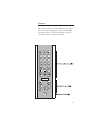
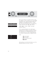
Ayre KX-5
Owner’s Manual
Variable-Gain Line Stage Preamplifier
Table of
Contents
Welcome to
Ayre . . . . . . . . . . . . . . . . . . . . . . . 2
Connections and
Installation . . . . . . . . . . . . . . . . . . . . 3
Setup and
Configuration . . . . . . . . . . . . . . . . . . . 7
Controls and
Operation . . . . . . . . . . . . . . . . . . . . 10
Optimization and
Customization . . . . . . . . . . . . . . . . . . 17
Numbers and
Specifications . . . . . . . . . . . . . . . . . . 28
In Case of
Trouble . . . . . . . . . . . . . . . . . . . . . 29
Statement of
Warranty . . . . . . . . . . . . . . . . . . . . 32
A Place for
Notes . . . . . . . . . . . . . . . . . . . . . . 35
Welcome to
Ayre
To our North American
customers, please be sure to
mail your warranty
registration card and
photocopy of your original
sales receipt within 30 days
in order to extend the
warranty to five years.
Your Ayre KX-5 offers a significant advance in the
musical performance of high-fidelity equipment.
The warmth and immediacy of a live performance
are apparent from the first listening. The
combination of superb resolution and a natural,
relaxed quality will draw you into the music, time
and time again.
This level of performance has been implemented
using the highest level of workmanship and
materials. You can be assured that the Ayre KX-5
will provide you a lifetime of musical enjoyment.
Quick Start
The Ayre KX-5 is extremely flexible and versatile.
However, many of the features are primarily of
interest to the advanced user.
The information required to get started is
contained in the following three chapters of this
manual.
The remaining chapters cover additional
information that may be read at your leisure.
2
Connections and
Installation
The Ayre KX-5 is easy to set up and use. The
following guidelines will ensure that the installation
goes smoothly.
As shipped from the factory, none of
the inputs are activated. The desired
inputs are activated by assigning them
names as described in the following
chapter, “Setup and Configuration”.
Location
A good location for your preamplifier is in an
open-backed cabinet or on a shelf. The KX-5
produces very little heat. However be sure not to
block the airflow of other components.
The infrared beam will also
travel through glass.
The receiver for the remote control is behind the
display lens on the front panel. A direct line of sight
from the listening position will ensure maximum
range.
3
Inputs
When you have a choice, a
balanced connection will offer
slightly higher sound quality
than a single-ended
connection.
The Ayre KX-5 offers four pairs of balanced inputs
and two pairs of single-ended inputs. Balanced
connections are made via three-pin XLR connectors,
and single-ended connections use RCA connectors.
In this era of diverse source components, it is not
possible to pre-label the inputs with the name of the
source. The inputs are labeled “1” through “6”.
Make a written note of which source components
are connected to which numbered input. The
connected inputs will be named after AC power is
applied to the KX-5 amplifier, as described in the
chapter “Setup and Configuration”.
Main Outputs
Both pairs of balanced main
outputs are wired in parallel
and provide identical sound
quality.
4
The KX-5 connects to your power amplifier via the
main outputs. Two pairs of XLR outputs provide
easy connection for passive-biamping or with a
powered line-level input subwoofer. A pair of RCA
outputs are also provided for legacy equipment.
Tape Outputs
The Ayre KX-5 provides tape outputs, allowing
connection of the selected source component to a
recording device or headphone amplifier. The tape
outputs utilize balanced XLR connectors. Should it
be necessary to connect a tape output to a
single-ended component, high-quality adapters are
available from your Ayre dealer.
Turn the tape outputs off unless they are
currently being used. This will completely
disconnect the auxiliary components from the
KX-5 (including the ground connection),
eliminating the possibility of undesired ground
loops or other interference.
Unlike the main outputs, the tape outputs will not
convert the signal from a single-ended source to a
true balanced signal. Instead, the “hot” signal will
be present on pin 2 of the XLR and pins 1 and 3
will be grounded. This allows a balanced component
connected to the tape outputs to internally perform
the single-ended to balanced conversion without the
need for adapters.
AC Power
The KX-5 may be plugged directly into an
unswitched wall outlet. Although proprietary RFI
(radio-frequency interference) filtering is built into
the amplifier, in some situations an AC power-line
filter (such as those offered by Ayre) may provide
additional sonic benefits.
5
AyreLink Ports
The AyreLink communication system provides a
convenient way to control your audio system. There
are two AyreLink ports on the rear panel of the
KX-5. Each port has four contacts and contains both
an input and an output. Both ports function
identically and may be used interchangeably.
AyreLink connections are made with commonly
available two-line telephone line cords using
modular (RJ-11) connectors. (These are the cords
that connect the telephone set to the wall in many
countries.) They are readily available in different
lengths and various colors at most electronics stores.
Be sure to use two-line telephone
cords to make AyreLink connections.
These can be identified by the four
gold contacts on each connector.
Single-line cords with only two gold
contacts will not function in this
application.
The linked components may be
joined in any convenient
order.
The linked components should be connected in
daisy-chain fashion, connecting each component to
another until all of the linked components have
been connected.
When connecting the linked
components to form a chain, be careful
not to connect the two ends of the
chain. Closing the chain to form a loop
will cause the AyreLink system not to
function.
6
Setup and
Configuration
Due to the large number of available inputs (six) on
the KX-5, activating only the connected inputs
allows for greater ease of operation of your system.
If no inputs are activated, the amplifier
will automatically enter the setup mode
when AC power is applied. Only the active
inputs will be included in the list of available
source components.
Activating Inputs (Basic Setup Menu)
The desired inputs are activated simply by naming
them. When AC power is first applied to the unit,
the front panel will briefly display “ KX5” and “FWX”
in sequence, where “FWX” indicates “Firmware
Revision X”, where “X” is a letter from “A” to “Z”.
KX5
FWX
SET
UP
OFF
1
Assuming that none of the inputs have yet been
configured, the unit will then automatically enter
the setup mode and the front panel will display
“SET UP” briefly. Then it will display “OFF 1”,
(meaning input 1 is “off”) to allow the naming
(activation) of the inputs.
7
OFF
INx
PC
CD
PH
DVD
SCD
SSP
DIG
TNR
AUX
D/A
DAT
CDR
CBL
TV
VCR
LD
DX5
C5X
QB9
CX7
DX7
D1X
EX
8
X
X
X
X
X
X
X
X
X
X
X
X
X
X
X
X
X
X
X
X
X
X
X
X
SU
Refer to your notes describing which source
components are connected to which numbered
input.
Use the right-hand knob to scroll to the desired
numbered input (“OFF 1” through “OFF 6”).
When you have reached the desired input number,
use the left-hand knob to scroll through the list of
available names (shown at the left). Selecting “ OFF”
disables that input, while selecting any other name
from the list will activate (enable) that input.
Select a name describing the source connected to the
chosen input, and it will automatically be entered
into memory. The display will show the name has
been assigned to the chosen input.
Repeat the process of naming the remaining desired
inputs. When all of the desired inputs have been
named, press the left-hand button to exit the basic
setup mode. The front panel will briefly display
“EX SU” to indicate that the unit is exiting the
set up mode. Then the unit will return to the
system-sleep mode, indicated by the green LED in
the right-hand switch.
Re-Entering Basic Setup Mode
SET
UP
XXX
1
You may re-enter the basic setup mode to make
changes to the names of inputs. Make sure that the
amplifier is in the system-sleep state (right-hand
pushbutton lit green—please refer to the chapter
“Controls and Operation” for additional
information). Then press and hold the left-hand
button for three seconds. The front panel will then
display “SET UP” briefly, and then“XXX 1” where
“XXX” is the name assigned to input 1.
Advanced users may wish to use additional
sophisticated input configuration options, including
the creation of custom names for source
components. Please refer to the chapter
“Optimization and Customization” for further
details on using the advanced setup mode.
Break-In
100 to 500 hours of music
played through the system will
ensure full break-in.
Due to the manufacturing processes used for the
wires, capacitors, and circuit board materials, a
break-in period is necessary for the amplifier to
reach its full sonic potential.
Each input uses a different physical path on the
input circuit board. Therefore a separate break-in
period is required for each input.
9
Controls and
Operation
Included with the Ayre KX-5 is a remote-control
handset. Illustrations of the controls on the
preamplifier are shown to the far left, and the
buttons on the remote handset are on the near left.
Off/On (0/1)
The main power switch for the KX-5 is a rocker at
the top center of the rear panel. This switch
disconnects the unit completely from the AC power.
When the preamplifier is turned “off” none of the
auxiliary functions (e.g., the AyreLink system
communication and the tape outputs) are operable.
After the system is turned on, it may take 30
minutes or so to fully warm up and sound its best.
Therefore a system-sleep mode is also included. This
allows the auxiliary functions to operate and also
minimizes the warm-up time by keeping power
applied to the audio circuitry. To reduce power
consumption when not listening to music, bias
current is reduced in the output stage of power
amps connected via the AyreLink system.
10
Volume Control
The volume level may be controlled with either the
right-hand knob or the remote-control handset,
displaying the volume setting on the front panel.
There are 46 individual levels, most with a step size
of 1.5 dB, allowing for precise selection of the
desired volume setting. The lowest 12 positions
have gradually increasing step sizes so that the gain
can be controlled over a very wide range.
If the volume control is advanced beyond the
highest available level, the front panel will briefly
display the message “MAX”.
Mute/System-Sleep
The right-hand button on the KX-5 serves two
functions—mute, and control of the system-sleep
function.
Mute
A short press of the right-hand button (or the
dedicated button on the remote handset) provides an
easy way to temporarily turn the volume of the
11
KX-5 to “zero” while retaining the current volume
setting in memory. Pressing either button a second
time restores the volume to the previous level.
When the mute function is activated, all five
decimal points in the display will light up.
System-Sleep Mode
Press and hold the right-hand front-panel button for
three seconds (or a short press of the “1/0” remote
button) to enter the system-sleep mode. All
connected AyreLink-equipped components will
enter a low power consumption state, yet the
AyreLink functions remain active, as do both the
tape and main outputs. This mode is indicated by
illuminating the green LED in the right-hand
button.
While in system-sleep mode, the tape output is
still active and will respond to changes of the input
selector. This allows the tape output connectors
to be connected to a headphone amplifier or
recording device.
A long press of the “1/0” remote button will
place all AyreLinked components in your system
into low-power consumption or standby mode.
Input Select
The desired source component may be selected with
either the left-hand knob or the remote control
handset, and the assigned name is displayed on the
front panel.
12
Although there are six total inputs on the Ayre
KX-5, only the activated (named) inputs will be
listed among the available sources. This greatly
simplifies operation of the unit.
Tape Outputs/Basic Setup Mode
The left-hand button on the KX-5 activates two
functions—the tape outputs and the basic input
setup mode.
Tape Outputs
The tape outputs may be controlled either by the
left-hand button on the front panel, or from the
remote handset. Pressing the button activates the
tape outputs, and pressing it a second time will turn
them off. When the tape outputs are activated, the
red LED in the front-panel switch is illuminated.
Turn the tape outputs off unless they are
currently being used. This will completely
disconnect the auxiliary components from the
KX-5 (including the ground connection),
eliminating the possibility of undesired ground
loops or other interference.
Basic Setup Mode
While the KX-5 is in system-sleep mode (green
LED illuminated), pressing and holding the
left-hand front-panel button for three seconds will
enter the unit into the basic setup (input naming
and activation) mode. Additional basic setup
information is available in the chapter “Setup and
13
Configuration”, while advanced setup information is
available in the chapter “Optimization and
Customization”.
Display Brightness
The brightness of the front-panel display may be
controlled via the remote control. There are three
brightness levels and a “display off” setting. Each
press of the remote control button scrolls through
the four available brightness settings.
A small blue light indicates that the display is
turned off. When further commands are received,
either from the front-panel buttons or the remote
control, the normal display will be activated for a
few seconds to confirm the command, and then the
display will turn off again.
Changing the display brightness of components
linked via the AyreLink communication system
will change the display brightness of all linked
components.
Remote Control
The provided remote control handset will operate
both the Ayre KX-5 preamplifier as well as an Ayre
disc player. A backlight is also provided to allow
easy operation in a darkened listening room.
14
Batteries
The remote handset uses four AAA batteries. These
are accessed by removing the two screws that hold
the black end piece. The battery holder will slide
out, and the batteries may be replaced.
15
Disc Player Configuration
As shipped from the factory, the remote control
handset is configured to operate the Ayre C-5xeMP
disc player. The button with three horizontal lines
operates the “Audio” function that selects between
various soundtracks on a DVD disc. Please refer the
C-5xeMP Owner’s Manual for additional details.
The remote handset may also be easily configured
MP
to operate either the Ayre CX-7e CD player,
MP
C-5xe Stereo Universal player, or DX-5
Universal A/V Engine, which each use different
command sets. Please refer to the chapter
“Optimization and Customization” for details.
16
Optimization and
Customization
In most audio systems, the KX-5 preamplifier only
requires that the desired inputs be activated by
naming them. Each source component is clearly
identified and only the connected inputs are
displayed in the list of available source components.
This is the basic setup mode. In certain installations
it may be desirable to customize additional settings
for each input by using the advanced setup mode.
Advanced Setup Mode
The advanced setup mode allows the following
settings to be independently adjusted for each
input:
• Custom Name - for creating a custom name for
source components
• Gain Offset - for level matching of source
components
• Processor Pass-Through - for integration with a
surround-sound processor
• AyreLink - for automatic input selection of
linked components
• Reset - for resetting all of the input
customizations to the factory defaults
17
SET
UP
XXX
1
CN
GOS
PP
AL
RST
To enter the advanced setup mode, make sure that
the amplifier is in the system-sleep state (green LED
illuminated on the right-hand button). Then press
and hold the left-hand button for three seconds.
This enters the unit into the basic setup mode. The
display will briefly show “SET UP” and then
display “XXX 1” where “XXX” is the name
assigned to input 1.
Use the right-hand knob to select which input
(1 - 6) you wish to configure with advanced options.
Then briefly press the right-hand button to enter
the advanced menu level. The left-hand knob will
select which setting you wish to configure for that
input:
• CN - Custom Name
• GOS - Gain Offset
• PP - Processor Pass-Through
• AL - AyreLink
• RST - Reset
After you have selected the desired choice, press the
right-hand button to enter the selection.
18
Custom Name
A custom name (up to 3 characters) may be created
as follows:
1) From the advanced set up menu, rotate the
left-hand knob to scroll to the selection “ CN”.
2) Press the right-hand button to enter the next
menu level. The current name will be displayed,
with the selected character designated with a
decimal point (cursor) after the character. The left
hand knob selects the cursor position.
3) Use the right-hand knob to select the desired
character. The character set includes A - Z, 0 - 9, a
hyphen, and a blank. There are two instances of the
blank character, one between each group of
characters. The two blanks divide the groups of
characters and make it easier to locate a blank
character when desired.
4) After creating the desired custom name, press the
left-hand button to back up to the previous level in
the setup menu.
Gain Offset
Source components may have varying output levels.
In order to maintain a more constant volume level
when changing sources, the Ayre KX-5 allows a
gain offset to be applied to each input.
19
GOS
GOS
GOS
GOS
GOS
0.0
1.5
3.0
4.5
6.0
The gain offset offers an adjustment from +0 dB to
+6 dB in 1.5 dB increments. Therefore the source
components with lower output levels may be
boosted to match the source components with
higher output levels.
Once you have selected the “GOS” menu item with
the left-hand knob, simply select the desired offset
level with the right-hand knob.
Changing the gain offset from +0 dB will affect the
maximum displayed volume level. If the volume
control is advanced beyond the highest available
level, the front panel will briefly display the
message “Max”.
Processor Pass-Through
When using the Ayre KX-5 in a surround-sound
system, it is desirable to use the “Processor
Pass-Through” mode. This allows your two-channel
sources to be routed directly through the KX-5,
avoiding the sonic degradation of most processors,
and at the same time allows the front two channels
of the theater system to integrate seamlessly with
your main two-channel playback system.
PP
PP
20
OF
On
If you are using a surround-sound processor, connect
the front left and right outputs of the processor to
one of the inputs on the KX-5. When configuring
that input, use the left-hand knob to select the “ PP”
menu item and the right-hand knob to select “ On”.
Press the left-hand button to return to the advanced
setup menu.
The chosen input is now programmed for Processor
Pass-Through operation, disabling the now
redundant volume control of the KX-5. When that
input is selected, the KX-5 is set to unity gain (0
dB), and the volume is controlled directly from the
surround-sound processor. The volume indicator of
the KX-5 will display “PP” to show that the
Processor Pass-Through mode has been selected for
that input.
The gain (“PP”) setting of the Processor
Pass-Through mode will result in an
excessively high sound level with a
normal source component. Be sure to
leave the “PP” setting to “OF” for all
other source components to avoid
possible damage to your loudspeakers.
Selecting an input where the “PP” has been set to
“On” will cause the stepper motors to rapidly
move the internal rotary switches to the unity
gain setting. This results in an audible “whirring”
noise and is completely normal. The “whirring”
noise will also be heard when reverting to an
input where the “PP” is set to “OF”.
AyreLink
AyreLink provides for true
“one-touch” operation of the
entire music system.
As explained in the chapter “Controls and
Operation”, turning on a source component
connected with AyreLink will automatically turn on
all of the linked “downstream” components (i.e.,
preamplifiers and power amplifiers). In addition, the
appropriate input on the KX-5 will also be
automatically selected.
21
However, in certain extremely rare situations, it is
possible that the AyreLink communication system
will require adjustments to the configuration
settings. To gain an understanding of these
circumstances, it is necessary to understand how the
AyreLink automatically selects the correct input on
the KX-5.
When any AyreLink source component is turned on,
it broadcasts that information to the other linked
components. Part of the transmitted information is
an alphabetical code that identifies the source of the
broadcast. For example, an AyreLink equipped CD
player will transmit the code “ C”, a DVD player will
transmit the code “D”, a phono amplifier will
transmit the code “P”, a D/A converter will transmit
the code “Q” and so forth.
When the inputs of the KX-5 are activated by
naming them, many of the common names will have
an AyreLink alphabetical code automatically
associated with it. For example, the input name
“CD” is associated with the AyreLink code “C” by
default. In this way, when an AyreLink-equipped
CD player is turned on, the KX-5 will
automatically select the input labeled “ CD”.
But if a system were to have more than one
AyreLink-equipped CD player (we’re not sure why
that would be the case, but it is certainly within the
realm of possibility), the KX-5 would be unable to
distinguish which CD player transmitted the
command, and would therefore be unable to
automatically select the correct input. Similarly, it
is possible that the user wishes to create a custom
name for the CD player input, for example, “ IN3”.
22
In this case there is no default AyreLink code that
would select this input.
To address these issues, the setup menu allows each
named input to be associated with an AyreLink
identification code. Once you have selected the “ AL”
menu item with the left-hand knob, simply select
the desired identification code (“ A” to “Z”, or “_” for
“none”) with the right-hand knob.
ALA
.
.
ALZ
Do not assign any single identification
code to more than one input. Improper
operation may result.
The identification code transmitted by an
AyreLink source component will be found in the
owner’s manual for that unit.
Reset
RST
RST
OF
On
It is possible to reset all of the setup mode
configuration items to their factory defaults by
using the reset function. After entering the
advanced setup mode, turn the left-hand knob to
“RST” and turn the right-hand knob to “On”. Press
the right-hand button to activate the "Reset"
function. All inputs will revert to “ OFF”, all gain
offsets will be restored to zero, all Processor
Pass-Through settings will be restored to “ OF”, and
all AyreLink codes will default to “_”, for “none”.
The unit will then automatically enter the setup
mode so that the desired inputs may be activated.
23
Overall Gain
The volume control for the KX-5 amplifier
comprises a 66 dB range. For most audio systems
this will provide more than enough range, allowing
for low-level late-night listening sessions as well as
the ability to totally immerse yourself in your
favorite music at high volumes.
If you need to change the
overall gain of your system,
please contact your Ayre
dealer.
However, it is possible that in some systems that
the overall gain will need to be adjusted upwards or
downwards to provide the desired range of listening
levels. For example, if the sensitivity of your
loudspeakers is unusually low, it may be necessary
to increase the system gain. Conversely, if you have
extremely sensitive loudspeakers or source
components with a very high output level, you may
wish to decrease the system gain. Either change is
easily accomplished with the Ayre KX-5, as there is
a single resistor per channel that sets the overall
gain range. This gain resistor is mounted in a
terminal block and can be changed without the need
for soldering.
If you are also using a surround-sound processor
in your system, changing the overall gain of the
amplifier will require adjusting the gain of the
remaining channels of your surround-sound
processor to match.
Remote Control
As shipped from the factory, the supplied remote
control handset is configured to also operate an Ayre
C-5xeMP universal stereo disc player. It may also be
24
easily configured to operate an Ayre CX-7eMP CD
player (or other disc player that utilizes the RC-5
remote control protocol), or also an Ayre DX-5
Universal A/V Engine.
To change the remote control handset to operate the
CX-7eMP, simply press the number button “7” five
times in succession. (Please note that the “Audio”
button used to select soundtracks on DVD discs will
have no function in this configuration.) Press the
number button “8” five times in succession to
change the remote handset to operate the DX-5. To
return the remote handset to operate the C-5xe MP
again, press the number button “5” five times in
succession.
To ascertain the current configuration of the
remote control handset, press the number button
“0” five times in succession. The backlight
illumination will flash five times to indicate that it is
configured to operate the C-5xeMP, seven times
to indicate that it is configured to operate the
CX-7eMP, or eight times to indicate that it is
configured to operate the DX-5.
Trigger Control
A trigger control allows one component to control
the system-sleep mode of the KX-5 or the
“Standby” state of another component. If there are
no AyreLink source components available to control
the operation of the KX-5 amplifier, it may be
convenient to use the trigger control from a source
component.
25
The trigger signal from a source component will
directly control the KX-5 amplifier. The KX-5 can
then in turn control amplifiers linked by the
AyreLink communications system. Connect the
AyreLink ports of your components in a daisy-chain
fashion as described in the chapter “Connections and
Installation” with the KX-5 at one end of the chain.
The unused AyreLink port on the amplifier is then
used as a trigger input.
Rear view of KX-5 amplifier.
An adapter cable must be fabricated to connect the
trigger output of the control component to the
AyreLink port of the KX-5 amplifier. The easiest
way to do this is to remove the modular (RJ-11)
connector from one end of a two-line telephone line
cord. (This is the type of cord that connects the
telephone set to the wall. A two-line cord will have
four gold contacts on each connector.) Then attach
the connector appropriate for the component with
the trigger output. Please refer to the owner’s
manual of that source component for details.
The trigger voltage should be between
+5 and +12 volts DC for proper
operation. The current draw of the
trigger input on the AyreLink port is
less than 5 mA.
There are two signaling methods that may be used;
level and pulse. The KX-5 automatically senses
which type of trigger signal is being sent and
responds accordingly.
26
A positive-going pulse of greater than 250 msec is
treated as a level-sensitive trigger. Shorter pulses
are treated as a pulse-sensitive trigger. The
minimum detectable pulse length is 200 µsec.
During level-sensitive operation, applying a voltage
to the trigger input will set the amplifier to the
“Operate” mode. When the applied voltage drops to
zero, the unit reverts to the system-sleep mode.
In the pulse-sensitive mode, a positive-going pulse
will toggle the amplifier between the system-sleep
consumption and “Operate” states, duplicating the
action of the right-hand front-panel button when it
is held for three seconds.
The front-panel button remains operative when
the trigger input is used. Therefore, using the
front-panel button will put the amplifier out of
“sync” with the trigger control device. When
used with level-sensitive trigger operation, the
next trigger action will automatically restore
“sync”. However when using pulse-sensitive
trigger operation, “sync” can only be restored by
pressing the front-panel button a second time.
27
Numbers and
Specifications
Maximum Input Level
Input Impedance
XLR Input Polarity
Gain
1 MΩ – unbalanced inputs
2 MΩ – balanced inputs (1 MΩ per phase)
Pin 1 = Ground
Pin 2 = Non-inverting (Positive)
Pin 3 = Inverting (Negative)
Variable to match the required output level of the
system without the need for attenuation.
Frequency Response
DC - 250 kHz
Power Consumption
40 watts in operating mode
60 watts in operating mode, volume control active
Dimensions
Weight
28
8 V rms – unbalanced inputs
16 V rms – balanced inputs
17-¼" W x 13-¼" D x 3-¾" H
44 cm x 34 cm x 10 cm
23 pounds
10.5 kg
In Case of
Trouble
The Ayre KX-5 will display error messages from
connected AyreLink equipped power amplifiers,
simplifiying the task of system troubleshooting.
Overheating
If a power amplifier is operated at high playback
levels with insufficient ventilation, the internal
temperature may become too high, triggering the
thermal protection circuitry.
The input selector characters will change to read
“HOT” if an AyreLink equipped power amp is
connected and its temperature becomes too high.
If overheating occurs, be sure
to correct the cause before
continuing to use the
amplifier.
Once the unit has cooled, the amplifier may return
to normal mode, but the “HOT” message will
remain visible on the KX-5 so that the source of the
error is known. To restore the preamplfier to the
normal operation mode, simply press the right-hand
front-panel button.
29
Rail Fuses
Internal power supply fuses protect both the
loudspeakers from excessive current and the
amplifier from short-circuits. If any of these fuses
blows, the amplifier will not operate.
The input selector characters will change to read
“FUS” when one of the internal fuses of a
connected AyreLink equipped power amplifier
blows.
The amplifier must be completely disconnected
from the AC power to replace the fuses.
Do not remove the amplifier cover.
Hazardous voltages may exist inside
the unit. Please refer fuse replacement
to a qualified service technician.
AC Line Voltage
If the AC line voltage drops below 85% of normal
(brown-out), the warning LED in the display will
glow red and the unit will not operate.
The input selector characters will change to “AC”
when the AC line voltage is too low.
When the AC line voltage returns to normal, the
red warning LED will go out, but the “AC” message
will remain so that cause of the error is known. Press
the right-hand front-panel button to return the
preamplifier to the operate mode.
30
DC Offset
AyreLink equipped power amplifiers incorporate a
circuit to detect the presence of DC at the output
terminals which could be harmful to the
loudspeaker.
The input selector characters will change to read
“DC” when excessive DC offset is present.
Disconnect the source component that caused the
error from your system. Then press the right-hand
front-panel button to return the unit to the normal
operate mode and select a different source
component. If the system operates properly in this
case, take the faulty source component to an
authorized dealer or service center.
If there are any unusual noises coming
from the loudspeaker, turn the
rear-panel AC power switch to “Off/0”
immediately. Please return the unit to
your authorized dealer or service
center.
32
Statement of
Warranty
North American Warranty
Your Ayre KX-5 preamplifier is warranted against
defects in materials and workmanship for a period of
ninety days from the date of original purchase. This
ninety-day coverage is automatic upon acceptance of
delivery and no registration is required.
Additionally you have the option, at no cost, to
extend the warranty for a period of five years from
the date of purchase by returning the completed
Warranty Registration Card and a photocopy of
your original purchase receipt in the enclosed
postage-paid envelope to Ayre within thirty days of
product delivery. This optional warranty is only
available within the thirty-day registration period.
32
North American Warranty Statement
1. If any defects are found in the materials or
workmanship of this Ayre product within the
warranty period, the unit will be repaired or
replaced by Ayre Acoustics, Inc. (Ayre) or its
authorized agent.
2. Purchaser must return the product, packed in the
original shipping carton, freight prepaid to:
Ayre Acoustics, Inc.
2300-B Central Avenue
Boulder, Colorado 80301
or to Ayre’s authorized agent. The product must be
accompanied by a written description of the defect
and a photocopy of your original purchase receipt.
Ayre will not be responsible for any shipping
damage and strongly recommends the purchase of
shipping insurance.
3. Ayre reserves the right to inspect any product
that is the subject of any warranty claim prior to
repairing or replacing it. Final determination of
warranty coverage lies solely with Ayre.
Out-of-warranty claims will be billed for labor,
materials, return freight, and insurance as required.
Any product for which a warranty claim is accepted
will be returned to the purchaser and the cost of
shipping and insurance will be factory prepaid
within the boundaries of the USA. Units to be
shipped outside of the USA will be shipped freight
collect only.
33
4. Ayre strives to manufacture the finest possible
equipment, and therefore reserves the right to make
improvements on its products, without necessarily
assuming any obligation to retrofit such changes
upon its previously manufactured models.
5. The above warranty is the sole warranty given by
Ayre, and is in lieu of all other warranties. All
implied warranties, including warranties of
merchantability or fitness for any particular purpose
shall be strictly limited to the duration of the above
warranty. Ayre shall have no further obligation of
any kind, whether express or implied. Further, Ayre
shall in no event be obligated for any incidental or
consequential damages as a result of any defect or
any warranty claim, whether express or implied.
6. Ayre does not authorize any third party,
including any dealer or sales representative, to
assume any liability of Ayre or make any warranty
for Ayre. The unit must not have been altered or
improperly serviced. The serial number on the unit
must not have been altered or removed.
7. The remaining period of this warranty is only
transferable to subsequent purchasers if the product
is resold by an authorized Ayre dealer.
International Warranty
Warranty terms outside of North America may
vary. Please contact the authorized Ayre distributor
in your country of purchase for the terms of
warranty and also the service itself.
34
A Place for
Notes
Serial Number:
________________________________________
Purchase Date:
________________________________________
Dealer:
________________________________________
Salesperson:
________________________________________
35
36
Rev. 1.1
Ayre Acoustics, Inc.
2300-B Central Avenue
Boulder, Colorado 80301
www.ayre.com
+1-303-442-7300