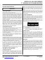
1
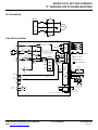
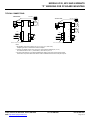
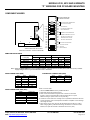
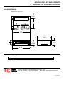
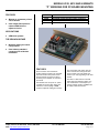
MODELS 4122, 4212 AND VARIANTS
“P” VERSIONS FOR PC BOARD MOUNTING
MODEL
4122P
4212P
4122ZP
4212ZP
FEATURES
•
Mounts on customers printed
circuit boards.
•
Uses output filter option for
reduced PWM noise to
adjacent circuits
FEATURES
+24~90VDC, 10/20A, Standard 0-100% modulation
+24~90VDC, 6/12A, Standard 0-100% modulation
+24~90VDC, 10/20A, 50% modulation
+24~90VDC, 6/12A, 50% modulation
APPLICATIONS
•
OEM drive systems
THE OEM ADVANTAGE
•
Minimize cabling for lowest
cost products
•
Uses industry-standard
connectors for solderless
installation
FEATURES
These versions of the 4122/4212
models and their variants use extended
pins that interface with printed circuit
board mounted connectors for direct
mounting of the amplifier to customers
pc boards.
Pins models also accept the “F” option
card that has output ‘edge’ filters that
reduce the noise coupling of PWM
outputs to adjacent cabling and circuitry.
Copley Controls, 20 Dan Road, Canton, MA 02021
Web: http://www.copleycontrols.com
Tel: 781-828-8090
The output filter card option uses the
same connectors as the popular 300
series models ( 303, 306, 306A and
variants ) for easy upgrading to the 4xx2
models.
The filter is a dual section L/C/R that
slows down the switching ‘edges’ ( the
rise and fall times of the outputs ) for
greatly reduced coupling of PWM noise
to nearby cables and circuits.
Fax:781-828-6547
Page 1 of 1
MODELS 4122, 4212 AND VARIANTS
“P” VERSIONS FOR PC BOARD MOUNTING
FILTER DIAGRAM
R
AMPLIFIER
C2
L
OUT(+)
C1
GND
MOTOR
L
C1
OUT(-)
C2
R
FUNCTIONAL DIAGRAM
* JP1: PINS 2-3 FOR /ENABLE AT J2-11
PINS 1-2 FOR /INHIBIT AT J2-11
INTEGRATOR RESET SWITCHES
TURN ON WHEN AMP IS DISABLED
RH2 100 K
AUX
16
LED
TACH LEAD
TACH (-)
RH4
6
GND
+
11
*JP1
INTEGRATOR
-
10
3 2 1
7
RH3
4
-
REF(-)
5
+
100 K
REF LEAD
RH6
CH8
REF AMP
Gv = 1
REF(+)
CH5
CH9
RH10
(OPEN)
CH11
*
*DEFAULT VALUE OF CH11 IS 0 OHMS
NOTE:
+
SERVO
PREAMP
FOR TORQUE MODE OPERATION
FOR VELOCITY MODE ( BRUSH TACH )
REPLACE CH11 WITH 4.7NF
CURRENT LIMIT
SECTION
+
9
CURRENT
MONITOR
8
GND
2
15
MOMENTARY SWITCH CLOSURE RESETS FAULT
WIRE RESET TO GROUND FOR SELF-RESET
CH14
RH1
10 MEG
J2 SIGNAL CONNECTOR
PEAK
TIME
VALUE DEPENDS ON MODEL
SEE "ARMATURE INDUCTANCE" TABLE
CURRENT
ERROR
AMP
47K
0.47U
OUTPUT
CURRENT
SENSE
Voltage gain = 1
J1 MOTOR & POWER CONNECTOR
PWM
STAGE
MOSFET
"H"
BRIDGE
4.8 kHz FILTER
1
VOLTAGE
GAIN
3
Gv = +HV
10
4
+/-6V at
+/-Ipeak
1K
MOTOR
+
2
+/-6V for
+/-Ipeak
33NF
+FAULT OUTPUT
RESET
+
RH13 4.7MEG
1K
33NF
NEG ENABLE
14
RH15
-15V
CURRENT
REF
12
13
CH16
47K
RH12 182K
+15V
BALANCE
50K
CH17
PEAK
CURRENT
CONT
CURRENT
CW
+5V
STATUS
&
CONTROL
LOGIC
*
ENABLE
POS ENABLE
60.4 K
100PF
RH7 100 K
GREEN = NORMAL
RED = FAULT
GND
5
-
MOTOR +
MOTOR GND
GND
+HV
4.8 kHz FILTER
1K
+HV
+15
AUXILIARY
DC OUTPUTS
-15
1
3
10k
+15V
+5
+15
10k
-15V
DC / DC
CONVERTER
CASE MAY BE GROUNDED
FOR SHIELDING
-15
CASE GROUND
NOT CONNECTED
TO CIRCUIT GROUND
POWER GROUND AND SIGNAL GROUNDS ARE COMMON
Copley Controls, 20 Dan Road, Canton, MA 02021
Web: http://www.copleycontrols.com
Tel: 781-828-8090
Fax:781-828-6547
Page 2 of 2
MODELS 4122, 4212 AND VARIANTS
“P” VERSIONS FOR PC BOARD MOUNTING
TYPICAL CONNECTIONS
TORQUE MODE
ENCODER
VELOCITY MODE
REF+
REF-
4
1
J2
5
ENCODER
+
J1
REF+
MOTOR
2
REF-
4
+
1
J2
J1
5
MOTOR
2
6
J2
+
7
GND
10
ENABLE
11
3
POS ENABLE
12
J1 4
NEG ENABLE
13
5
GND
GND
+
+HV
Note: JP1 on pins 2-3 ( default )
TACH
10
ENABLE
11
POS ENABLE
12
NEG ENABLE
13
3
J1
4
5
GND
+
+HV
Note: JP1 on pins 2-3 ( default )
Notes
1. All amplifier grounds are common (J1-3, J1-4, J2-2, J2-7, and J2-10 )
Amplifier grounds are isolated from case & heatplate..
2. Jumper JP1 default position is on pins 2-3 for ground active /Enable input ( J2-11 )
For /Inhibit function at J2-11 ( +5V enables ), move JP1 to pins 1-2
3. For best noise immunity, use twisted shielded pair cable for reference and tachometer inputs.
Twist motor and power cables and shield to reduce radiated electrical noise from pwm outputs.
Copley Controls, 20 Dan Road, Canton, MA 02021
Web: http://www.copleycontrols.com
Tel: 781-828-8090
Fax:781-828-6547
Page 3 of 3
MODELS 4122, 4212 AND VARIANTS
“P” VERSIONS FOR PC BOARD MOUNTING
CONNECTORS AND PINOUTS
J1: MOTOR & POWER CONNECTIONS
Pin
1
2
3
4
5
Signal
Motor (+)
Motor (-)
GND
GND
+HV
Remarks
Amplifier output to motor (+) winding
Amplifier output to motor (-) winding
Power supply return. Connect to system ground at this pin.
Power supply return. Connect to system ground at this pin.
+HV DC power supply input
J2: AMPLIFIER BOARD CONNECTIONS
Pin
Signal
1
2
3
4
5
6
7
8
9
10
11
+15V
Gnd
-15V
Ref (+)
Ref (-)
Tach (-)
Gnd / Tach (+)
Curr Mon
Curr Ref
Gnd
/Enable
12
/Pos Enab
13
/Neg Enab
14
/Normal
15
/Reset
16
Aux
Remarks
+15V in series with 10kΩ
Signal ground
-15V in series with 10kΩ
Differential input positive terminal for Reference voltage
Differential input negative terminal for Reference voltage
Negative terminal of brush tachometer
Signal ground, or positive terminal of brush tachometer
Output current monitor: ±6V output at ±peak output current
Current demand signal to PWM stage: ±6V demands ±peak current
Signal ground
Amplifier enable input: enables or inhibits PWM switching at outputs
Default: Gnd enables amplifier, open or +5V inhibits ( JP1 @ 2-3 )
For controllers that output +5V to enable amplifier, move internal
jumper JP1 to pins 1-2 ( Gnd will inhibit, +5V or open will enable )
Gnd to enable output current in one polarity, open or +5V to inhibit
Typically used with grounded, normally closed limit switches.
Gnd to enable output current in opposite polarity, open or +5V to
inhibit. Typically used with grounded, normally closed limit switches.
Current-sinking when amplifier enabled and operating normally.
Goes to +5V when amplifier disabled or fault condition exists.
Ground to reset overtemp or output short circuit latching faults.
For automatic reset of faults every 200mS, ground permanently.
Single-ended auxiliary input.
BALANCE POTENTIOMETER
Default position: centered. Functions to bring output current ( in torque mode ) or output velocity ( in tachometer mode ) to zero
with reference input voltage at zero, or control system output at zero. Normal range is ±1% of full scale with 10Meg resistor in
header location RH1. To use the pot as a wide range set-point adjustment, install a 150kΩ resistor at RH1. Now, full CW or CCW
will have the effect of a ±10V signal at the reference inputs.
STATUS LED
Dual color, red/green.
Color
Green
Red
Note
+HV
Normal
Too low or too high
X
X
X
1, 5
/Enable
Active
X
Inhibited
X
X
2, 5
Short
None
X
X
Output short
X
3, 5
Overtemp
Normal
X
X
X
Too hot
4, 5
Notes:
1. +HV normal >20V and <92V for model 4122, >20V and <129V for model 4212
2. /Enable is ground-active for JP1 on pins 2-3 ( default ). To reverse function, switch JP1 to pins 1-2.
3. Shorts detected by overcurrent circuit are between outputs, or from outputs to ground.
4. Overtemperature faults occur when heatplate temperature is >70°C
5. +HV and /Enable cause momentary amplifier shutdown, operation is restored when +HV is within normal limits and /Enable input is
active. Output shorts, and overtemperature faults latch-off amplifier. Thus amplifier will remain off until power is cycled on/off, or /Reset
input is grounded momentarily. If /Reset input is wired to ground, output short and overtemperature faults will self-reset every 200ms.
Copley Controls, 20 Dan Road, Canton, MA 02021
Web: http://www.copleycontrols.com
Tel: 781-828-8090
Fax:781-828-6547
Page 4 of 4
MODELS 4122, 4212 AND VARIANTS
“P” VERSIONS FOR PC BOARD MOUNTING
COMPONENT HEADER
NO PARTS INSTALLED
IN THESE LOCATIONS
CH17
CH16
LOAD INDUCTANCE COMPENSATION
(SEE CHART FOR VALUES)
RH15
JP1
3 2 1
J1
J2
1
5
16
1
COMPONENTS LABELLED "SEL"
ARE NOT INSTALLED AT FACTORY
USER SHOULD SELECT VALUES AS REQUIRED
0.47UF
CH14
PEAK TIME LIMIT
4.7 MEG
RH13
CONTINUOUS CURRENT LIMIT
PEAK CURRENT LIMIT
182K
RH12
(O OHM)
CH11
60.4K
RH10
PREAMP DC GAIN & INTEGRATOR
(SEL)
CH9
PREAMP HI-FREQUENCY ROLL-OFF
(SEL)
CH8
REF INPUT LEAD CAPACITOR
100K
RH7
REFERENCE INPUT SCALING
(SEL)
RH6
REF INPUT LEAD RESISTOR
(SEL)
CH5
(SEL)
RH4
100K
RH3
TACH INPUT SCALING
100K
RH2
AUX INPUT
10MEG
RH1
BALANCE RANGE
TACH INPUT LEAD NETWORK
ARMATURE INDUCTANCE
Model
Load (mH)
0.2 to 0.5
0.6 to 1.7
1.8 to 4.8
5 to 14
15 to 45
RH 15
80.6k
200k
402k
806k
1.5M
4122
CH17
2.2 nF
680 pF
680 pF
680 pF
470 pF
CH16
390 pF
220 pF
180 pF
150 pF
100 pF
RH15
69.8 k
100 k
301 k
698 k
1.21M
4212
CH17
2.2 nF
1 nF
470 pF
330 pF
220 pF
CH16
390 pF
330 pF
100 pF
82 pF
82 pF
Note: Values in bold & italics are factory installed standard. Values shown are for 90V (4122 ) and 125V (4122). At lower
supply voltages RH15 may be increased and CH17 decreased.
PEAK CURRENT LIMIT (AMP)
4122
20
16.7
13.3
10
6.7
3.3
4212
12
10
8
6
4
2
CONTINUOUS CURRENT LIMIT (AMP)
RH12 (Ω)
182k
56k
30k
18k
9.1k
3.9k
CH14 (μF)
0.47
0.33
0.22
0.15
0.10
.047
Copley Controls, 20 Dan Road, Canton, MA 02021
Web: http://www.copleycontrols.com
4212
6
4.4
3.4
RH13 (Ω)
4.7Meg
7.15Meg
10Meg
Notes on Current Limits:
PEAK CURRENT TIME-LIMIT (SEC)
Tpeak
1
0.8
0.5
0.3
0.2
0.1
4122
10
7.4
5.7
1. Values in bold & italics are factory installed standard.
2. Peak times double after polarity reversal.
3. Peak current limit should be set greater than continuous current limit.
If Ipeak < Icont then peak overrides continuous limit and Icont = Ipeak.
Minimum setting for peak current is 0% of peak rating.
4. Continuous current sense is for average current. Symmetrical waveforms with zero
average value may cause overtemperature shutdown of amplifier or motor damage
2
due to high I R losses.
5. Times shown are for 100% step from 0A with default value of RH13 ( 4.7 Meg ).
When changing RH13, peak times will change. Set RH13 for continuous current
limit first, then pick CH14 based on waveforms at Curr Ref ( J2-9 ).
Tel: 781-828-8090
Fax:781-828-6547
Page 5 of 5
MODELS 4122, 4212 AND VARIANTS
“P” VERSIONS FOR PC BOARD MOUNTING
APPLICATION INFORMATION
IMPORTANT! ALWAYS REMOVE POWER WHEN CHANGING
HEADER PARTS!!
OPERATING MODES
These amplifiers operate as either open-loop current sources, or
feedback devices using analog tachometers.
As open-loop current sources, the ±10V at the reference inputs
produce current in the load, typically a motor. The motor acts as
a transducer, and converts current into torque, the twisting force
at the motor shaft. This is called torque mode. It is used most
frequently in systems that have controllers taking feedback from
an encoder on the motor shaft. The computer calculates both
position and velocity from the encoder signal, processes them in
a digital filter, and outputs a signal to the motor causing it to
accelerate or decelerate.
As a feedback amplifier, a signal is generated by an analog brush
tachometer mounted on the motor. This is a generator that
produces an analog signal that has a polarity and amplitude
proportional to the motor speed. The amplifier subtracts the tach
signal from the reference signal, and amplifies the difference
between them. This is called velocity mode, because the
amplifier changes the motor current ( torque ) so that the motor
velocity is proportional to the reference signal.
TORQUE MODE OPERATION
Torque mode is the default configuration. For input voltages of
±10V, the amplifier will output its peak rated current.
In torque mode, motor current is held constant, and motor speed,
or velocity changes as the load changes.
In torque mode the gain of the servo preamplifier is simply 0.6
and scales the ±10V from the reference signal down to the ±6V
that drives the PWM stage.
The servo preamplifier integrator function is disabled, and the low
gain is constant over a wide range of frequencies. Thus we
sometimes call this flat-gain mode.
VELOCITY MODE OPERATION
The difference between the reference and tachometer signals is
amplified and used to change the torque on the motor. Ideally,
the difference between the command and feedback signals would
be zero, so in velocity mode operation the servo preamplifier
must have much higher gain than when in torque mode.
In addition, the gain must change over a range of frequencies.
For “stiffness” that corrects for steady-state changes, the
amplifier uses an integrator. For fast response the loop gain of
the servo preamplifier must be tailored to the characteristics of
the motor and tachometer. To control oscillations from the
tachometer, the gain of the preamplifier must roll-off, or decrease
at higher frequencies.
In velocity mode, motor speed is held constant, while motor
current changes in response to changes in the load.
THE PARTS OF THE AMPLIFIER
DIFFERENTIAL AMPLIFIER
The reference signal ( the command signal from the control
system ) is sensed by a differential amplifier. This acts like a
voltmeter with two probes, measuring a voltage between two
points. Current flowing in the amplifier power wiring causes
voltage drops in the wires resistance. This in turn can produce a
Copley Controls, 20 Dan Road, Canton, MA 02021
Web: http://www.copleycontrols.com
voltage at the amplifier ground that is different than the control
system ground. If this voltage is added to the output of the control
system, it can produce oscillation, or inconsistent operation. To
eliminate this effect, you should always use both reference
inputs.
Connect the Ref(+) input to the output of the controller card, and
the Ref(-) input to ground at the control card. Now, the differential
amplifier will measure the control signal at the control card and
will reject any noise that exists between amplifier and control
system grounds.
THE SERVO PREAMPLIFIER
This section processes the reference signal and any feedback
signals, and generates an internal current reference signal that
controls the PWM stage to produce output currents. It is here that
the reference signal and tachometer signals are compared, and
the difference signal produced and amplified.
Three components on the header control the behavior of the
servo preamp. The chart below lists the default torque-mode and
starting-point values for velocity mode operation:
Part
CH9
RH10
CH11
Torque
out
60.4k
short
Velocity
220pF
680k
4.7nF
CH9 controls the high-frequency roll-off.
RH10 controls the loop gain, and thus the step-response
of the amplifier.
CH11 ( along with RH7 ) forms the integrator that gives the
stiffness at a standstill, or speed regulation while running.
CURRENT LIMITING
This stage takes the output of the servo preamplifier, and
processes it before sending it to the PWM stage. The amplitude
of the signal is first clamped to produce peak current limiting. This
signal then goes to the continuous current-limit circuit where
these functions are produced. Finally, the current-limited signal is
outputted to the PWM stage as the current-reference signal. This
signal is quite useful in that the current limit action can be seen
here and measured without connecting a motor, thus protecting it
from overload during initial setup.
PWM STAGE
The voltage at the output of the current limit stage is called the
current reference. This signal becomes the demand signal that
controls the PWM stage. Here the current demand is converted
into a current in the motor. This current can be measured at the
current monitor, which shows the response of the motor to the
current demand signal. By operating as a current source, the
PWM stage is able to achieve faster response from the motor
than if was acting only as a variable voltage.
The current error amplifier compares the current reference with
the current monitor, and adjusts the output voltage such that the
demanded current flows in the motor. The gain of this amplifier is
controlled by RH15, CH16, and CH17, which are used to
compensate the amplifier for the motors’ inductance.
1)
Tel: 781-828-8090
Fax:781-828-6547
Page 6 of 6
MODELS 4122, 4212 AND VARIANTS
“P” VERSIONS FOR PC BOARD MOUNTING
OUTLINE DIMENSIONS
Dimensions in inches (mm.)
0.56
2.00
4.00
3.00
0.625
1.00
0.16
4.30
ORDERING GUIDE
Model 4122
Model 4212
20A peak, 10A continuous, +22 to +90VDC brush motor amplifier
12A peak, 6A continuous, +22 to 125VDC brush motor amplifier
Copley Controls, 20 Dan Road, Canton, MA 02021, USA
Tel: 781-828-8090
Fax: 781-828-6547 Web: http://www.copleycontrols.com
Rev B, 06/08/2010