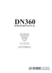
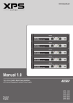
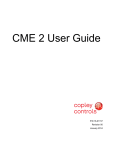
1
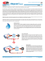
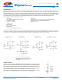
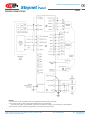
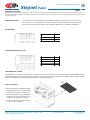
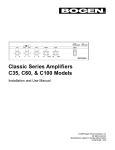
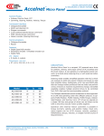
Copley
Controls
Corp.
Stepnet Panel
™
CANopen Stepper Motor Driver
RoHS
Control Modes
• Indexer, Point-to-Point, PVT
• Camming, Gearing
• Position, Velocity, Torque [Servo Mode]
• Position (Microstepping)
Command Interface
• CANopen/DeviceNet
• ASCII and discrete I/O
• Stepper commands
• PWM velocity/torque command
• Master encoder [Gearing/Camming]
Communications
• CANopen/DeviceNet
• RS-232
Feedback
• Digital Quad A/B encoder
I/O - Digital
• 12 inputs, 4 outputs
Dimensions: mm [in]
• 138 x 78 x 39 [5.4 x 3.1 x 1.5]
Model
Ip
Ic
Vdc
STP-075-07
7
5
75
STP-075-10
10
10
75
description
Stepnet is a stepping motor driver that combines CANopen networking with 100% digital control of stepping motors. When used with
Copleys’ Accelnet™ and Xenus™ digital servoamplifiers it makes
possible brushless, brush, and stepping motor control over the
same distributed network.
In Servo Mode, steppers fitted with encoders can be operated as
DC brushless servo motors in current, velocity or position modes.
This enables the motor to operate at higher RPM’s without stalling
which might occur in open-loop operation as a stepper.
Stepnet can operate as a stand-alone driver accepting incremental
position commands from step-motor controllers in Step/Direction
or CU/CD format, as well as A/B quadrature commands from a
master-encoder. Pulse to motor position ratio is programmable for
electronic gearing.
Set up is fast and simple using CME 2™ software operating under
Windows® and communicating with Stepnet via an RS-232 link.
CAN address selection is programmable in flash memory, by rotary
switch on the unit or via programmable digital inputs.
grammable. In PVT (Position-Velocity-Time) mode, the controller
sends out a sequence of points each of which is an increment of a
larger, more complex move than that of a single index or profile.
The driver then uses cubic polynomial interpolation to “connect
the dots” such that the motor reaches each point (Position) at the
specified velocity (Velocity) at the prescribed time (Time). Homing
mode is configurable to work with a combination of limit and home
switches such that the driver moves the motor into a position that
has an absolute reference to some part of the machine. Profile
Velocity mode controls velocity, acceleration, and deceleration with
no target position defined.
There are twelve logic inputs. Input [IN1] is dedicated for driver
Enable. Eleven are programmable as limit or home switches,
stepper pulse inputs, A/B encoder, reset, CAN address, or motor
overtemperature sensor. There are four programmable logic outputs
for reporting a driver fault, operating a motor-mounted brake, or
other status indications. When operating as a node on a CANopen
network, the inputs and outputs can be read or controlled as independent I/O points that are not linked to driver operation.
Stepnet operates as a Motion Control Device under the DSP-402
protocol of the CANopen DS-301 V4.01 (EN 50325-4) application
layer. DSP-402 modes supported include: Profile Position, Profile Velocity, Interpolated Position Mode (PVT), and Homing Modes. When
operating in Servo Mode , Profile Torque mode is available.The CAN
bus interface is optically isolated from the driver circuits.
An Aux HV input is provided for “keep alive” power that preserves
the driver data (e.g. current position) and CANopen operation if +HV
has been removed as in an emergency-stop situation. This enables
the control system to monitor drive status and to enable an orderly
recovery without a full system reset, and homing of all axes.
Profile Position mode does a complete motion index on command
with acceleration & deceleration, top speed, and distance pro-
Operation from transformer-isolated DC power supplies saves cost
in multi-axis systems.
Copley Controls Corp., 20 Dan Road, Canton, MA 02021, USA
Web: www.copleycontrols.com
Tel: 781-828-8090 Fax: 781-828-6547
Page 1 of 14
Copley
Controls
Corp.
CANopen Stepper Motor Driver
Stepnet Panel
™
RoHS
GENERAL SPECIFICATIONS
Test conditions: Load = 1mH per phase, ambient temperature = 25 °C. +HV = HVmax
MODEL
STP-075-07 STP-075-10
Output Power
Peak Current
7 (5)
10 (7)
Adc (Arms, sinusoidal)
Peak time
1
1
s
Continuous current
5 (3.54)
10 (7)
Adc (Arms, sinusoidal)
INPUT POWER
HVmin to HVmax
+20 to +75
+20 to +75
Vdc,transformer-isolated
Ipeak
8
11
Adc (1 sec)
Icont
5.5
11
Adc
Aux HV
+20 to +75
+20 to +75
Vdc
current control
Current loop update rate
15 kHz (66.7 µs)
PWM outputs
Dual MOSFET H-bridges, 15 kHz center-weighted PWM, space-vector modulation
PWM ripple frequency
30 kHz
HV Compensation
Changes in HV do not affect current-loop bandwidth
Reference inputs
CAN bus
Operating Modes
Profile Position, Profile Velocity, Interpolated Position,
and Homing modes. Profile Torque when in Servo Mode
Digital position reference
Step/Direction, CountUp/CountDown Stepper command pulses ( 1 MHz maximum rate )
Quad A/B Encoder
5 Mline/sec, 20 Mcount/sec (after quadrature)
Digital torque or velocity reference (Servo mode only)
PWM/polarity or 50% PWM format
DIGITAL inputs (Note 1)
Quantity
12
Enable [IN1]
Dedicated input for driver enable, 33 µs RC filter, 10 kΩ pull-up/down to +5/ground
GP [IN2,3,4,5]
General Purpose inputs with 33 µs RC filters (22 µs for [IN5]), programmable functions
and active level select, 10 kΩ pull-up/down to +5/ground, Vin = 0 to +30 Vdc
HS [IN6,7,8,9,10,11,12]
High-Speed Inputs inputs with 100 ns RC filters, programmable functions, and active level select
10 kΩ pull-up/down to +5/ground, Vin = 0 to +12 Vdc
All inputs
74HC14 Schmitt trigger operating from +5.0 V with RC filter on input, 10 kΩ pull-up/down to +5/ground
RC time-constants assume active drive on inputs and do not include 10 kΩ resistors
Logic levels
Vin-LO < +1.35 Vdc, Vin-HI > +3.65 Vdc
digital outputS
Quantity
4
Type
Current-sinking MOSFET open-drain outputs with
1 kΩ pullup to +5 Vdc through diode, 1 Adc sink max, +30 Vdc max.
Functions
Programmable with CME 2™
Active Level
Programmable to either HI (off, pull-up to +5 Vdc) or LO (on, current-sinking) when output is active
RS-232 COMMUNICATION PORT
Signals
RxD, TxD, Gnd
Full-duplex, serial communication port for driver setup and control, 9,600 to 115,200 Baud
CANopen COMMUNICATION PORTS
Number
Two, optically-isolated from driver circuits
Signals
CANH, CANL, Ground, 1 Mbit/sec maximum
Protocol
CANopen Application Layer DS-301 V4.01
DSP-402 Device Profile for Drives and Motion Control
motor connections
Motor A+,A-,B+,B-
Outputs to 2-phase stepper motor, bipolar drive connected
Motemp
Motor temperature sensor or switch. Any input [IN2~IN12] can be programmed for this function
Encoder
Quadrature encoder for stall-detection or servo-mode operation
protections
HV Overvoltage
> +91 Vdc
Driver outputs turn off until +HV is < overvoltage
HV Undervoltage
< +20 Vdc
Driver outputs turn off until +HV >= +20 Vdc
Driver over temperature
PC Board > 70 °C.
Programmable actions
Short circuits
Output to output, output to ground, internal PWM bridge faults
2
I T Current limiting
Programmable: continuous current, peak current, peak time
Latching / Non-Latching
Programmable
AGENCY CONFORMANCE
EN 55011 : 1998
CISPR 11 (1997) Edition 2/Amendment 2:
Limits and Methods of Measurement of Radio Disturbance Characteristics of
Industrial, Scientific, and Medical (ISM) Radio Frequency Equipment
EN 61000-6-1 : 2001
Electromagnetic Compatibility Generic Immunity Requirements
Following the provisions of EC Directive 89/336/EEC:
EN 60204-1: 1997
Safety of Machinery. Electrical Equipment of Machines
Following the provisions of EC Directive 98/37/EC:
UL 508C : 1996
UL Standard for Safety for Power Conversion Equipment
Notes
1. [IN1] is not programmable and always works as driver Enable. Other digital inputs are programmable.
Copley Controls Corp., 20 Dan Road, Canton, MA 02021, USA
Web: www.copleycontrols.com
Tel: 781-828-8090 Fax: 781-828-6547
Page 2 of 14
Copley
Controls
Stepnet Panel
™
Corp.
CANopen Stepper Motor Driver
RoHS
FEATURES
Stepnet is a DSP based driver for two-phase step motors that operates as a node on a CAN bus or as a stand-alone driver that takes step
motor pulses to command motor position. It operates from line-isolated DC power supplies.
As a CAN node it operates under the CANopen protocol DSP-402 for motion control devices. The functions supported include Profile
Position, Profile Velocity, Interpolated Position, and Homing Modes. In Profile Position Mode a single PDO (Process Data Object) can
command a position profile with programmable acceleration, deceleration, maximum speed, and target position. The acceleration can be
trapezoidal or S-curve. Interpolated Position Mode works with multiple PDO’s each of which specifies position, velocity, and time. For this
reason this mode is sometimes called PVT (Position, Velocity, Time) mode. The driver uses a cubic-interpolation algorithm to connect the
PVT points such that the motor satisfies the PVT parameters at each point while moving along a path that connects the points smoothly.
In PVT mode long moves of complex shapes can be performed. Profile Velocity mode has controlled acceleration, deceleration, and
maximum velocity for speed control application with no defined positions. Profile Torque mode is available when the stepper is operated
in Servo Mode.
Multiple axes can be synchronized so that moves are coordinated. This emulates the functions normally performed by motion-controller
cards or chips which can now be eliminated in many cases reducing cost and system complexity.
Stepnet also operates as a stand-alone driver taking pulses from controllers that output pulses in the Step/Direction or Count-Up/CountDown mode. Electronic gearing is supported when the position commands come from a quadrature encoder. The ratio of encoder counts
at the inputs to microsteps at the motor is programmable.
MICROSTEPPING
Step motors can be viewed as brushless motors with a large number of poles, or electrical
cycles per revolution. The two windings are spaced at 90 electrical degrees. Reversing the
currents in each winding produces a 180 degree phase shift. The result is full-stepping. This
kind of operation can be noisy and the large angular change per step excites the rotor to
produce undesirable vibrations. In microstepping, the phase currents are sinusoidal and the
change in electrical angle per step can be programmed such that the motor moves with less
noise and vibration.
Stepnet
Stepper
+
STALL DETECTION
Adding an encoder to the motor gives position feedback to the driver.
When the measured movement of the motor differs from the commanded position by an amount that is programmable a motor stall is
indicated. The driver can then signal the control system that a motor
stall has occurred, or can send a message over the CAN bus with the
same effect. In this mode the stepper is operated in open-loop mode
where the driver changes the phase currents based on the commanded
position of the motor.
Encoder
-
Stall?
Stepnet
Stepper
Encoder
+
-
Copley Controls Corp., 20 Dan Road, Canton, MA 02021, USA
Web: www.copleycontrols.com
SERVO MODE
The stepper motor is now operated as a brushless servo
motor. Motor phase currents are adjusted dynamically in
response to the difference between commanded position
and motor position as fed back by the encoder. Field-oriented control (vector control) of the motor currents gives
a wider range of motor speeds without the possibility of
stalling. If the load exceeds motor’s capability excess
following error can be detected and driver programmed
to take appropriate action.
Tel: 781-828-8090 Fax: 781-828-6547
Page 3 of 14
Copley
Controls
Corp.
Stepnet Panel
™
CANopen Stepper Motor Driver
CME 2™ SOFTWARE
Driver setup is fast and easy using CME 2™ software. All of the operations needed to
configure the driver are accessible through this powerful and intuitive program.
Motor data can be saved as .ccm files. Driver data is saved as .ccx files that contain
all driver settings plus motor data. This eases system management as files can be
cross-referenced to ampifiers.
Once an driver configuration has been completed systems can be replicated easily with
the same setup and performance.
RoHS
RS-232 communication
Stepnet is configured via a three-wire, full-duplex RS-232 port that operates from 9,600
to 115,200 Baud. CME 2™ software provides a graphic user interface (GUI) to set up
all of Stepnet features via a computer serial port.
Once configured, Stepnet can be used in stand-alone mode, or as a networked driver
on a CAN bus.
CANopen COMMUNICATIONS
Stepnet drivers employ the CAN physical layer which defines the signals, voltage levels, and connections. Once connected as a node
on a CAN (Controller Area Network) they communicate using the CANopen protocol which defines the format of the data flowing over
the bus. The CAN transceiver circuit and local +5 Vdc supply are optically isolated from the driver circuits.
J5 & J6 pins 1,2,3, and 7 are wired to conform to CiA DR-303-1 section 6.4 “RJ45 connector”. Pin 4 designated “reserved” in DR303-1 is not connected. Pin 8 of J5 & J6 are inter-connected for systems that carry CAN_V+ power. This enables this power to pass
through the driver to other equipment on the CAN. Pin 6, CAN_SHLD connects between J5 & J6 to continue this connection through
to other equipment.
CAN status LED
DRIVER status LED
A single bi-color LED gives the state of the driver by changing color, and either blinking or remaining solid.
The possible color and blink combinations are:
• Green/Solid: Driver OK and enabled. Will run in response to reference inputs or CANopen commands.
• Green/Slow-Blinking: Driver OK but NOT-enabled.
Will run when enabled.
• Green/Fast-Blinking: Positive or Negative limit switch active. Driver will only move in direction not inhibited by limit switch.
• Red/Solid: Transient fault condition.
Driver will resume operation when fault is removed.
• Red/Blinking: Latching fault.
Drive Fault conditions:
Operation will not resume until amp is Reset
• Over or under-voltage
• Motor over-temperature
• Encoder +5 Vdc fault
• Short-circuits from output to output
• Short-circuits from output to ground
• Internal short circuits
• Driver over-temperature
• Following error
Faults are programmable to be either transient or latching
Copley Controls Corp., 20 Dan Road, Canton, MA 02021, USA
Web: www.copleycontrols.com
Tel: 781-828-8090 Fax: 781-828-6547
Page 4 of 14
Copley
Controls
Corp.
CANopen Stepper Motor Driver
Stepnet Panel
™
RoHS
Stand-Alone Mode POSITION-CONTROL Inputs
Stepnet works with motion controllers that output pulses to command position. These formats are supported:
Step/Direction
CU/CD
A/B Quadrature Encoder
In Step/Direction, a pulse-train controls motor position, and the direction is controlled by a DC level at the Direction input.
CU/CD (Count-Up/Count-Down) turns the motor CW or CCW depending on which input the pulse-train is directed to.
The motor can also be operated in an electronic gearing mode by connecting the inputs to an encoder on another motor.
In all cases the ratio between input pulses and motor revolutions is programmable.
Step/Direction Inputs
Count-up/Count-down Inputs
QUAD A/B Encoder Inputs
Stand-Alone Mode Torque & Velocity Inputs (SERVO MODE ONLY)
A digital PWM signal controls magnitude, and a DC signal controls polarity..
MOTOR CONNECTIONS
The only motor connections required for stepper operation are the motor phases. These carry the driver output currents that drive the
motor to produce motion. The feedback encoder, brake, and motor over-temperature sensors are optional. If stall-detection is desired in
stepper operation the encoder is required. When operating a stepper as a servo-motor the encoder is also required.
motor phase connections
The driver output is a dual H-bridge that
converts the DC buss voltage (+HV) into
sinusoidal voltage waveforms that drive the
motor phases. Cable should be sized for the
continuous current rating of the driver. Motor
cabling should use twisted, shielded conductors for CE compliance, and to minimize
PWM noise coupling into other circuits.
Motor Encoder
Six dedicated inputs accept the encoder A,
B, and X (index) signals. Encoders with differential line-driver outputs must be used.
Motor Brake
Digital outputs [OUT1,2,3,4] can be programmed to power a motor-mounted brake.
These brake the motor when they are in
an unpowered state and must have power
applied to release. This provides a fail-safe
function that prevents motor motion if the
system is in an unpowered (uncontrolled)
state. Because brakes are inductive loads,
an external flyback diode must be used
to control the coil voltage when power is
removed. The timing of the brake is programmable.
Motor Temperature Sensor
Digital input [IN5] is programmable for use with a
motor overtemperature switch. The input should
be programmed as a pull-up to +5 Vdc if the motor
switch is grounded.
Copley Controls Corp., 20 Dan Road, Canton, MA 02021, USA
Web: www.copleycontrols.com
Tel: 781-828-8090 Fax: 781-828-6547
Page 5 of 14
Copley
Controls
Corp.
Stepnet Panel
™
CANopen Stepper Motor Driver
RoHS
digital INPUTS
Stepnet has twelve digital inputs, eleven of which have programmable functions. Input [IN1] is not programmable and is dedicated to
the driver Enable function. This is done to prevent accidental programming of the input in such a way that the controller could not shut it
down.
Two types of RC filters are used: GP (general purpose) and HS (high speed). Input functions such as Step/Direction, CW/CCW, Quad A/B
are wired to inputs having the HS filters, and inputs with the GP filters are used for general purpose logic functions, limit switches, and the
motor temperature sensor. All inputs have programmable debounce time for reliable operation with electromechanical relays.
Programmable functions of the digital inputs are:
•
•
•
•
•
•
•
•
GP inputs HS inputs
Amp enable (dedicated function on [IN1]
• Step & Direction, or CU/CD step motor position commands
Positive Limit switch
• Quad A/B master encoder position commands
Negative Limit switch
• PWM Sync input
Home switch
Driver Reset
Motor over-temperature
Motion abort
CAN address bits (IN7~IN10 only)
In addition to the active level and function for each programmable input, the input resistors are programmable in four groups to either pull
up to +5 Vdc, or down to ground. Grounded inputs with HI active levels interface to PLC’s that have PNP outputs that source current from
+24 Vdc sources. Inputs pulled up to +5 Vdc work with open-collector, or NPN drivers that sink current to ground.
GP Inputs 1,2,3
GP Inputs 4,5
HS Inputs 6,7,8
HS Inputs 9,10,11,12
Note: 4.99 k input resistor on [IN5] is for
compatibility with over-temperature sensors
on Copley Motion Systems ThrustTube
linear motors
DIGITAL OUTPUTS
Digital outputs are open-drain MOSFETs with 1 kΩ pull-up resistors to +5 Vdc. These can
sink up to 1 Adc from external loads operating from power supplies to +30 Vdc. When driving
inductive loads such as a motor brake, an external fly-back diode is required. The diode in
the output is for driving PLC inputs that are opto-isolated and connected to +24 Vdc. The
diode prevents conduction from +24 Vdc through the 1 kΩ resistor to +5 Vdc in the driver.
This could turn the input on, giving a false indication of the driver output state.
These outputs are programmable to be on or off when active. Typical functions are driver
fault indication or motor brake operation. Other functions are programmable.
Copley Controls Corp., 20 Dan Road, Canton, MA 02021, USA
Web: www.copleycontrols.com
Tel: 781-828-8090 Fax: 781-828-6547
Page 6 of 14
Copley
Controls
Corp.
Stepnet Panel
GROUNDING CONSIDERATIONS
Power and control circuits in Stepnet share
a common circuit-ground (Gnd on J1-4,
Signal Ground on J3-7 & 25 and J4-3 & 4).
Input logic circuits are referenced to Signal
Ground, as are power GND, digital outputs,
and encoder. For this reason, driver Gnd
terminals should connect to the users’ common ground system so that signals between
driver and controller are at the same common potential, and to minimize noise. The
system ground should, in turn, connect to
an earthing conductor at some point so that
the whole system is referenced to “earth”.
The CAN ports are optically isolated from
the driver circuits.
Because current flow through conductors
produces voltage-drops across them, it is
best to connect the driver HV GND to system
earth, or circuit-common through the shortest
path, and to leave the power-supply floating.
In this way, the power supply (-) terminal
connects to ground at the driver HV Return
terminals, but the voltage drops across the
cables will not appear at the driver ground,
but at the power supply negative terminal
where they will have less effect.
For CE compliance driver cables should
be shielded. Motor phase currents are balanced, but currents can flow between the
PWM outputs, and the motor cable shield.
™
CANopen Stepper Motor Driver
RoHS
To minimize the effects of these currents
on nearby circuits, the cable shield should
connect to Frame Gnd (J2-1). Power supply
wiring should also be shielded and shield
connected to J1-1, and pin 9 of J3 connects
the control cable shield to frame ground. The
driver case (Frame Ground, or F.G.) does not
connect to any driver circuits. Connections to
F.G. are provided on connectors J1-1, J2-1,
and J3-9. When installed, the driver case
should connect to the system chassis. This
maximizes the shielding effect of the case,
and provides a path to ground for noise currents that can occur in the cable shields.
Signals from controller to driver are referenced to +5 Vdc, and other power supplies
in user equipment. These power supplies
should also connect to system ground and
earth at some point so that they are at same
potential as the driver circuits. The final
configuration should embody three current-carrying loops. First, the power supply
currents flowing into and out of the driver
at the +HV and Gnd pins on J1. Second
the driver outputs driving currents into and
out of the motor phases, and motor shield
currents circulating between the A+, A-,
B+, & B- outputs and Gnd. And, lastly, logic
and signal currents connected to the driver
control inputs and outputs.
POWER Supplies
Stepnet operates typically from transformerisolated, unregulated DC power supplies.
These should be sized such that the maximum output voltage under high-line and noload conditions does not exceed the drivers
maximum voltage rating. Power supply rating depends on the power delivered to the
load by the driver. Unlike servo motors that
consume little power at a standstill, steppers
dissipate power continuously when in-position. This can vary from full rated current in
both windings to something less based on
programmed value of holding current.
Power supplies should be chosen with continuous power ratings that are sufficient for
the motor in use.
Operation from regulated switching power
supplies is possible if a diode is placed
between the power supply and driver to
prevent regenerative energy from reaching
the output of the supply. If this is done, there
must be external capacitance between the
diode and driver.
AUXILIARY HV POWER
Stepnet has an input for AUX HV. This is
a voltage that can keep the driver communications and feedback circuits active when
the PWM output stage has been disabled
by removing the main +HV supply. This
can occur during EMO (Emergency Off)
conditions where the +HV supply must be
removed from the driver and powered-down
to ensure operator safety. The AUX HV input
operates from any DC voltage that is within
the operating voltage range of the driver and
powers the DC/DC converter that supplies
operating voltages to the driver DSP and
control circuits.
When the driver +HV voltage is greater than
the AUX-HV voltage it will power the DC/DC
converter. Under these conditions the AUXHV input will draw no current.
Copley Controls Corp., 20 Dan Road, Canton, MA 02021, USA
Web: www.copleycontrols.com
Tel: 781-828-8090 Fax: 781-828-6547
Page 7 of 14
Copley
Controls
Corp.
Stepnet Panel
™
CANopen Stepper Motor Driver
RoHS
driver connections
Notes
1. The functions of input signals [IN2~IN12] are programmable. Default functions are shown.
2. The function of [IN1] on J3-3 is always Driver Enable and is not programmable.
The active level of [IN1] is programmable, and resetting the driver with changes on the enable input is programmable.
3. The functions of [OUT1~OUT4] are programmable. The functions shown are typical.
Copley Controls Corp., 20 Dan Road, Canton, MA 02021, USA
Web: www.copleycontrols.com
Tel: 781-828-8090 Fax: 781-828-6547
Page 8 of 14
Copley
Controls
Corp.
CANopen Stepper Motor Driver
Stepnet Panel
™
RoHS
CONNECTORS & SIGNALS
J3 Cable Connector:
26-Position, Sub-D, three-row
Solder-Cup:
Connector: Norcomp, Inc. PN: 180-026-102-001 (or equivalent), Backshell: Century Interconnect PN: CHS15B (or equivalent)
Poke & crimp:
Connector: Norcomp, Inc. PN: 180-026-172-000 (or equivalent), Contacts: Norcomp, Inc. PN: 180-001-170-001 (or equivalent)
Backshell: Century Interconnect PN: CHS15B (or equivalent)
Cable: 26 conductor, shielded
J3 SIGNALS PIN PIN J3 SIGNALS
J3 SIGNALS PIN
Output 4 [OUT4]
18
9
Frame ground
Output 3 [OUT3]
26
Output 2 [OUT2]
17
8
[OUT1] Output 1
Signal ground
25
Encoder +5 Vdc
16
7
Signal ground
Encoder input /X
24
Encoder input /B
15
6
Encoder input /A
Encoder input X
23
Encoder input B
14
5
Encoder input A
Programmable input [IN12]
22
Programmable input [IN8]
13
4
[IN4] Programmable Input
Programmable input [IN11]
21
Programmable input [IN7]
12
3
[IN3] Programmable Input
Programmable input [IN10]
20
Programmable input [IN6]
11
2
[IN2] Programmable Input
Programmable input [IN9]
19
Programmable input [IN5]
10
1
[IN1] Enable
J4 Cable Connector:
RJ-11 style, male, 6 position Cable: 6-conductor modular type
J4 SIGNALS
1
RxD Input
2
Signal Ground
3
Signal Ground
4
TxD Output
5
No connect
6
Pin
1
8
CAN_GND
7
(CAN_SHLD) 1
6
(CAN_V+)
CAN signals within
dashed line
are isolated
from amplifier
See J4-J5 Notes
Pin
No connect
J5,J6 SIGNALS
Reserved
PIN
J2
J3
J2 SIGNALS
1
Frame Ground
2
Motor B-
3
Motor B+
4
Motor A-
5
Motor A+
J2 Cable Connector:
Molex: 39-01-4051 backshell
Molex: 39-00-0039 contact (5)
Cable: AWG 18
J4
J5
J6
J1
PIN
J1 SIGNALS
1
Frame Ground
1
5
No connection
4
2
Aux HV
CAN_GND
3
3
+HV Input
CAN_L
2
4
GND
CAN_H
1
J4, J5 Cable Connector:
RJ-45 style, male, 8 position Cable: 8-conductor modular type
S1
J1 Cable Connector:
F.G.
Molex: 39-01-4041 backshell
Molex: 39-00-0039 contact (4)
Cable: AWG 18
Frame ground via
tapped hole in heatplate
J4-J5 Notes
1. These signals interconnect between J4 & J5 but have no internal connections to the driver
2. CAN circuits are optically-isolated from driver circuits Copley Controls Corp., 20 Dan Road, Canton, MA 02021, USA
Web: www.copleycontrols.com
Tel: 781-828-8090 Fax: 781-828-6547
Page 9 of 14
Copley
Controls
Corp.
CANopen Stepper Motor Driver
Stepnet Panel
™
RoHS
CANopen CONFIGURATION
Multiple drivers are connected as nodes
on a CAN bus
Individual drivers are configured using
an RS-232 connection and CME 2™
software
CANopen Network Kit(2)
STP-NK
Serial Cable Kit (1)
SER-CK
CAN Network Cable (3)
STP-NC-10 (10 ft)
STP-NC-01 (1 ft)
CAN Terminator (2)
(for last node on CAN bus)
+HV, Motor,
& Control
Connector Kit
STP-CK
Notes:
1. Only one SER-CK is needed per installation
2. CANopen Network Kit STP-NK includes Sub-D 9 to RJ-45
adapter, 10 ft. modular cable, and CAN bus terminator
3. Order one cable (1 or 10 ft) for each additional driver
PART
NuMBER
DESCRIPTION
STP-075-07
Stepnet CANopen Stepper Driver 5/7 Adc @ 75 Vdc
STP-075-10
Stepnet CANopen Stepper Driver 10/10 Adc @ 75 Vdc
STP-CK
Connector Kit for Stepnet (J1 & J2 connector shells & crimp
contacts ,and plug with soldercups & backshells for J3)
STP-NK
CANopen Network Kit
STP-HK
Heatsink Kit (for field installation)
STP-CV
DB-9 Female to RJ45 Adapter Assembly
STP-NC-10
CAN network cable, 10 ft (3 m)
STP-NC-01
CAN network cable, 1 ft (0.3 m)
STP-NT
CAN Network Terminator
CME 2
CME 2™ CD (CME 2™, Manual)
SER-CK
Serial Cable Kit
Power Supply
+HV
+HV
Aux HV
Mains-isolated DC
Required for all systems
User-supplied
Aux HV Power Supply
(Optional)
Copley Controls Corp., 20 Dan Road, Canton, MA 02021, USA
Web: www.copleycontrols.com
STP-HK
Heatsink
(Optional)
Tel: 781-828-8090 Fax: 781-828-6547
Page 10 of 14
Copley
Controls
Corp.
Stepnet Panel
™
CANopen Stepper Motor Driver
RoHS
STAND-ALONE CONFIGURATION
Stepper Motor Control Signals:
Step/Direction
CU/CD
Electronic Gearing Signals:
A/B Quadrature encoder
CME 2™ is used for setup and
configuration.
Serial Cable Kit (1)
SER-CK
+HV, Motor,
& Control
Connector Kit
STP-CK
Notes:
1. Only one SER-CK is needed per installation
PART
NuMBER
DESCRIPTION
STP-075-07
Stepnet CANopen Stepper Driver 5/7 Adc @ 75 Vdc
STP-075-10
Stepnet CANopen Stepper Driver 10/10 Adc @ 75 Vdc
STP-CK
Connector Kit for Stepnet (J1 & J2 connector shells & crimp
contacts ,and plug with soldercups & backshells for J3)
CME 2
CME 2™ CD (CME 2™, Manual)
SER-CK
Serial Cable Kit
STP-HK
Heatsink Kit (for field installation)
Power Supply
+HV
Aux HV
Mains-isolated DC
Required for all systems
User-supplied
Aux HV Power Supply
(Optional)
Copley Controls Corp., 20 Dan Road, Canton, MA 02021, USA
Web: www.copleycontrols.com
STP-HK
Heatsink
(Optional)
Tel: 781-828-8090 Fax: 781-828-6547
Page 11 of 14
Copley
Controls
Corp.
Stepnet Panel
™
CANopen Stepper Motor Driver
RoHS
POWER DISSIPATION
The chart on this page shows the internal power dissipation for Stepnet under differing power supply and output current conditions. The
output current is calculated from the motion profile, motor, and load conditions. The values on the chart represent the rms (root-meansquare) current that the amplifier would provide during operation. The +HV values are for the average DC voltage of the power supply.
When +HV and driver output current are known, the amplifier power dissipation can be found from the charts. The next step is to determine
the temperature rise the driver will experience when it’s installed. For example, if the ambient temperature in the enclosure is 40 °C, and
the heatplate temperature is to be limited to 65 °C to avoid shutdown, the rise would be 25 °C above ambient.
Divide the temperature rise by the power dissipation will yield a result in units of °C/W. For a Stepnet operating at 75 Vdc and outputting
5 Arms, the dissipation would be about 6.6 W. This would give 25 °C/6.6W, or 3.8 °C/W as the maximum thermal resistance (Rth) of a
heatsink.
From the tables on the opposite page it can be seen that Stepnet will work in this application without heatsink or forced-air cooling.
Copley Controls Corp., 20 Dan Road, Canton, MA 02021, USA
Web: www.copleycontrols.com
Tel: 781-828-8090 Fax: 781-828-6547
Page 12 of 14
Copley
Controls
Corp.
Stepnet Panel
™
CANopen Stepper Motor Driver
RoHS
Mounting & Cooling
Stepnet has slots for mounting to panels at 0° or 90°. Cooling is by conduction from driver heatplate to mounting surface, or by convection to ambient.
A heatsink (optional) is required for the driver to deliver the rated continuous output current. Depending on the driver mounting and cooling means this
may not be required.
HEATSINK OPTIONS
Rth expresses the rise in temperature of the amplifier per Watt of internal power loss. The units of Rth
are °C/W, where the °C represent the rise above ambient in degrees Celsius. The data below show
thermal resistances under convection, or fan-cooled conditions for the no-heatsink and heatsink.
NO HEATSINK
NO hEATSINk
°C/w
CONVECTION
2.8
FORCE AIR (100 LFM)
1.3
STANDARD HEATSINK (STP-HS)
STP-hS hEATSINk
°C/w
CONVECTION
<tbd>
FORCE AIR (100 LFM)
0.8
FORCE AIR (200 LFM)
0.6
HEATSINK INSTALLATION
The heatsink is mounted using the same type of screws used to mount the driver to a panel. Phase change material (PSM) is used in
place of thermal grease. This material comes in sheet form and changes from solid to liquid form as the driver warms up. This forms an
excellent thermal path from driver heatplate to heatsink for optimum heat transfer.
PSM
STEPS TO INSTALL
1. Place the PSM on the Stepnet aluminum
heatplate taking care to center the PSM
holes over the holes in the driver body.
2. Mount the heatsink onto the PSM again
taking care to see that the holes in the
heatsink, PSM, and driver all line up.
3. Torque the #6-32 mounting screws to
8~10 lb-in (0.9~1.13 N·m).
Copley Controls Corp., 20 Dan Road, Canton, MA 02021, USA
Web: www.copleycontrols.com
Tel: 781-828-8090 Fax: 781-828-6547
Page 13 of 14
Copley
Controls
Corp.
Stepnet Panel
™
CANopen Stepper Motor Driver
RoHS
MASTER ORDERING GUIDE
Part Number
Description
STP-075-07
Stepnet CANopen Stepper Drive 5/7 Adc @ 75 Vdc
STP-075-10
Stepnet CANopen Stepper Drive 10/10 Adc @ 75 Vdc
Connector kit: J1 & J2 connector shells and crimp contacts, and J3
STP-CK
plug with soldercups and backshell
CANopen Network Kit: D-Sub 9F to RJ-45 adapter, 10 ft (3 m) CANo-
STP-NK
pen RJ-45 (Ethernet) cable and CAN network terminator
STP-NC-10
CANopen RS-45 (Ethernet) cable, 10 ft (3 m)
STP-NC-01
CANopen RS-45 (Ethernet) cable, 1 ft (0.3 m)
STP-CV
CANopen D-Sub 9F to RJ-45 adapter
STP-NT
CANopen Network Terminator
SER-CK
Serial Cable Kit (1 per computer) for CME2
CME2
CME2 CD-ROM
Ordering Instructions
Example: Order 1 STP-075-07 driver with heatsink
installed at factory and associated components
for operation as a CANopen driver:
Qty Item
Remarks
1
STP-075-07-H
Stepnet™ stepper driver
with heatsink
1
STP-CK
Connector Kit
1
STP-NK
CANopen network kit
1
SER-CK
Serial Cable Kit
1
CME2
CME 2™ CD
Heatsink kit for field installation (add “-H” to driver part number to
STP-HK
have heatsink mounted to driver at factory)
DIMENSIONS
5.38 (136.5)
5.08 (128.9)
0.52 (13.2)
Dimensions shown in inches (mm).
2.00
(50.8)
0.16
(4.1)
0.15 (3.8)
Weights: Amplifier 0.94 lb (0.43 kg)
Heatsink 0.4 lb (0.15 kg)
6 places
3.13 (79.4)
0.19 (4.8)
5.00 (127)
0.1 (2.54)
0.16
(4.1)
1.49 [37.8]
0.84 [21.3]
0.187 [47.5]
0.66 (16.76)
RoHS Compliance
Models with the green leaf symbol on the
label are RoHS compliant.
Stepnet Panel V5.01_fr 03/21/2008
Note: Specifications subject to change without notice
Copley Controls Corp., 20 Dan Road, Canton, MA 02021, USA
Web: www.copleycontrols.com
Tel: 781-828-8090 Fax: 781-828-6547
Page 14 of 14