1
CONVOTHERM
OES OEB OGS OGB
easyTOUCH
ENG
Installation manual
Table of Contents
Installation manual
2
Table of Contents
Table of Contents
1
2
3
General information
5
Identifying your combi steamer
About this installation manual
6
7
Design and function
9
Intended use of your combi steamer
Design and function of the combi steamer
10
11
For your Safety
14
Basic safety code
Warning signs on the combi steamer
Hazards and safety precautions
Safety devices
Requirements to be met by personnel, working positions
4
Conveying and setting up the appliance
Dimensions, summary
Requirements for the installation location
Taking to the installation location
Unpacking
Setting up the appliance
5
Connecting up the combi steamer
Electrical installation
Energy optimization system
Water intake
Water drain
Gas installation to a fixed connection on OGS/OGB appliances
Gas installation for liquid gas bottles on OGS/OGB appliances
Flue gas removal system for OGS/OGB appliances
Safety precautions for gas appliances
Approvals
6
Preparing for use
Optional equipment
23
24
27
29
31
33
34
36
37
40
44
47
51
54
55
57
59
60
CONVOClean automatic interior oven cleaning system
Ship model
Grill version
Stacking kit
Communications interface
Extractor hood/condensation hood
Installation manual
22
56
Procedure for preparing the appliance for use
Taking out of service and disposal
7
15
16
18
19
21
3
61
64
65
67
68
69
Table of Contents
8
8.1
8.2
9
Technical data, dimensional drawings and connection
diagrams
70
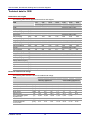
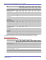
Technical data
Technical data for OEB
Technical data for OES
Technical data for OGS
Technical data for OGB
Technical data for accessories
Dimensions, dimensional drawings and connection diagrams
Dimensions, summary
OES/OEB 6.10
OES/OEB 6.20
OES/OEB 10.10
OES/OEB 10.20
OES/OEB 12.20
OES/OEB 20.10
OES/OEB 20.20
OGS 6.10
OGS 6.20
OGS 10.10
OGS 10.20
OGS 12.20
OGS 20.10
OGS 20.20
OGB 6.10
OGB 6.20
OGB 10.10
OGB 10.20
OGB 12.20
OGB 20.10
OGB 20.20
71
72
76
80
84
89
90
91
92
93
94
95
96
97
98
99
100
101
102
103
104
105
106
107
108
109
110
111
112
Checklists and completion of installation
Checklist: installation
Checklist: Safety devices and warnings
Checklist: Customer guidance and instruction - safety
Checklist: Customer guidance and instruction - operation and maintenance
Completion of the installation
Installation manual
4
113
114
117
118
123
124
General information
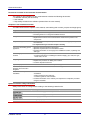
1 General information
Purpose of this chapter
This chapter shows you how to identify your combi steamer and provides guidance on using this manual.
Contents
This chapter includes the following topics:
Page
6
7
Identifying your combi steamer
About this installation manual
Installation manual
5
General information
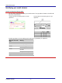
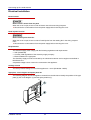
Identifying your combi steamer
Position and layout of the type plate
You can use the type plate to identify your combi steamer. The type plate is located on the left-hand
side of the combi steamer.
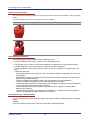
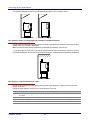
The type plate has the following layout on electric
appliances:
The type plate has the following layout on gas
appliances:
_
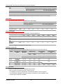
On both type plates, the code making up the trade name (1) identifies your appliance:
Elements of the trade
name
Meaning
Letters
1. letter
O = Eco (always present)
2. letter
E = Electric appliance
G = Gas appliance
3. letter
B = Appliance with steam
generator
S = Appliance with injection
Numerical values
xx.yy
Installation manual
Appliance size
6
General information
About this installation manual
Purpose
This installation manual provides answers to the following questions:
How do I set up the combi steamer?
How do I connect up the combi steamer?
How do I prepare the combi steamer for use?
The aim of this installation manual is to show you how to perform the following tasks:
Setting up the appliance.
Connecting the appliance to the electrical supply.
Connecting the appliance to the water supply.
Connecting the appliance to the gas supply.
Connecting the appliance to the flue gas installation.
Preparing the appliance for use.
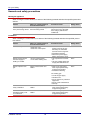
Who should read this manual
This installation manual is aimed at the following groups:
Staff
qualifications
Tasks
Personal protective
equipment required
Chapter to read
before task
Equipment mover
Conveying within the
Trained in the use of a
pallet truck and forklift
truck
For your Safety on
page 14
Personal protective
equipment as specified
by national regulations
for the given activity
Design and function
on page 9
establishment
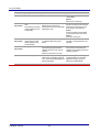
Service Engineer:
Setting up the applian-
Is an authorized customer
ce
Connecting the appliance
Preparing the appliance
for use
Instructing the user
service engineer.
Has relevant technical trai-
ning.
Is trained in the particular
appliance.
Conveying and
setting up the appliance on page 22
For your Safety on
page 14
Conveying and
setting up the appliance on page 22
Connecting up the
combi steamer on
page 33
Preparing for use on
page 56
Optional equipment
on page 60
Gas fitter:
Is a gas fitter authorized by
the gas supply company.
Has relevant professional
training.
Connecting the appli-
Electrician:
Is an authorized customer
service engineer.
Has relevant professional
training.
Is a qualified electrician.
Connecting the appli-
Installation manual
ance: gas
Personal protective
equipment as specified
by national regulations
for the given activity
Design and function
on page 9
For your Safety on
page 14
Connecting up the
combi steamer on
page 33
ance: electric
Personal protective
equipment as specified
by national regulations
for the given activity
Design and function
on page 9
For your Safety on
page 14
Connecting up the
combi steamer on
page 33
7
General information
Documents included in the Customer documentation
The customer documentation for the combi steamer includes the following documents:
Installation manual (this document)
User manual
Help facility included in the software (extracts from the user manual)
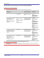
Chapters in the installation manual
The table below lists the chapters in this manual, summarizing their content, purpose and target group:
Step
Action
General information
Shows you how to identify your combi steamer.
Provides guidance on using this installation manual.
Design and function
Specifies the intended use of the combi steamer.
Explains the functions of the combi steamer and shows the position of its
components.
For your Safety
Describes the hazards posed by the combi steamer and appropriate preven-
tive measures.
It is important that you read this chapter carefully.
Conveying and setting up the
appliance
Specifies the basic appliance dimensions.
Specifies requirements for the installation location.
Provides information on conveying to the installation location, unpacking and
setting up.
Connecting up the combi
steamer
Lists necessary approvals.
Provides information on installing the electrical supply, gas, water, flue gas,
waste water, air vent
Preparing for use
Explains the procedure for preparing the appliance for use.
Explains the procedure for taking out of service.
Contains disposal instructions.
Optional equipment
Describes features of the various optional equipment.
Technical data, dimensional
drawings and connection
diagrams
Contains the technical data and connection diagrams.
Checklists and completion of
installation
Contains the checklists for
installation
Safety instructions and warnings
Customer guidance and instruction.
Contains information on the warranty and explains the completion procedure
using the checklists.
Symbols used for safety instructions
Safety instructions are categorized according to the following hazard levels:
Hazard level
Caution
Installation manual
Consequences
Likelihood
Death / serious injury (irreversible)
Immediate risk
Death / serious injury (irreversible)
Potential risk
Minor injury (reversible)
Potential risk
Damage to property
Potential risk
8
Design and function
2 Design and function
Purpose of this chapter
This chapter specifies the intended use of the combi steamer and explains its functions.
Contents
This chapter includes the following topics:
Page
10
11
Intended use of your combi steamer
Design and function of the combi steamer
Installation manual
9
Design and function
Intended use of your combi steamer
Intended use
The combi steamer must only be used for the purposes specified below:
The combi steamer is designed and built solely for professional cooking of a range of foodstuffs.
Steam, convection and superheated steam are used for this purpose.
The combi steamer is intended solely for commercial use.
Restrictions on use
The following restrictions on use must be observed:
The combi steamer must only be operated when all safety devices are fitted and in working order.
Dry powder or granulated material must not be heated in the combi steamer.
Easily inflammable objects with a flash point below 270 °C must not be heated in the combi steamer. These include items such as highly flammable oils, fats or cloths.
Food in sealed tins or jars must not be heated in the combi steamer.
Installation manual
10
Design and function
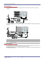
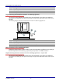
Design and function of the combi steamer
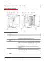
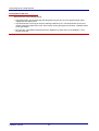
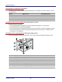
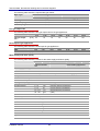
Table-top appliance construction
The following diagram shows a gas appliance and an electric appliance, representing all table-top
appliances:
Components of the table-top appliances and their function
The components of the table-top appliances have the following function
No.
Name
picture
Function
1
Air vent
Controls ventilation.
2
Gas flue pipe
Takes away flue gases:
1 gas flue pipe on appliances with injection
2 gas flue pipes on appliances with steam generator
3
Low-pressure failsafe
device
Prevents the low pressure in the oven e.g. during fully automatic cleaning
4
Multipurpose door handle
Has the following functions depending on its position:
Pointing vertically downwards: combi steamer closed, ready for cooking
Horizontal: combi steamer open, in on-latch position
20 degrees above horizontal: Combi steamer can be opened
Also has the following functions:
Additional function as far as on-latch position
In the on-latch position, door can be opened from inside oven in an
emergency
5
Oven door ("disappearing
door")
Seals the oven during cooking.
Special opening action allows it to slide back against the side of the
combi steamer to save space.
6
Hand shower
7
Installation manual
For rinsing out the cooker with water.
Continuous flow adjustment.
Switches the combi steamer on and off
11
Design and function
No.
Name
picture
Function
8
Touchscreen
Central control of the combi steamer:
Combi steamer operated by touching symbols on control-panel pages
Status displays
9
Oven compartment
Contains the food during cooking.
Has a different number of shelf levels depending on model.
10
rack
Used to hold GN containers or baking trays.
11
Appliance feet
Can be adjusted in height to allow the combi steamer to be placed horizontally.
12
Type plate
Used for identifying the combi steamer.
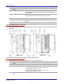
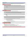
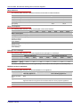
Floor-standing appliance construction
The following diagram shows a gas appliance and an electric appliance, representing all floor-standing
appliances:
Components of the floor-standing appliances and their function
The components of the table-top appliances have the following function:
No.
Name
picture
Function
1
Air vent
Controls ventilation
2
Number of gas flue pipes
Takes away flue gases.
1
2
2
3
3
Low-pressure failsafe
device
Installation manual
gas flue pipes: OGS 6.10, 6.20, 10.10, 10.20, 12.20
gas flue pipes: OGS 20.10, 20.20
gas flue pipes: OGB 6.10, 6.20, 10.10, 10.20, 12.20
gas flue pipes: OGB 20.10, 20.20
Prevents low pressure in the oven e.g. during fully automatic cleaning.
12
Design and function
No.
Name
picture
Function
4
Multipurpose door handle
Has the following functions depending on its position:
Pointing vertically downwards: combi steamer closed
Horizontal: combi steamer open but in on-latch position
20 degrees above horizontal: Combi steamer can be opened
Also has the following functions:
Additional function as far as on-latch position
In the on-latch position, door can be opened from inside oven in an
emergency
5
Oven door ("disappearing
door")
Seals the oven during cooking.
Special opening action allows it to slide back against the side of the combi
steamer to save space.
6
Hand shower
7
For rinsing out the cooker with water.
Continuous flow adjustment.
Switches the combi steamer on and off
8
Touchscreen
Central control of the combi steamer:
Combi steamer operated by touching symbols on control-panel pages
Status displays
9
Oven compartment
Contains the food during cooking.
Has a different number of shelf levels depending on model
10
Loading trolley
Used for loading food
11
Appliance feet
Can be adjusted in height to allow the combi steamer to be placed horizontally.
12
Preheat bridge
Used for safety purposes during preheating and cleaning.
13
Type plate
Used for identifying the combi steamer.
Installation manual
13
For your Safety
3 For your Safety
Purpose of this chapter
This chapter provides you with all the information you need in order to use the combi steamer safely
without putting yourself or others at risk.
This is a particularly important chapter that you should read through carefully.
Contents
This chapter includes the following topics:
Basic safety code
Warning signs on the combi steamer
Hazards and safety precautions
Safety devices
Requirements to be met by personnel, working positions
Installation manual
14
Page
15
16
18
19
21
For your Safety
Basic safety code
Object of this safety code
This safety code aims to ensure that all persons who use the combi steamer have a thorough knowledge of the hazards and safety precautions, and that they follow the safety instructions given in the
user manual and on the combi steamer. If you do not follow this safety code, you risk potentially fatal
injury and property damage.
Working with the user manual
Follow the instructions below:
Read in full the Safety chapter and chapters that relate to your work.
Always keep the user manual to hand for reference.
Pass on the user manual with the combi steamer if it changes ownership.
Working with the combi steamer
Follow the instructions below:
Only those persons who satisfy the requirements stipulated in this user manual are permitted to use
the combi steamer.
People (including children) who, because of their physical, sensory or intellectual capabilities, or
because of their lack of experience or knowledge, are incapable of using the appliance safely,
should not use this equipment without the supervision or guidance of a responsible person.
Only use the combi steamer for the specified use. Never, under any circumstances, use the combi
steamer for other purposes that may suggest themselves.
Take all the safety precautions specified in this user manual and on the combi steamer. In particular,
use the prescribed personal protective equipment.
Only stand in the working positions specified.
Do not make any changes to the combi steamer, e.g. removing parts or fitting un-approved parts. In
particular, you must not disable any safety devices.
More on this
Related topics
! Warning signs on the combi steamer.................................................................................................16
! Safety devices ....................................................................................................................................19
Installation manual
15
For your Safety
Warning signs on the combi steamer
Where are the hazard signs fitted?
The hazard signs are located in the following positions on the combi steamer:
Warning signs on the oven door
The following warning signs are fitted on the oven door above the door handle (2):
Warning sign
Description
Warning of hot liquids
Spillage of hot liquid foods can result in scalds if the upper shelves are loaded with
liquids or foods that produce liquid during cooking. Shelves above the level marked by
this warning sign (1.60 m) may not be seen by all users and should not, therefore, be
used for liquids or foods that produce liquid during cooking.
Warning of hot steam and vapor
There is a risk of scalding from hot steam and vapor escaping when the oven door is
opened.
Warning of corrosive cleaning agents injected into oven
If the oven door is opened during fully automatic cleaning, there is a risk of skin burns
from contact with cleaning agents being injected during the cleaning program.
Warning signs on the side cover of the combi steamer
The following warning signs are fitted on the side cover (1) of the combi steamer:
Warning sign
Description
Warning of electric shock
There is a risk of electric shock from live parts if the appliance cover is opened.
Installation manual
16
For your Safety
Warning signs on the loading trolley for floor-standing appliances
The following warning signs are fitted on the loading trolley of floor-standing appliances:
Warning sign
Description
Warning of hot liquids
Spillage of hot liquid foods can result in scalds if the upper shelves are loaded with
liquids or foods that produce liquid during cooking. Shelves above the level marked by
this warning sign (1.60 m) may not be seen by all users and should not, therefore, be
used for liquids or foods that produce liquid during cooking.
Installation manual
17
For your Safety
Hazards and safety precautions
Moving the appliance
When moving the combi steamer, be aware of the following hazards and take the specified preventive
actions:
Hazard
Where or in what situations
does the hazard arise?
Preventive action
Safety device
Risk of crushing from
heavy items being carried
When lifting up and setting down
the items being carried
Only allow suitably trained
personnel to move the appliance using a pallet truck or
forklift truck
None
installation
When installing the combi steamer, be aware of the following hazards and take the specified preventive actions:
Hazard
Where or in what situations
does the hazard arise?
Preventive action
Safety device
Risk from live parts
Under the cover
Under the control panel
Work on the electrical
Cover
Risk of electric shock if
the water supply is
leaking or cracked.
On the combi steamer
In the entire working area
Use a permanent connecti-
Risk of explosion from
gas
Where combi steamer is installed
Work on the gas system
system must only be performed by an authorized
customer service engineer.
Professional working.
Disconnect power supply
before removing the cover.
None
on.
Use only suitable pipes that
comply with DIN EN 61170.
None
must only be performed by
an approved gas fitter.
Professional working.
On smelling gas:
Cut off the gas supply.
Ventilate room.
Do not operate any electrical
equipment.
Do not create naked flames.
Get help.
Risk of suffocation from
faulty combustion
Where combi steamer is installed
Work on the gas system
Risk of suffocation from
insufficient supply of air
for combustion
Where combi steamer is installed
Work on the gas system
Installation manual
18
None
must only be performed by
an approved gas fitter.
must only be performed by
an approved gas fitter.
None
For your Safety
Safety devices
Meaning
The combi steamer has a number of safety devices to protect the user from hazards. It is absolutely
essential that all safety devices are fitted and in working order when operating the combi steamer
Position
The following diagrams show the location of the safety devices:
Functions
The following table enumerates all the safety devices on the combi steamer, explains their function
and describes the check procedure:
No.
Safety device
Function
Check
1
Cover can only be
removed using tool
Prevents live parts being tou-
Check that cover is fitted.
2
Control panel can only
be removed using a
tool
Prevents live parts being touched
accidentally.
Ensure that the control panel is
fitted.
3
Oven door
Protects the operator and outside
environment from hot steam.
Check regularly for scratches,
cracks, dents etc. and replace
door if any are found.
4
On-latch position of
oven door
Prevents scalding of user's face
and hands from escaping steam.
Check door positions at low
temperature as described in
Opening the oven door safely in
the user manual.
5
suction panel in oven
can only be removed
using tool
Prevents access to the moving
fan .
See Removing and fitting the
suction panel in the user manual
for further details.
6
Magnetic door switch:
Switches off the fan and heater
electrical door sensor in when the oven door is opened.
oven door
(no picture)
Installation manual
ched accidentally.
Prevents access to the moving
fan from the wiring compartment.
19
Check magnetic door switch at
low temperature:
Action
For your Safety
No.
Safety device
Function
Check
Opening the oven door fully
Press Start
Result
Motor must not start up.
7
(no picture)
In-Out function of oven
door;
Prevents anyone being
locked inside the oven
accidentally
8
Oven door in on-latch position:
Allows the oven door to be
pushed open from the inside after
shutting the door.
Check at low temperature:
put the oven door in the on-latch
position (see Opening the oven
door safely in user manual)
Action
From the outside, pull forcefully
on the top left of the oven door
Result
Oven door must open.
(no picture)
Automatic rinsing after
power failure in case
cleaning agent left in
combi steamer
Re-starts fully automatic cleaning
in a defined state after power
failure
This test is a software function.
The test is not performed by the
operator.
9
Spray-guard
Stops the cleaning agent being
injected during fully automatic
cleaning when the oven door is
opened
Prompt to close the oven door.
The operability of the magnetic
door switch is checked by the
software at the beginning of each
cleaning program
Preheat bridge
Prevents scalding from escaping
steam when the loading trolley is
not in the floor-standing appliance
during preheating.
See Inserting and removing the
preheat bridge (floor-standing
appliances only) in the user
manual for further details
(no picture)
10
Installation manual
20
For your Safety
Requirements to be met by personnel, working positions
Requirements to be met by personnel
Those people using the combi steamer must meet the following requirements:
Staff
qualifications
Tasks
Personal protective
equipment required
Chapter to read
before task
Equipment mover
Conveying within the
Trained in the use of a
pallet truck and forklift
truck
For your Safety on
page 14
Personal protective
equipment as specified
by national regulations
for the given activity
Design and function
on page 9
establishment
Service Engineer:
Setting up the applian-
Is an authorized customer
ce
Connecting the appliance
Preparing the appliance
for use
Instructing the user
service engineer.
Has relevant technical trai-
ning.
Is trained in the particular
appliance.
Conveying and
setting up the appliance on page 22
For your Safety on
page 14
Conveying and
setting up the appliance on page 22
Connecting up the
combi steamer on
page 33
Preparing for use on
page 56
Optional equipment
on page 60
Gas fitter:
Is a gas fitter authorized by
the gas supply company.
Has relevant professional
training.
Connecting the appli-
Electrician:
Is an authorized customer
service engineer.
Has relevant professional
training.
Is a qualified electrician.
Connecting the appli-
ance: gas
Personal protective
equipment as specified
by national regulations
for the given activity
Design and function
on page 9
For your Safety on
page 14
Connecting up the
combi steamer on
page 33
ance: electric
Personal protective
equipment as specified
by national regulations
for the given activity
Design and function
on page 9
For your Safety on
page 14
Connecting up the
combi steamer on
page 33
Working positions when installing and preparing the appliance for use
The working position for personnel installing and preparing the appliance for use is the entire appliance area.
Installation manual
21
Conveying and setting up the appliance
4 Conveying and setting up the appliance
Purpose of this chapter
This chapter specifies all the requirements for the installation location of the combi steamer, and explains the correct on-site procedure for conveying and unpacking the combi steamer, lifting it off the
pallet and setting it up.
Contents
This chapter includes the following topics:
Page
23
24
27
29
31
Dimensions, summary
Requirements for the installation location
Taking to the installation location
Unpacking
Setting up the appliance
Installation manual
22
Conveying and setting up the appliance
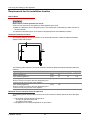
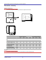
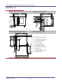
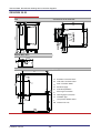
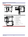
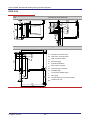
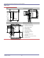
Dimensions, summary
Appliance dimensions
The following diagrams and tables summarize the appliance dimensions:
Table-top appliances
Floor-standing appliances
6.10
6.20
10.10
10.20
12.20
20.10
20.20
K = width with door open
90°
[mm]
1061
1302
1016
1302
1345
1016
1345
M = interior width of oven
[mm]
445
650
445
650
650
445
650
N = interior depth of oven
[mm]
640
640
640
840
840
640
840
O = interior height of oven
[mm]
492
535
760
760
956
1492
1492
P = width of hinge side
[mm]
45
45
45
45
60
60
60
Q = ledge height
[mm]
280
280
280
280
380
380
380
R = oven mouth depth
[mm]
33
33
33
33
33
33
33
Hand shower hose length
[mm]
1115
1115
1430
1430
1115
1640
1640
Material
The interior and exterior structure of the combi steamer is made of stainless steel.
Installation manual
23
Conveying and setting up the appliance
Requirements for the installation location
Risk of burns
Risk of burns if water splashes into hot fat
There is a risk of burns for the operator if water splashes into hot fat.
f Make sure that there are no deep-fat fryers or uncovered pans of fat within the radius of action of
the hand shower.
f Follow the instructions given in the section "Requirements for the installation location".
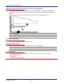
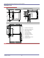
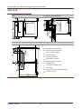
Horizontal minimum clearance
The following diagram shows the position of the horizontal minimum clearance distances between
adjacent walls and surfaces:
The following table shows the horizontal minimum clearance distances between adjacent walls and
surfaces:
Appliance type
a
b
c
Table-top appliances
[mm]
50
-
-
Floor-standing appliances
[mm]
75
50
100
Table-top appliances:
[mm]
130
-
-
[mm]
150
-
-
Minimum clearance needed to allow the disappearing door
to slide back fully along the side of the appliance.
Floor-standing appliances:
Minimum clearance needed to allow the disappearing door
to slide back fully along the side of the appliance.
Minimum vertical clearance above the appliance
The following points must be taken into account for the minimum vertical clearance above the appliance:
The minimum vertical clearance depends on:
the type of gas flue system and
the nature of the ceiling.
Gas appliances can reach temperatures of up to 400°C.
Installation manual
24
Conveying and setting up the appliance
The following table shows the values for the minimum vertical clearance above:
Appliance type
minimum vertical clearance above
Electric appliances
[mm]
500
Gas appliances
[mm]
1000
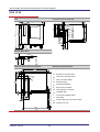
Minimum vertical clearance below the appliance
The following points must be taken into account for the minimum vertical clearance below the appliance:
Table-top appliances need to be installed at a height between 620 mm and 900 mm.
For gas appliances this area must not be blocked or obstructed.
The following diagram shows the passages required for the free flow of air:
Minimum distance from heat sources
The following diagram shows the minimum distances from heat sources:
The following table shows the values for the minimum distances from heat sources:
[mm]
a: Heat source (1)
500
b: Deep fat fryers, hot fat or oil (2)
Installation manual
Radius of action of the hand shower
25
Conveying and setting up the appliance
Minimum distance from flammable materials
There must be no flammable surfaces or materials (e.g. gases or liquids) in the vicinity of the combi
steamer.
Subfloor
The subfloor must have the following properties:
The subfloor must be flat and horizontal.
The subfloor must be able to bear the weight of the appliance including the maximum loading
weight. These figures are given in the chapters "Design and function" and "Technical data".
Environmental conditions
The following environmental conditions must be satisfied:
Health and safety at work regulations and local and national standards and directives must be observed.
The ambient temperature must lie between +4°C and +35°C.
The appliance must not be operated in potentially explosive atmospheres.
The appliance must be sheltered from the rain if operated outdoors.
Installation manual
26
Conveying and setting up the appliance
Taking to the installation location
Space required for conveying the appliance
The table below shows the required door size to allow the combi steamer to be brought to its intended
location:
Table-top appliances
Floor-standing appliances
6.10
6.20
10.10
10.20
12.20
20.10
20.20
Width
[mm]
1130
1410
1130
1410
1435
1150
1435
Height
[mm]
1002
1085
1270
1290
1596
2132
2138
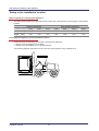
Conveying the appliance to the installation location
Please observe the following points when conveying the appliance:
Always move the appliance on a pallet.
Always move the appliance in an upright position.
The following diagram illustrates how to move the combi steamer using a forklift truck:
Installation manual
27
Conveying and setting up the appliance
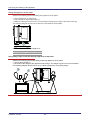
Taking the appliance off the pallet
Observe the following points when lifting the appliance off the pallet:
Use a forklift truck or pallet truck.
Place lengths of wood underneath (1).
Make sure that the forks are in the correct position (keeping to the right of the drain outlet (C))
The following diagram shows how to take the combi steamer off the pallet:
The following table shows the distance C:
C
[mm]
XX.10
XX.20
280
320
Using lifting straps to take the table-top appliance off the pallet
Observe the following points when lifting a table-top appliance off the pallet:
Use the lifting straps (1).
Be aware of the weight of the appliance when lifting it. The weight is given in the Technical Data.
The following diagram shows how to move a table-top appliance using lifting straps:
Installation manual
28
Conveying and setting up the appliance
Unpacking
Checking the tip indicator
Before unpacking the appliance, check the tip indicator on the packaging.
The following table shows the possible tip'n'tell indications:
Indication
Meaning
Action
Light arrow tip:
Unpack the appliance.
Appliance has been transported correctly.
Blue arrow tip:
Check the goods for damage.
Appliance has been turned over or transported on its side.
Note down on the accompanying paperwork
the fact that the tip indicator has actuated
and also any damage.
Unpacking
Unpack the appliance as follows:
Step
Action
1
Remove the outer packaging.
2
Remove all cardboard, packaging materials, documents, stickers, containers and loading trolley etc.
from inside the oven.
3
Remove the customer documentation. The customer documentation lies under the lid of the cardboard packaging box. It is located in position
(1) for table-top appliances.
(2) for floor-standing appliances.
4
Check the combi steamer for damage. If you suspect it has been damaged in transit notify your
dealer/carrier immediately. Please notify the manufacturer in writing within three days.
Caution
Never install or put into service a damaged appliance under any circumstances.
Installation manual
29
Conveying and setting up the appliance
Customer documentation
The following diagram shows where the customer documentation may be located:
Included with the appliance
The following table shows the parts included with the combi steamer:
Appliance
Included with the appliance
Basic table-top model
1x combi steamer
1x left-hand rack
1x right-hand rack
1x installation manual
1x user manual
Basic floor-standing model
1x combi steamer
1x loading trolley
1x installation manual
1x user manual
in addition for CONVOClean system
Installation manual
1x 10-liter canister, empty
30
Conveying and setting up the appliance
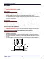
Setting up the appliance
All appliances
The following points must be observed when setting up the combi steamer:
Ensure the appliance cannot tip up or slide.
The ventilation slots on the appliance base (2) and the air vent and gas flue pipe on the appliance
top (1) must not be covered, blocked or obstructed.
The following diagram shows the air vent and gas flue pipe (1) and the ventilation slots (2):
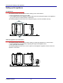
Table-top appliance on work surface
The following points must be observed when setting up a table-top appliance on a work surface:
Ensure the appliance is horizontal by adjusting the height of the appliance feet.
Use a spirit level for this task.
The following diagram shows how to use the spirit level and adjust the appliance feet to ensure the
appliance is horizontal:
Installation manual
31
Conveying and setting up the appliance
Table-top appliance on oven stand
The following points must be observed when setting up a table-top appliance on an oven stand:
Ensure the oven stand is horizontal by adjusting the height of the feet.
Use a spirit level for this task.
Hold the appliance feet in position using the locating pins on the oven rack.
The following diagram shows how to use the spirit level and adjust the feet to ensure the oven rack is
horizontal:
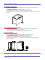
Table-top appliance on oven stand with wheels
Follow the instructions given for "Table-top appliance on oven stand", plus the following points:
Lock the wheels before connecting up the appliance.
Do not release the wheel locks until the appliance has been disconnected.
Floor-standing appliance
The following points must be observed when setting up a floor-standing appliance:
Ensure the appliance is horizontal by adjusting the height of the feet.
Use a spirit level for this task.
Make sure that the loading trolley is standing horizontally in the appliance.
The following diagram shows how to use the spirit level and adjust the appliance feet to ensure the
appliance is horizontal:
Installation manual
32
Connecting up the combi steamer
5 Connecting up the combi steamer
Purpose of this chapter
This chapter explains how to install your combi steamer.
Contents
This chapter includes the following topics:
Electrical installation
Energy optimization system
Water intake
Water drain
Gas installation to a fixed connection on OGS/OGB appliances
Gas installation for liquid gas bottles on OGS/OGB appliances
Flue gas removal system for OGS/OGB appliances
Safety precautions for gas appliances
Approvals
Installation manual
33
Page
34
36
37
40
44
47
51
54
55
Connecting up the combi steamer
Electrical installation
Electric shock
Risk of electric shock from live parts
When the cover is open, there is a risk of electric shock from touching live parts.
f Disconnect the combi steamer from the power supply before removing the cover.
Hand injuries from fan
Risk of hand injuries from fan
When the cover is open, there is a risk of hand injuries from the rotating fan in the wiring compartment.
f Disconnect the combi steamer from the power supply before removing the cover.
Requirements
The electrical supply must comply with the following regulations and requirements:
VDE (0100/0700)
Currently valid regulations of the electricity supply company
Electrical data on the type plate
The electricity supply must be connected by an authorized customer service engineer as defined in
DIN EN 50110-1.
A separate voltage source must not be connected to the appliance.
Leakage current
The factory-tested leakage current of the appliance is < 5 mA (EN 60335-1:2002).
Type plate, circuit diagram and spare parts list
The following diagram shows the appliance viewed from the left side to identify the position of the type
plate (2), the circuit diagram (1) and the spare parts list (1):
Installation manual
34
Connecting up the combi steamer
Design of the electrical installation
The following table shows the design rules for the electrical installation:
Component
Description
Fuse
Fuse-protection and connection of the combi steamer must comply with local
regulations and national installation directives. If necessary, the combi steamer
must be incorporated in a potential equalization system.
Disconnection device
An all-pole disconnection device with a minimum contact separation of 3 mm must
be installed close to the appliance. The disconnection device is used to disconnect
the appliance from the electrical supply for cleaning, repair and installation work.
Power cord
The power cord must be oil-resistant, sheathed and flexible. It must comply with
code designation 60245 IEC 57 (rubber insulated cord with polychloroprene
sheathing H05RN-F, H07RN-F)
Main terminal block
The main terminal block is located behind the left-hand removable side wall.
Cable gland
The cable gland serves as a strain relief mechanism and must be tightened firmly.
A specific phase angle is not required
Electrical supply
There is no need to connect the supply for a specific direction of rotation.
Carrying out the electrical installation
Follow the steps below to connect your combi steamer to the electrical supply:
Step
Action
1
Compare the ratings on the type plate with the building's power supply and circuit diagram.
2
Check all screw and clamp connections on the appliance. There is a risk of connections loosening
during transport.
3
Connect the appliance to the potential equalization system.
4
Connect the appliance by the mains cord to the disconnection device.
5
Connect the disconnection device to the ground fault circuit interrupter.
6
Make sure that the cable gland is tightened firmly because it also acts as a cable strain relief.
7
Remove all protective films from inside and outside the appliance.
Installation manual
35
Connecting up the combi steamer
Energy optimization system
Electric shock
Risk of electric shock from live parts
When the cover is open, there is a risk of electric shock from touching live parts.
f Disconnect the combi steamer from the power supply before removing the cover.
Hand injuries from fan
Risk of hand injuries from fan
When the cover is open, there is a risk of hand injuries from the rotating fan in the wiring compartment.
f Disconnect the combi steamer from the power supply before removing the cover.
Energy optimization system and combi steamer
You can connect the combi steamer to an energy optimization system (e.g. SICOTRONIC).
Please note the following points:
The minimum ON period is 8 minutes.
The maximum OFF period is 30 seconds.
The system may prolong pre-heat and cooking times.
Terminals for connecting to an energy optimization system
The combi steamer is connected to an energy optimization system via isolated contacts.
The terminals (B) and (C) of the main terminal block are isolated contacts. The main terminal block is
located behind the left-hand removable side wall.
Interpreting the signal:
If the appliance is switched on, the signal contact is closed.
If the connection to the energy optimization system is broken, the appliance switches into power-save mode (no heat output).
Installing an energy optimization system
Follow the steps below to connect your combi steamer to an energy optimization system:
Step
Action
1
Refer to the circuit diagram.
2
Remove the wire connection between the terminals (B) and (C) on the main terminal block.
3
Connect the terminals (B) and (C) of the main terminal block to the energy optimization system.
Installation manual
36
Connecting up the combi steamer
Water intake
Requirements
Observe the local and national regulations.
Water quality and water hardness
Compare the water quality and water hardness of the in-house supply with the values specified in the
"Water quality" and "Water hardness" tables in the "Technical Data" section . If the specified conditions are not satisfied, you must install suitable water filters and water treatment equipment.
Water filters and water treatment equipment
The following table lists the water filters and water treatment equipment that may be needed:
Component
Description
sediment filter
0.08 mm
A 0.08 mm sediment filter must be installed if the water has a high level of impurity.
Activated carbon
filter
If the redox potential of the water exceeds 300 mV and if the chlorine concentration (Cl2) >
0.1 mg/l then an activated carbon filter must be installed.
Hydrogen ion
exchanger
If the water hardness exceeds the permitted level, a hydrogen ion exchanger must be
installed. The hydrogen ion exchanger only needs to handle the water consumption for
moisture removal and steam generation.
The following table shows the flow rate required for the hydrogen ion exchanger:
Table-top appliances
Floor-standing appliances
6.10
6.20
10.10
10.20
12.20
20.10
20.20
OEB/OGB
[l/min]
0,2
0,4
0,4
0,6
0,7
0,7
1,0
OES/OGS
[l/min]
0,15
0,2
0,2
0,2
0,3
0,5
0,5
Water consumption
Note that the water consumption may increase significantly if the moisture removal option is used
frequently.
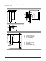
Design of the water installation
The following table shows the sequence of filters and water treatment equipment in the flow direction:
Symbol
Meaning
Z
Water supply line
X
Sediment filter 0.08 mm
W
Activated carbon filter
V
Hydrogen ion exchanger
Y
Cut-off tap with protective filter
Implementation of the water installation
The combi steamer is designed to be permanently connected to the customer's water supply. If it is
planned to use a flexible connecting pipe to supply water to the combi steamer, an EN 61177 compliant connecting pipe with a diameter of 3/8" min. must be used.
Installation manual
37
Connecting up the combi steamer
Installation diagram
The following diagram shows the connection diagram for water installations without a hydrogen ion
exchanger:
The following diagram shows the connection diagram for water installations containing a hydrogen ion
exchanger:
Item
Meaning
A
Soft water connection
B
Cold water connection
Appliance connection
Connect the appliance to a cold water supply, which must be of drinking water quality. Warm water up
to a temperature of 40°C can be supplied to the soft water connection.
The appliance water connection is located underneath the combi steamer (connection diagram: point A
and B). Fit protective filters.
Installation manual
38
Connecting up the combi steamer
Installing the water supply
Follow the steps below to provide the water supply to your combi steamer:
Step
Action
1
Find out the water quality and water hardness from your local water supply company.
2
Flush through the customer's water supply pipe.
3
Install the required water filters and water treatment equipment (X, W, V).
4
Fit a separate cut-off tap (Y) with protective filter for each appliance.
5
Connect the appliance to the pressure hose as shown in the connection diagram.
6
Inform the user of the service intervals for the filters and water treatment equipment.
7
Flush out the filter system.
Further information
The following sources provide information on the water supply for your combi steamer:
Drinking water installation data sheet
Water circuit diagram behind the motor cover
DIN 1988
DIN EN 61770
Installation manual
39
Connecting up the combi steamer
Water drain
Requirements
Observe the local and national regulations.
Safety overflow
The safety overflow is located on the underside of the combi steamer and is completely open to avoid
any backwater build-up.
The safety overflow prevents waste water from getting into the oven, for instance when the drain is
blocked or partially obstructed or if there is a rush of water during automatic cleaning.
In these circumstances, the waste water escapes via the open safety overflow under the appliance.
It is therefore recommended to connect the overflow to an open funnel waste trap for appliances with
an automatic cleaning system.
Drain connection
The following points must be observed when connecting the drain outlet:
The drain outlet is located underneath the combi steamer (connection diagram: point C).
The drain pipe must be at least DN 50 in size and must not contain any reduction in cross-section.
The drain pipe must have a minimum slope of 5 % (3°).
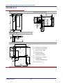
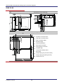
Drain connection for table-top appliances
A rigid pipe must be used to connect the drain outlet from table-top appliances to the drain system,
either via an open drain connection (e.g. funnel waste trap) or via a fixed connection.
Diagram showing the connection of a table-top appliance to a funnel waste trap
Caution
The funnel waste trap must not be installed under the combi steamer. Fit the funnel waste trap beside
or behind the combi steamer.
The minimum internal diameter of the drain pipe is 46 mm (DN 50). If more than one appliance is
connected to one drain pipe, this pipe must be large enough to allow the waste water to flow out unchecked.
The following diagram shows the drain connection to a funnel waste trap for table-top appliances:
Installation manual
40
Connecting up the combi steamer
Item
Meaning
1
Slope 5% (3°)
2
Waste pipe DN 50 (minimum internal diameter = 46 mm)
3
Drain pipe DN 50 (minimum internal diameter = 46 mm)
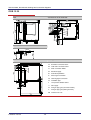
Diagram showing the fixed drain connection of a table-top appliance
The minimum internal diameter of the drain pipe is 46 mm (DN 50). If more than one appliance is
connected to one drain pipe, this pipe must be large enough to allow the waste water to flow out unchecked.
The following diagram shows the fixed drain connection for table-top appliances:
Item
Meaning
1
Slope 5% (3°)
2
Waste pipe DN 50 (minimum internal diameter = 46 mm)
3
Drain pipe DN 50 (minimum internal diameter = 46 mm)
Drain connection for floor-standing appliances
A rigid pipe must be used to connect the drain outlet from floor-standing appliances to the drain system, via an open drain connection (e.g. open tank), an open drain or a fixed connection.
Diagram showing the drain connection of a floor-standing appliance to an open tank
The minimum internal diameter of the drain pipe is 46 mm (DN 50). If more than one appliance is
connected to one drain pipe, this pipe must be large enough to allow the waste water to flow out unchecked.
Installation manual
41
Connecting up the combi steamer
The following diagram shows the drain connection to an open tank for floor-standing appliances:
Item
Meaning
1
Slope 5% (3°)
2
Waste pipe DN 50 (minimum internal diameter = 46 mm)
3
Tank with DN 50 drain pipe (minimum internal diameter = 46 mm)
Diagram showing the drain connection of a floor-standing appliance to an open drain
The minimum internal diameter of the drain pipe is 46 mm (DN 50). If more than one appliance is
connected to one drain pipe, this pipe must be large enough to allow the waste water to flow out unchecked.
The following diagram shows the drain connection to an open drain for floor-standing appliances:
Item
Meaning
1
Slope 5% (3°)
2
Waste pipe DN 50 (minimum internal diameter = 46 mm)
Installation manual
42
Connecting up the combi steamer
Diagram showing the fixed drain connection of a floor-standing appliance
The minimum internal diameter of the drain pipe is 46 mm (DN 50). If more than one appliance is
connected to one drain pipe, this pipe must be large enough to allow the waste water to flow out unchecked.
The following diagram shows the fixed drain connection for floor-standing appliances:
Item
Meaning
1
Slope 5% (3°)
2
Waste pipe DN 50 (minimum internal diameter = 46 mm)
Waste water temperature
The average waste water temperature equals 65°C.
Fitting the drain connection
Follow the steps below to provide the water drain for your combi steamer:
Step
Action
1
Connect the appliance as shown in the connection diagram.
Further information
The following sources provide information on the drain connection for your combi steamer:
DIN 1988 parts 2 and 4
DIN EN 1717
Local waste water regulations
Installation manual
43
Connecting up the combi steamer
Gas installation to a fixed connection on OGS/OGB appliances
Risk of explosion
Risk of explosion from escaping gas
Escaping gas can ignite and cause an explosion.
If you smell gas, follow the instructions below:
f Cut off the gas supply immediately.
f Ventilate the room thoroughly.
f Avoid creating a spark (e.g. by operating a switch, using a phone or touching electrical switching
elements).
f Tell the gas supplier or even the fire brigade (external telephone).
f Leave the building together with all other personnel.
Risk of suffocation
Risk of suffocation from lack of air suitable for breathing
Inadequate ventilation at the installation location can lead to suffocation.
Follow the instructions below accordingly:
f Only use the appliance in well ventilated rooms.
f Ensure that there is a sufficient supply of air for the level of combustion.
Class of gas appliance
There are two possible classes of gas appliance for the combi steamers:
Type
B23
Meaning
Usage
Open flues dependent on room air
OGS and OGB appliances are supplied as type B23 gas
appliances
with fan upstream of the burner and
without draught diverter
B13
Open flues dependent on room air
with fan upstream of the burner and
with draught diverter
All appliances can be installed as type B13 appliances by
retrofitting a draught diverter (available as an accessory).
Gas installation procedures
The following points must be observed when installing the gas:
The gas installation must only be carried out by an approved contract installation company of the
relevant gas supplier.
The gas fitter must not work on those parts sealed by the manufacturer or its authorized agents.
The gas installation must be performed in accordance with local regulations.
The gas installation must be performed in accordance with the regulations of the gas supply company.
In Germany these are:
Technische Regeln Gasinstallation TRGI (Techncial regulations for gas installation)
Technische Regeln Flüssiggas TRF (Technical regulations for liquid gas)
DWGW Arbeitsblatt G634 (DWGW worksheet)
DWGW Arbeitsblatt G21 (DWGW worksheet)
Installation manual
44
Connecting up the combi steamer
Appliance gas data
The combi steamer has been factory set to the requirements stated in the order. The type plate contains the figures for the gas settings.
Requirements
The supply flow pressure must be suitable for the appliance. If the measured supply flow pressure
differs from the figures given in the table below, the gas supply company must be notified. The appliance must not be put into service and the gas supply must be switched off.
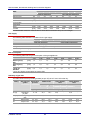
Summary of gas data
The table below lists the possible gas data (as per CE) at 15°C and 1013 mbar dry:
Family
Gas type and
symbol
Supply flow
pressure
Wobbe Index
lower
higher
WU
WO
Lower heating
value
Higher heating
value
HU
HO
HO
HU
3
[mbar]
[MJ/m ]
2H (E)
Natural gas
(H) G20
17 - 25
45,7
50,7
34,0
-
37,8
-
2L (LL)
Natural gas (L)
G25
18 - 30
37,4
41,5
29,3
-
32,5
-
3B
Butane G30*
25 - 57,5
80,6
87,3
116,1
45,7
125,8
49,5
3P
Propane G31
25 - 57,5
70,7
76,8
88,0
46,7
95,7
50,4
Flue gas values
Refer to the table below for the permitted flue gas values.
If the CO value is exceeded or the CO2 values not met,
the appliance must be re-adjusted by an authorized customer service engineer.
only operate the appliance during this period for maintenance and installation work.
ensure there is sufficient ventilation.
The following table shows the required flue gas values:
Type of gas
CO2
CO
[%]
[ppm]
8,6 - 9,6
< 500
Propane liquid gas
10,0 - 11,0
< 500
Butane liquid gas
11,7 - 12,7
< 500
Natural gas
Design of the gas installation
The following table shows the construction of the gas installation:
Component
Description
Fixed connection
The appliance is designed to be permanently connected to the customer's gas
supply. Position of the gas supply: point J in the connection diagram.
Gas cut-off tap
A gas cut-off tap must be fitted close to the appliance. The gas cut-off tap must not
be located within the safety clearance distances.
Gas wall outlet
A gas wall outlet can be used.
Pressure reducer
A pressure reducer must be fitted if the supply flow pressure is too high.
Installation manual
45
Connecting up the combi steamer
Component
Description
All connection components
All connection components provided by the customer must be tested in accordance
with local and national regulations.
Flexible gas pipe
Flexible gas pipes can be installed. If flexible pipes are used, they must be stainless
steel pipes approved under local and national regulations. The supply pipe must
have a minimum size of 3/4".
Installing the gas supply
Follow the steps below to provide the gas supply for your combi steamer:
Step
Action
1
Measure the supply flow pressure.
2
Compare the type of gas, the gas pressure and the rating for the gas supply connection with the
data given on the appliance type plate.
3
Fit a pressure reducer if the supply flow pressure is too high.
4
Fit the gas cut-off tap.
5
Connect the gas supply.
6
Check that all connections inside and outside the appliance are sealed (e.g. using gas detector or
leak locator spray).
Caution
Do not spray leak locator spray on the flame-monitor electrical leads.
7
Inform the user that the gas components must be serviced annually.
8
Check the flue gas values:
Carry out a flue gas analysis.
Check that the analysis values lie within the permitted flue gas values given in the table above.
Record the measurements in the appliance.
Installation manual
46
Connecting up the combi steamer
Gas installation for liquid gas bottles on OGS/OGB appliances
Risk of explosion
Risk of explosion from escaping gas
Escaping gas can ignite and cause an explosion.
If you smell gas, follow the instructions below:
f Cut off the gas supply immediately.
f Ventilate the room thoroughly.
f Avoid creating a spark (e.g. by operating a switch, using a phone or touching electrical switching
elements).
f Tell the gas supplier or even the fire brigade (external telephone).
f Leave the building together with all other personnel.
Risk of explosion
Risk of explosion from excess pressure
Fitting liquid gas bottles incorrectly can result in an explosion because of excess pressure.
Follow the fitting instructions below:
f Always install liquid gas bottles in an upright and stable position.
f Never use liquid gas bottles lying on their side.
f Prevent liquid gas bottles from getting hot.
f Never place liquid gas bottles in the warm air stream from the appliance.
Risk of suffocation
Risk of suffocation from lack of air suitable for breathing
Inadequate ventilation at the installation location can lead to suffocation.
Follow the instructions below accordingly:
f Only use the appliance in well ventilated rooms.
f Ensure that there is a sufficient supply of air for the level of combustion.
Class of gas appliance
There are two possible classes of gas appliance for the combi steamers:
Type
Meaning
Usage
B23
Open flues dependent on room air
OGS and OGB appliances are supplied as type B23 gas
appliances
with fan upstream of the burner and
without draught diverter
B13
Open flues dependent on room air
with fan upstream of the burner and
with draught diverter
Installation manual
All appliances can be installed as type B13 appliances by
retrofitting a draught diverter (available as an accessory).
47
Connecting up the combi steamer
Suitable liquid gas bottles
Only those liquid gas bottles suitable for gas take-off must be used for the installation using liquid gas
bottles.
The following table shows which liquid gas bottles are suitable:
Type of bottle
Suitability
suitable
not suitable
Gas installation procedures
The following points must be observed when installing the gas:
The gas installation must only be carried out by a qualified gas fitter.
The gas fitter must not work on those parts sealed by the manufacturer or its authorized agents.
The gas installation must be performed in accordance with local regulations.
The gas installation must be performed in accordance with the regulations of the gas supply company.
In Germany these are:
Feuerungsanlagenverordnung (FeuVo, FAV = Combustion equipment regulation) for each of the
federal states
Druckbehälterverordnung including the TRG (Pressurized container regulation plus technical regulations for pressurized gases)
Technische Regeln Gasinstallation TRGI (Techncial regulations for gas installation)
Technische Regeln Flüssiggas TRF (Technical regulations for liquid gas)
Unfallverhütungsvorschrift (UVV) "Verwendung von Flüssiggas" (Accident prevention regulations
"Use of liquid gas" (BGV D34/previously VGB 21))
Unfallverhütungsvorschrift (UVV) "Gase" (Accident prevention regulations "Gases" (BGV
B6/previously VGB 61))
Unfallverhütungsvorschrift (UVV) "Arbeiten an Gasleitungen" (Accident prevention regulations
"Working on gas pipelines" (BGV D2/previously VGB 50))
Arrangement using a bank of bottles
To avoid severe icing up of the liquid gas bottles, use a bank of bottles containing at least 2 liquid gas
bottles.
Caution
Protect the flexible gas lines from chemical, thermal and mechanical damage.
Installation manual
48
Connecting up the combi steamer
The following drawing and table show the construction of the gas installation using liquid gas bottles:
Item
Description
Requirement
1
Liquid gas bottle
suitable for gas take-off
2
HP flexible tube 0.40 m
Medium- or high-pressure pipe
to DIN 4815-1 or DIN3384
3
T connector
Standard design
4
Pressure regulator
Standards mark:
to DIN-DVGW or CE mark
Nominal flow rate Qn:
according to appliance size, see table
Pressure rating:
PN 16
Output pressure:
50 mbar
5
Burst pipe protection
Standard design
6
Flexible gas pipe to appliance
max. 2.00 m long
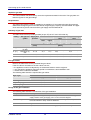
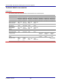
Selecting bottles for a bank of bottles
Caution
Open the valve on every bottle in the bank to achieve an even gas take-off from each.
Use the table below to select the correct number of liquid gas bottles for a bank:
Appliance size
OGS/OGB
Rating
Gas consumption
Liquid gas
[kW]
[kg/h]
11 kg each
33 kg each
6.10
12
0,9
2
1
6.20
20
1,5
2
1
10.10
30
1,5
2
1
10.20
35
2,7
-
2
12.20
40
3,1
-
2
20.10
40
3,1
-
2
20.20
70
5,4
-
3
Installation manual
49
Bank of bottles:
Number of liquid gas bottles
Connecting up the combi steamer
Flue gas values
Refer to the table below for the permitted flue gas values.
If the CO value is exceeded or the CO2 values not met,
the appliance must be re-adjusted by an authorized customer service engineer.
only operate the appliance during this period for maintenance and installation work.
ensure there is sufficient ventilation.
The following table shows the required flue gas values:
Type of gas
CO2
CO
%
ppm
Propane liquid gas
10,0 - 11,0
< 500
Butane liquid gas
11,7 - 12,7
< 500
Installing the gas supply
Follow the steps below to provide the gas supply for your combi steamer:
Step
Action
1
Measure the supply flow pressure.
2
Compare the type of gas, the gas pressure and the rating for the gas supply connection with the
data given on the appliance type plate.
3
Fit a pressure reducer if the supply flow pressure is too high.
4
Fit the gas cut-off tap.
5
Connect the gas supply.
6
Check that all connections inside and outside the appliance are sealed (e.g. using gas detector or
leak locator spray).
Caution
Do not spray leak locator spray on the flame-monitor electrical leads.
7
Inform the user that the gas components must be serviced annually.
8
Check the flue gas values:
Carry out a flue gas analysis.
Check that the analysis values lie within the permitted flue gas values given in the table above.
Record the measurements in the appliance.
Installation manual
50
Connecting up the combi steamer
Flue gas removal system for OGS/OGB appliances
Risk of explosion
Risk of explosion from escaping gas
Escaping gas can ignite and cause an explosion.
If you smell gas, follow the instructions below:
f Cut off the gas supply immediately.
f Ventilate the room thoroughly.
f Avoid creating a spark (e.g. by operating a switch, using a phone or touching electrical switching
elements).
f Tell the gas supplier or even the fire brigade (external telephone).
f Leave the building together with all other personnel.
Risk of suffocation
Risk of suffocation from lack of air suitable for breathing
Inadequate ventilation at the installation location can lead to suffocation.
Follow the instructions below accordingly:
f Only use the appliance in well ventilated rooms.
f Ensure that there is a sufficient supply of air for the level of combustion.
Combustion gases in gas appliances
Gas appliances produce combustion gases that must be vented to the outside air via a suitable flue
gas removal system.
Appliances must be installed in a room having adequate ventilation to prevent noxious combustion
gases reaching harmful concentration levels in the room.
Flue gas temperature
The temperature of the undiluted flue gas can reach 400°C.
Follow fire safety regulations.
Gas appliance under an extractor hood
The combi steamer can be installed under a fume extractor hood.
Make sure that a safety device is fitted that guarantees the following requirement:
The gas supply to the burner must only be allowed to flow when the extraction system is running.
Installation manual
51
Connecting up the combi steamer
The following diagram shows the combi steamer beneath the fume extractor hood:
Gas appliance under a ceiling fitted with ventilation equipment (option)
Combi steamers fitted with a draught diverter (type B13 gas appliance, option) can be fitted under a
ceiling containing ventilation equipment.
Make sure that a safety device is fitted that guarantees the following requirement:
The gas supply to the burner must only be allowed to flow when the extraction system is running.
The following diagram shows the combi steamer beneath a ceiling fitted with ventilation equipment:
Gas appliance connected directly to a flue
Combi steamers fitted with a draught diverter (type B13 gas appliance, option) can be connected
directly to the flue.
Follow the steps below to connect your combi steamer to the flue:
Step
Action
1
Use an approved registered chimney sweep to clean the flue system. Ensure you obtain a record of
this work.
2
Secure the appliance mechanically to prevent movement.
3
The gas flue pipes must be sealed and fitted in accordance with local and national regulations.
4
Inform the user that the flue system must be cleaned regularly.
Installation manual
52
Connecting up the combi steamer
Instructions for the user
Advise the user of the following points:
The gas flue pipe, its seal (rear left) and flue gases may be very hot. Flue gases and hot sheet
metal parts can cause burns.
The hand shower must only be used for cleaning inside the oven. The hand shower must not be
used to clean the outside of the case. Do not spray it onto gas supply connections, ventilation holes
or flue gas outlets.
Do not fit any combustible materials above the appliance or place them on the appliance. They
present a fire risk.
Installation manual
53
Connecting up the combi steamer
Safety precautions for gas appliances
Risk of explosion
Risk of explosion from escaping gas
Escaping gas can ignite and cause an explosion.
If you smell gas, follow the instructions below:
f Cut off the gas supply immediately.
f Ventilate the room thoroughly.
f Avoid creating a spark (e.g. by operating a switch, using a phone or touching electrical switching
elements).
f Tell the gas supplier or even the fire brigade (external telephone).
f Leave the building together with all other personnel.
Risk of suffocation
Risk of suffocation from lack of air suitable for breathing
Inadequate ventilation at the installation location can lead to suffocation.
Follow the instructions below accordingly:
f Only use the appliance in well ventilated rooms.
f Ensure that there is a sufficient supply of air for the level of combustion.
Combustion air supply for gas appliances
Ensure there is an adequate supply of combustion air.
Please note the following points:
The amount of combustion air required depends on the rated gas consumption.
In rooms in which the total heat output rating of all gas appliances is less than 50 kW, it is permitted
to rely on fresh air coming through gaps or windows to supply the combustion air.
Technical regulations
In Germany the following technical regulations must be observed:
Technische Regeln Flüssiggas TRF (Technical regulations for liquid gas)
DWGW Arbeitsblatt G600 (DWGW worksheet)
DWGW Arbeitsblatt G634 (DWGW worksheet)
VBG 21
Accident prevention regulation "Use of liquid gas"
VDI Directive 2052: Kitchen air conditioning and ventilation systems
Installation manual
54
Connecting up the combi steamer
Approvals
Notification of the installation
Notify the following bodies (where necessary) of the installation that has been made:
Gas supply company
Building inspection office
Registered chimney sweep
Industrial inspectorate
Installing the utility services
All work on customer facilities (electric/gas/water/waste water) must only be carried out by the relevant
utility company or by a registered installation company.
Statutory regulations
The relevant statutory regulations and building regulations must be observed.
Installation manual
55
Preparing for use
6 Preparing for use
Purpose of this chapter
This chapter explains how to prepare your combi steamer for use.
Contents
This chapter includes the following topics:
Page
57
59
Procedure for preparing the appliance for use
Taking out of service and disposal
Installation manual
56
Preparing for use
Procedure for preparing the appliance for use
Prior to putting the appliance into use
Before putting the appliance into use
Run through the checklists and safety instructions in the user manual and installation manual.
Read the chapter on setting up (Setting up the appliance on page 33) and connection (Connecting
up the combi steamer on page 33).
Never install or put into service a damaged appliance under any circumstances.
Preparing for use
To prepare the combi steamer for use, follow the steps below:
Step
Action
1
Ensure that the ambient temperature is higher than +4°C.
2
Reset the safety temperature limiter if necessary.
3
Open the water tap(s).
4
OGS/OGB:
Start the room ventilation system running.
Open the gas tap.
5
Check that the following are seated properly and in the correct position:
suction panel
racks
Loading trolley
6
Switch on the combi steamer at the main power switch.
7
Set the following:
date
time
language
Refer to the user manual for instructions on this.
8
Select the Superheated steam cooking program:
Set 150°C and 10 minutes. Refer to the user manual for instructions on this.
9
Check that the interior oven light is working.
10
Check ignition for the following gas burners:
OGS: burner for oven heater
OGB: burner for over heater and burner for steam generator
11
OGS/OGB:
Make sure the appliance is running within the specified flue gas levels (Gas installation to a fixed
connection on OGS/OGB appliances on page 44).
12
OES and OGS:
Run the appliance in Steam mode.
Use the pressure regulator to adjust the water supply reading for the steam generator to the
pressures in the table below:
13
OES and OGS
Water pressure
6.10, 6.20, 10.10, 10.20, 12.20
100 kPa (1.0 bar)
20.10 and 20.20
180 kPa (1.8 bar)
Appliance with automatic cleaning:
Start automatic cleaning.
Check the supply of CONVOClean and CONVOCare.
Installation manual
57
Preparing for use
Customer guidance and instruction.
Instruct the user in all safety-related functions and devices. Instruct the user in how to operate the
appliance.
Installation manual
58
Preparing for use
Taking out of service and disposal
Taking out of service
Requirements:
The appliance must be disconnected from the electrical supply
The gas supply must be cut off
The water supply must be cut off
To take your combi steamer out of service, perform the installation steps in the reverse order.
The following tasks must be performed correctly:
Disconnecting the water supply from the appliance
Removing the waste water connection from the appliance
Disconnecting or isolating the electrical supply.
Removing the door catch
plus for OGS/OGB appliances:
Disconnecting the gas supply from the appliance
Disconnecting the gas flue system if applicable
Disposal
Contact the manufacturer for guidance on environmentally safe disposal of your combi steamer. The
manufacturer is certified to the ISO 14001 environmental management standard.
Installation manual
59
Optional equipment
7 Optional equipment
Purpose of this chapter
This chapter explains how to put the optional equipment of your combi steamer into service.
Contents
This chapter includes the following topics:
CONVOClean automatic interior oven cleaning system
Ship model
Grill version
Stacking kit
Communications interface
Extractor hood/condensation hood
Installation manual
60
Page
61
64
65
67
68
69
Optional equipment
CONVOClean automatic interior oven cleaning system
Cleaning agents coming into contact with food
Risk of cleaning agents coming into contact with food
If the CONVOClean and CONVOCare connections are swapped over, there is a health risk from
eating the cooked dishes.
f Make sure that CONVOClean and CONVOCare are connected correctly.
f Use only products approved by the manufacturer.
Requirements
Make sure that the following requirements have been met:
Soft water supply connected as specified in the "Water supply" section
Water pressure (flow pressure) > 300 kPa and < 600 kPa (> 3 bar and < 6 bar)
Drain connected as specified in the "Water drain" section
Water hardness > 5 dH and < 7 dH
Included with the appliance
The following table shows the parts included with the CONVOClean system:
No.
Name
1
Delivery tube for cleaner suction nozzle (tube color: red)
2617594
1
2
Delivery tube for nozzle-detergent suction nozzle (tube color: transparent)
2617598
1
3
D10 wire clip
8009058
2
4
CONVOClean forte 10 ltr. (for manual cleaning and stubborn dirt)
3007017
1
5
CONVOClean new 10 ltr. (for all cleaning systems for light to heavy soiling)
3007015
1
6
CONVOCare concentrate 1 ltr. (nozzle detergent)
3007028
1
7
an empty CONVOCare canister
3007029
1
Cleaning agent and detergent
Only the specified materials must be used. This is the only way to ensure reliable and effective cleaning. You can obtain CONVOClean forte and CONVOCare from your distributor or ask the manufacturer.
The following table shows the approved cleaning agent and detergent:
Name
Product
Cleaning agents
CONVOClean forte
nozzle detergent
CONVOCare
Installation manual
61
Optional equipment
Cleaning agent and detergent consumption
The table below shows the cleaning agent and detergent consumption in liters per cleaning cycle for
cleaning level 3:
Material
Appliance size
Consumption (liters)
CONVOClean forte
6.10 / 6.20 / 10.10 / 10.20
0,90
CONVOCare
6.10 / 6.20 / 10.10 / 10.20
0,25
CONVOClean forte
12.20 / 20.10 / 20.20
1,40
CONVOCare
12.20 / 20.10 / 20.20
0,25
Installation location for the cleaning agent and detergent canisters
Install the canisters as follows:
The canisters should be located for easy access beside the appliance on a flat surface.
Check the fluid level in the canisters regularly.
The canisters must not be positioned above the level of the surface on which the appliance stands.
The level of the surface on which the canisters stand must not lie more than 1 m below the tube
connections on the appliance.
Arrangement of the cleaning-agent and detergent supply system:
The following diagram shows the arangement of the cleaning-agent and detergent supply system:
Label
Name
1
CONVOCare nozzle detergent canister
2
Delivery tube for nozzle-detergent suction nozzle (tube color: transparent)
3
D10 wire clip
4
Delivery tube for cleaner suction nozzle (tube color: red)
5
CONVOClean forte cleaning agent canister
F
Appliance connector for nozzle detergent supply
G
Appliance connector for cleaning agent supply
Installation manual
62
Optional equipment
Mixing the CONVOCare solution
To avoid excessive foaming, follow the procedure below when mixing the CONVOCare concentrate
with water:
Step
Action
1
Have available:
an empty CONVOCare canister
CONVOCare concentrate
a sufficient amount of soft water
2
Connect the cold water supply to the hand shower.
3
Read the label on the CONVOCare concentrate canister for the mixing instructions.
4
First add the water to the empty canister.
5
Add the correct amount of CONVOCare concentrate to the water.
6
Mix the two together thoroughly by stirring.
Connecting the CONVOClean system
Follow the steps below to connect the CONVOClean system:
Step
Action
1
Mix the supplied CONVOCare concentrate with soft water in the empty CONVOCare canister.
Follow the instructions above for mixing the CONVOCare solution.
2
Plug the red extractor tube (4) for the cleaning agent onto the connector nipple of the front tube fitting
(G) and hold in place with the wire clip (3).
3
Plug the transparent extractor tube (2) for the detergent onto the connector nipple of the front tube
fitting (F) and hold in place with the wire clip (3).
4
Plug the red suction nozzle into the canister of CONVOClean forte (5). There must be no kinks in the
tube and the vent hole in the canister must be open and unblocked.
5
Plug the transparent suction nozzle into the canister of CONVOCare (1). There must be no kinks in
the tube and the vent hole in the canister must be open and unblocked.
6
Inform the user that the appliance must not be opened during cleaning. There is a risk of chemical
burns to the eyes.
Optional customization
As an option, automatic cleaning can be customized to suit the user's requirements by a trained service engineer with access to the Service level in the user interface.
Installation manual
63
Optional equipment
Ship model
Function
On board ship, the combi steamer is fixed to the floor by screws.
Fixing by flanged feet
Caution
If the appliance is fixed by means other than the flanged feet (e.g. by welding), the appliance must be
leveled before fixing.
The following diagram shows how you can fix floor-standing appliances or table-top appliances using
the flanged feet:
Fixing to the ship oven-stand
To fix the combi steamer to a ship oven-stand, follow the steps below:
Step
Action
1
Using a spirit level, ensure the ship oven-stand is horizontal by adjusting the height of the feet.
2
Align the fixing bracket with the oven stand via the slotted holes and screw it to the oven stand.
3
Fasten the fixing bracket to the floor.
4
Remove the appliance feet with flange plate from the combi steamer.
5
Fit the M8 threaded feet supplied to the base.
6
Place the combi steamer on the oven stand and position the feet over the holes in the oven stand.
7
Using a spirit level, ensure the appliance is horizontal by adjusting the height of the feet.
8
Screw the square tubing of the oven stand to the appliance feet from below using the screws, plain
washers and spring washers supplied.
Installation manual
64
Optional equipment
Grill version
Design and function
The grill version has a separate fat run-off. Intermediate plates prevent seasoning being washed off by
drops of liquid from above.
A fat collecting tray collects any liquid dripping off the grilled food, which then flows out through a drain
hole and tube directly into an external fat collecting container. The fat collecting container contains
water up to the level of the tube end. This ensures the closed system inside the combi steamer is
maintained.
If the combi steamer is not being used for grilling, the fat collecting tray and the intermediate plates
should be removed from the appliance and the fat drain hole sealed with a screw plug.
The following diagram shows the design of the fat drain system in the grill version:
Included with the appliance
The following table shows the parts included with the grill version:
No.
Name
Part no.
Qty per appliance
6.10
10.10
1
2
2
3
1
Intermediate plate for chicken grill
2
Chicken grill mesh
3
Fat collecting tray
1
1
4
Pipe bend
1
1
5
Tube with screw connector. Use longer or shorter tube as required
(tube + hose clip + tube clamp)
1
1
6
Screw plug for fat drain hole
1
1
On
request
Connecting the grill version to fat collecting container when container placed beneath the combi
steamer
To connect the fat collecting container under the appliance, follow the steps below:
Step
Action
1
Place the fat collecting container (e.g. metal pail approx .10 - 15 liters) in a stable position under the
appliance.
2
Screw the tube connector onto the threaded outlet of the fat drain under the appliance base.
3
Feed the tube down into the fat collecting container, avoiding any kinks.
Installation manual
65
Optional equipment
Connecting the grill version to fat collecting container when container placed beside the combi
steamer
To connect the fat collecting container beside the appliance, follow the steps below:
Step
Action
1
Place the fat collecting container (e.g. metal pail approx .10 - 15 liters) in a stable position beside the
appliance.
2
Screw the pipe bend onto the threaded outlet of the fat drain under the appliance base.
3
Screw the tube connector onto the pipe bend.
4
Feed the tube down into the fat collecting container, avoiding any kinks.
Preparing for use
To set up the fat collecting container for use, follow the steps below:
Step
Action
1
Fill the fat collecting container with about 5 cm of water so that the tube mouth lies under the surface
of the water. Make sure that the fat can drain freely into the fat collecting container.
2
Unscrew the plug from the drain outlet in the appliance base.
3
Slide the fat collecting tray into the appliance (do not slide into the rack but insert directly on the oven
floor).
Caution:
The drain from the fat collecting tray must lie over the center of the fat drain outlet in the oven floor.
4
Insert the intermediate plates.
5
After preheating, place the chicken grills (with chicken on top) in the oven.
6
Inform the user that there must always be water in the fat collecting container (above the level of the
tube mouth). Otherwise the closed system inside the oven is unable to work.
7
Inform the user that the fat collecting tray must be removed from the appliance and the screw plug
inserted in the fat drain outlet before
every automatic cleaning cycle.
every automatic steam generator rinse.
any cleaning operation using the hand shower.
Applications that are not permitted
When the plug in the fat drain outlet is unscrewed, it is not permitted to operate the appliance as follows:
Without a fixed connection to the fat drain outlet
With the fluid running off into an open container beneath the appliance
Without an initial amount of fluid in the fat collecting container
The manufacturer accepts no liability for any damage caused by incorrect installation.
Installation manual
66
Optional equipment
Stacking kit
Function
The stacking kit can be used to place two combi steamers one above the other.
Permitted combinations
Caution
Never place a size 10.10 or 10.20 appliance on top.
You can only install electric appliances on electric appliances and gas appliances on gas appliances.
The following combinations are allowed:
6.10 on 6.10
6.10 on 10.10
6.20 on 6.20
6.20 on 10.20
Potential equalization
Incorporate the stacking kit in the potential equalization system.
Assembly and installation
Please refer to the "Service" manual for information on assembling the "Electric appliance" and "Gas
appliance" stacking kits.
Please refer to the separate instructions for information on installation.
Installation manual
67
Optional equipment
Communications interface
Serial interface
All combi steamers are fitted with an EIA-232 (RS-232) communications interface.
A special interface cable is required to connect a PC via the built-in EIA-232 (RS232) interface.
Function of the communications interface
The communications interface is used for networking a computer and combi steamer.
The CONVOHACCP software can be used for automatic logging and subsequent documentation of all
cooking processes.
In addition, the CONVOControl software can be used to edit recipes and transfer them to and from the
combi steamer.
Modules for the network connection
A separate communications module is required for connecting a combi steamer to a network. There
are two models.
The following table shows the two communications modules together with the interfaces:
Interfaces
Module A
Module B
EIA-232 (RS232) (Connected using standard
EIA-232 (RS232) (Connected using stan-
commercial 9-pin connector.)
EIA-485 (RS-485)
USB interface
dard commercial 9-pin connector.)
EIA-485 (RS-485)
USB interface
Ethernet/LAN
Requirements
Firmware version V4.12 and above and CONVOHACCP support the use of the USB and Ethernet
interfaces.
installation
Refer to the installation instructions for the communications modules for further details.
Installation manual
68
Optional equipment
Extractor hood/condensation hood
Recommended extractor hoods/condensation hoods
An extractor hood is not a strict stipulation for operating the combi steamer.
If you plan to fit an extractor hood, we recommend the CONVOTHERM Extractor hood (extractor
hood) or the CONVOTHERM Condensation hood without extractor pipe and with cold water supply
and water drain.
Requirements
The appliance must be placed in a stable position before mounting a hood on an appliance. This is
particularly relevant for combi steamers installed on an oven stand with wheels.
Ensure that there is a sufficient supply of air.
Local and national regulations relating to requirements of air conditioning equipment must be followed.
Grease filters
Fit grease filters in the overhanging hood section.
Grease filters must be removed at regular intervals and washed in the dishwasher. Observe manufacturer's data.
Operation
Always switch the hood on when the combi steamer is running. Otherwise condensation may collect in
the appliance.
Moving the appliance
Remove the extractor hood prior to moving.
Table-top appliances with oven stand must be screwed firmly onto the oven rack.
Technical data
The table below contains the technical specification for extractor hoods:
Appliance size
6.10
6.20
10.10
10.20
Part no. Extractor hood for OEB/OES electric appliances
3416801
3416821
3416801
3416821
Part no. Extractor hood for OGB gas appliances
3416871
3416872
3416873
3416881
Part no. Extractor hood for OGS gas appliances
3416860
3416874
3417015
3416875
Dimensions W x D x H [mm]
905 x 1160
x 414
1190 x
1385 x 414
905 x 1160
x 414
1190 x
1385 x 414
1/N/PE AC 230V 50/60 Hz
16A
IPX4
1450 m³/h with no extractor pipe connected
1390 m³/h at p= 8mmWS
1100 m³/h at p= 16mmWS
Stainless steel
Rated voltage
Fuse
Degree of protection*
Fan extraction rate for '=1.2 kg/m³
Fan extraction rate for '=1.2 kg/m³
Fan extraction rate for '=1.2 kg/m³
Material
*The IPX4 degree of protection of the extractor hood does not include the connection between the
power cord and earthed socket.
Installation manual
69
Technical data, dimensional drawings and connection diagrams
8 Technical data, dimensional drawings and connection diagrams
Purpose of this chapter
This chapter contains the technical data, dimensional drawings and connection diagrams for your
combi steamer.
Contents
This chapter includes the following topics:
Technical data
Dimensions, dimensional drawings and connection diagrams
Installation manual
70
Page
71
90
Technical data, dimensional drawings and connection diagrams
8.1 Technical data
Purpose of this chapter
This chapter contains the technical data for your combi steamer.
Contents
This chapter includes the following topics:
Page
72
76
80
84
89
Technical data for OEB
Technical data for OES
Technical data for OGS
Technical data for OGB
Technical data for accessories
Installation manual
71
Technical data, dimensional drawings and connection diagrams
Technical data for OEB
Dimensions and weights
The following table shows appliance dimensions and weights:
OEB
6.10
6.20
10.10
10.20
Table-top appliances
12.20
20.10
20.20
Floor-standing appliances
Width
including loading trolley
with packaging
[mm]
1130
1410
1130
1410
1435
1150
1435
without packaging
[mm]
932
1217
932
1217
1232
947
1232
Depth [mm]
including loading trolley
with packaging
[mm]
950
1175
950
1175
1200
1000
1200
without packaging
[mm]
805
1027
805
1027
1055
855
1055
Height [mm]
including loading trolley
with packaging
[mm]
1040
1105
1310
1330
1650
2185
2185
without packaging
[mm]
852
895
1120
1120
1416
1952
1952
Weight
including loading trolley
with packaging
[kg]
190
256
220
312
376
372
492
without packaging
[kg]
155
215
175
245
314
315
414
Weight with ConvoClean system
including loading trolley
with packaging
[kg]
210
276
240
332
396
392
512
without packaging
[kg]
163
223
183
253
322
323
422
Rear
[mm]
50
Right-hand side
[mm]
50
Left-hand side
[mm]
100
Above
[mm]
500 (for ventilation)
Safety clearances [mm]
Electrical installed load ratings
The following table shows the electrical installed load ratings:
OEB
6.10
6.20
10.10
10.20
Table-top appliances
12.20
20.10
20.20
Floor-standing appliances
3/N/PE ~ 400V 50/60Hz
Rated power consumption
[kW]
11,4
19,8
19,8
34,3
34,3
39,6
68,5
Convection power
[kW]
10,5
18,9
18,9
33,0
33,0
37,8
66,0
Steam power
[kW]
9,9
16,5
16,5
26,4
29,7
29,7
39,6
Motor power
[kW]
0,8
0,8
0,8
1,2
1,2
1,7
2,4
Rated current
[A]
15,3
26,3
26,3
47,6
47,6
52,4
95,0
[6]
0,627
0,252
0,252
0,113
0,113
0,125
-
max. permissible system
impedance Zsys
Fuse
recommended wire
cross-section*
Installation manual
[A]
2
[mm ]
16,0
35,0
35,0
50,0
50,0
63,0
100,0
5x 4
5x 6
5x 6
5x 16
5x 16
5x 16
5x 35
72
Technical data, dimensional drawings and connection diagrams
OEB
6.10
6.20
10.10
10.20
Table-top appliances
12.20
20.10
20.20
Floor-standing appliances
3/PE ~ 230V 50/60Hz
Rated power consumption
[kW]
11,7
20,1
20,1
Convection power
Steam power
34,6
34,6
40,1
69,1
[kW]
10,5
18,9
18,9
33,0
33,0
37,8
66,0
[kW]
9,9
16,5
16,5
26,4
29,7
29,7
39,6
Motor power
[kW]
0,8
0,8
0,8
1,5
1,5
2,2
3,0
Rated current
[A]
27,2
46,2
46,2
83,5
83,5
92,3
166,9
max. permissible system
impedance Zsys
[6]
0,239
0,151
0,151
-
-
-
-
Fuse
[A]
16,0
35,0
35,0
50,0
50,0
63,0
100,0
5x 16
5x 35
5x 35
5x 35
5x 95
2
[mm ]
5x 6
Rated power consumption
[kW]
11,7
20,1
20,1
34,6
34,6
40,1
69,1
Convection power
[kW]
10,5
18,9
18,9
33,0
33,0
37,8
66,0
Motor power
[kW]
1,1
1,1
1,1
1,5
1,5
2,2
3,0
Steam power
[kW]
9,9
16,5
16,5
26,4
29,7
29,7
39,6
Rated current
[A]
30,8
52,7
52,7
95,4
95,4
105,2
190,6
max. permissible system
impedance Zsys
[6]
0,239
0,151
0,151
-
-
-
-
recommended wire
cross-section*
5x 16
3/PE ~ 200V 50/60Hz
Fuse
16,0
35,0
35,0
50,0
50,0
63,0
100,0
[mm ]
5x 6
5x 16
5x 16
5x 35
5x 35
5x 35
x 95
latent
[kJ/h]
2100
3500
3500
6400
6900
6900
12200
sensible
[kJ/h]
2500
4500
4500
7800
7800
8900
15400
recommended wire
cross-section*
[A]
2
Heat output
*recommended conductor cross-section for wires laid uncovered in air up to 5 m in length.
*recommended conductor cross-section for wires laid uncovered in air up to 5 m in length.
Water supply and water quality
The following table shows the values for the water supply and water quality:
6.10
6.20
10.10
Table-top appliances
10.20
12.20
20.10
Floor-standing appliances
Water supply (cold only)
Shut-off valve
with non-return valve and dirt filter
Water intake
G 3/4'', permanent connection optional with min. 3/8" supply pipe
Flow pressure
without ConvoClean system
2 - 6 bar
with ConvoClean system
3 - 6 bar
Drinking water quality (install water treatment unit if necessary)
Overall hardness
Installation manual
20.20
5 - 15
°dH
(German degrees of hardness)
9 - 13
°fH
(French degrees of hardness)
73
Technical data, dimensional drawings and connection diagrams
6.10
6.20
10.10
10.20
12.20
Table-top appliances
°eH
(English degrees of hardness)
90 - 120
ppm
(USA)
6,5 - 8,5
Conductivity
10 - 200 μS/cm
Cl
-
SO4
20.20
Floor-standing appliances
6,3 - 8,8
pH
20.10
max. 100 mg/l
-
max. 400 mg/l
Fe
max. 0.1 mg/l
Mn
max. 0.05 mg/l
Cu
max. 0.05 mg/l
Cl2
max. 0.1 mg/l
Water drain
Type
DN 50, permanent connection or funnel waste trap
Water hardness
The following table shows the approved minimum and maximum water hardness:
min.
max.
°dH (German degrees of hardness)
5,0
18,0
°fH (French degrees of hardness)
9,0
33,0
°eH (English degrees of hardness)
6,3
23,0
ppm (USA)
90,0
320,0
Water consumption
The following table shows the water consumption of the combi steamer:
6.10
6.20
10.10
10.20
12.20
20.10
20.20
80-100
6
Water consumption
Total (guide value)
Max. consumption for
appliance without
automatic interior
oven cleaning
[l/h]
[l/min]
20-30
6
30-50
6
30-50
6
40-70
6
50-80
6
60-80
6
Max. consumption for
appliance with
automatic interior
oven cleaning
[l/min]
11
11
11
11
11
11
11
Hydrogen ion exchanger
The following table shows the flow rate required for the hydrogen ion exchanger:
Table-top appliances
Floor-standing appliances
OEB/OGB
[l/min]
6.10
0,2
6.20
0,4
10.10
0,4
10.20
0,6
12.20
0,7
20.10
0,7
20.20
1,0
OES/OGS
[l/min]
0,15
0,2
0,2
0,2
0,3
0,5
0,5
The water consumption may increase significantly if the moisture removal option is used frequently.
Installation manual
74
Technical data, dimensional drawings and connection diagrams
Steam generator
The following table shows the nominal output and capacity of the stream generator:
OEB
6.10
6.20
10.10
10.20
Table-top appliances
12.20
20.10
20.20
Floor-standing appliances
Rated output (guide
value)
[kg/h]
12,6
21,0
21,0
31,4
37,8
37,8
50,4
Contents
[liters]
6,5
9,0
9,0
12,5
12,5
12,5
17,0
Appliance technical standards
The following table shows the technical standards for the appliance:
6.10
6.20
10.10
Table-top appliances
10.20
12.20
20.10
20.20
Floor-standing appliances
Degree of protection
IPX5
Approval mark
TÜV, GS, DIN GOST TÜV, SVGW, WRAS, UL, NSF
Approval marks are only present on the device based on country-specific regulations.
Noise emission
measured
Installation manual
< 70 dBA
75
Technical data, dimensional drawings and connection diagrams
Technical data for OES
Dimensions and weights
The following table shows appliance dimensions and weights:
OES
6.10
6.20
10.10
10.20
Table-top appliances
12.20
20.10
20.20
Floor-standing appliances
Width
including loading trolley
with packaging
[mm]
1130
1410
1130
1410
1435
1150
1435
without packaging
[mm]
932
1217
932
1217
1232
947
1232
Depth
including loading trolley
with packaging
[mm]
950
1175
950
1175
1200
1000
1200
without packaging
[mm]
805
1027
805
1027
1055
855
1055
with packaging
[mm]
1040
1105
1310
1330
1650
2185
2185
without packaging
[mm]
852
895
1120
1120
1416
1952
1952
Height
including loading trolley
Weight
including loading trolley
with packaging
[kg]
176
246
206
280
362
362
482
without packaging
[kg]
136
196
165
225
288
295
395
Weight with ConvoClean system
including loading trolley
with packaging
[kg]
196
266
226
300
382
382
502
without packaging
[kg]
144
204
173
233
296
303
403
Rear
[mm]
50
Right-hand side
[mm]
50
Left-hand side
[mm]
100
Above
[mm]
500 (for ventilation)
Safety clearances
Electrical installed load ratings
The following table shows the electrical installed load ratings:
OES
6.10
6.20
10.10
10.20
Table-top appliances
12.20
20.10
20.20
Floor-standing appliances
3/N/PE ~ 400V 50/60Hz
Rated power consumption
[kW]
11,4
19,8
19,8
34,3
34,3
39,6
68,5
Convection power
[kW]
10,5
18,9
18,9
33,0
33,0
37,8
66,0
Motor power
[kW]
0,8
0,8
0,8
1,2
1,2
1,7
2,4
Rated current
[A]
15,3
26,3
26,3
47,6
47,6
52,4
95,0
max. permissible system
impedance Zsys
[6]
0,627
0,252
0,252
0,113
0,113
0,125
-
Fuse
[A]
recommended wire
cross-section*
16,0
35,0
35,0
50,0
50,0
63,0
100,0
2
[mm ]
5x 4
5x 6
5x 6
5x 16
5x 16
5x 16
5x 35
[kW]
11,7
20,1
20,1
34,6
34,6
40,1
69,1
3/PE ~ 230V 50/60Hz
Rated power consumption
Installation manual
76
Technical data, dimensional drawings and connection diagrams
OES
6.10
6.20
10.10
10.20
Table-top appliances
12.20
20.10
20.20
Floor-standing appliances
Convection power
[kW]
10,5
18,9
18,9
33,0
33,0
37,8
66,0
Motor power
[kW]
0,8
0,8
0,8
1,5
1,5
2,2
3,0
Rated current
[A]
27,2
46,2
46,2
83,5
83,5
92,3
166,9
max. permissible system
impedance Zsys
[6]
0,239
0,151
0,151
-
-
-
-
Fuse
16,0
16,0
35,0
50,0
50,0
63,0
100,0
[mm ]
2
5x 6
5x 16
5x 16
5x 35
5x 35
5x 35
5x 95
Rated power consumption
[kW]
11,7
20,1
20,1
34,6
34,6
40,1
69,1
Convection power
[kW]
10,5
18,9
18,9
33,0
33,0
37,8
66,0
Motor power
[kW]
1,1
1,1
1,1
1,5
1,5
2,2
3,0
Rated current
[A]
30,8
52,7
52,7
95,4
95,4
105,2
190,6
max. permissible system
impedance Zsys
[6]
0,239
0,151
0,151
-
-
-
-
recommended wire
cross-section*
[A]
3/PE ~ 200V 50/60Hz
Fuse
16,0
16,0
35,0
50,0
50,0
63,0
100,0
[mm ]
5x 6
5x 16
5x 16
5x 35
5x 35
5x 35
5x 95
latent
[kJ/h]
2100
3500
3500
6400
6900
6900
12200
sensible
[kJ/h]
2500
4500
4500
7800
7800
8900
15400
recommended wire
cross-section*
[A]
2
Heat output
*recommended conductor cross-section for wires laid uncovered in air up to 5 m in length.
Water supply and water quality
The following table shows the values for the water supply and water quality:
6.10
6.20
10.10
Table-top appliances
10.20
12.20
20.10
Floor-standing appliances
Water supply (cold only)
Shut-off valve
with non-return valve and dirt filter
Water intake
G 3/4'', permanent connection optional with min. 3/8" supply pipe
Flow pressure
without ConvoClean system
2 - 6 bar
with ConvoClean system
3 - 6 bar
Drinking water quality (install water treatment unit if necessary)
Overall hardness
5 - 15
°dH
(German degrees of hardness)
9 - 13
°fH
(French degrees of hardness)
6,3 - 8,8
°eH
(English degrees of hardness)
90 - 120
ppm
(USA)
pH
6,5 - 8,5
Conductivity
10 - 200 μS/cm
Cl
-
SO4
max. 100 mg/l
-
Fe
Installation manual
20.20
max. 400 mg/l
max. 0.1 mg/l
77
Technical data, dimensional drawings and connection diagrams
6.10
6.20
10.10
10.20
12.20
Table-top appliances
Mn
max. 0.05 mg/l
Cu
max. 0.05 mg/l
Cl2
max. 0.1 mg/l
20.10
20.20
Floor-standing appliances
Water drain
Type
DN 50, permanent connection or funnel waste trap
Water hardness
The following table shows the approved minimum and maximum water hardness:
min.
max.
°dH (German degrees of hardness)
5,0
7,0
°fH (French degrees of hardness)
9,0
13,0
°eH (English degrees of hardness)
6,3
8,8
ppm (USA)
90,0
125,0
Water consumption
The following table shows the water consumption of the combi steamer:
6.10
6.20
10.10
10.20
12.20
20.10
20.20
80-100
Water consumption
Total (guide value)
20-30
30-50
30-50
40-70
50-80
60-80
Max. consumption for
appliance without
automatic interior
oven cleaning
[l/min]
[l/h]
6
6
6
6
6
6
6
Max. consumption for
appliance with
automatic interior
oven cleaning
[l/min]
11
11
11
11
11
11
11
Hydrogen ion exchanger
The following table shows the flow rate required for the hydrogen ion exchanger:
Table-top appliances
Floor-standing appliances
6.10
6.20
10.10
10.20
12.20
20.10
20.20
OEB/OGB
[l/min]
0,2
0,4
0,4
0,6
0,7
0,7
1,0
OES/OGS
[l/min]
0,15
0,2
0,2
0,2
0,3
0,5
0,5
The water consumption may increase significantly if the moisture removal option is used frequently.
Installation manual
78
Technical data, dimensional drawings and connection diagrams
Appliance technical standards
The following table shows the technical standards for the appliance:
6.10
6.20
10.10
Table-top appliances
10.20
12.20
20.10
20.20
Floor-standing appliances
Degree of protection
IPX5
Approval mark
TÜV, GS, DIN GOST TÜV, SVGW, WRAS, UL, NSF
Approval marks are only present on the device based on country-specific regulations.
Noise emission
measured
Installation manual
< 70 dBA
79
Technical data, dimensional drawings and connection diagrams
Technical data for OGS
Dimensions and weights
The following table shows appliance dimensions and weights:
OGS
6.10
6.20
10.10
10.20
Table-top appliances
12.20
20.10
20.20
Floor-standing appliances
Width
including loading trolley
with packaging
[mm]
1130
1410
1130
1410
1435
1150
1435
without packaging
[mm]
932
1217
932
1217
1232
947
1232
Depth [mm]
including loading trolley
with packaging
[mm]
950
1175
950
1175
1200
1000
1200
without packaging
[mm]
805
1027
805
1027
1055
855
1055
with packaging
[mm]
1040
1105
1310
1330
1650
2185
2185
without packaging
[mm]
852
895
1120
1120
1416
1952
1952
Height [mm]
including loading trolley
Weight
including loading trolley
with packaging
[kg]
188
254
220
310
380
372
492
without packaging
[kg]
155
215
173
250
320
315
404
Weight with ConvoClean system
including loading trolley
with packaging
[kg]
208
274
240
330
400
392
512
without packaging
[kg]
163
223
181
258
328
323
413
Rear
[mm]
50
Right-hand side
[mm]
50
Left-hand side
[mm]
100
Above
[mm]
500 (for ventilation)
Safety clearances
Electrical installed load ratings
The following table shows the electrical installed load ratings:
OGS
6.10
6.20
10.10
10.20
Table-top appliances
12.20
20.10
20.20
Floor-standing appliances
3/N/PE ~ 400V 50/60Hz
Rated power consumption
[kW]
1,1
1,1
1,1
1,4
1,4
2,1
2,1
Rated current
[A]
2,5
2,5
2,5
3,2
3,2
4,7,
5,0
Fuse
[A]
16,0
16,0
16,0
16,0
16,0
16,0
16,0
[mm ]
5x 1.5
5x 1.5
5x 1.5
5x 1.5
5x 1.5
5x 1.5
5x 1.5
recommended wire
cross-section*
2
3/PE ~ 230V 50/60Hz
Rated power consumption
[kW]
1,3
1,3
1,3
1,7
1,7
2,5
2,6
Rated current
[A]
4,5
4,5
4,5
5,8
5,8
8,7
9,0
Fuse
[A]
16,0
16,0
16,0
16,0
16,0
16,0
16,0
5x 1.5
5x 1.5
5x 1.5
5x 1.5
5x 1.5
5x 1.5
5x 1.5
recommended wire
cross-section*
Installation manual
2
[mm ]
80
Technical data, dimensional drawings and connection diagrams
OGS
6.10
6.20
10.10
10.20
12.20
Table-top appliances
20.10
20.20
Floor-standing appliances
Heat output
latent
[kJ/h]
2100
3500
3500
7100
11000
7100
11000
sensible
[kJ/h]
2500
4100
4100
7200
8200
8200
14100
*recommended conductor cross-section for wires laid uncovered in air up to 5 m in length.
Gas supply
The following table shows the conditions for the gas supply:
6.10
6.20
10.10
10.20
12.20
Table-top appliances
Fuels
20.10
20.20
Floor-standing appliances
Natural gas, liquid gas
Flue gas connection
Convection power
Air conditioning system with safety shutdown
[kW]
12
20
20
35
40
40
70
Gas consumption
The following table lists the gas consumption of the gas appliances:
6.10
6.20
10.10
10.20
12.20
20.10
20.20
Natural gas (H)
G20
[m³/h]
1,3
2,1
2,1
3,7
4,2
4,2
7,4
Natural gas (L)
G25
[m³/h]
1,5
2,5
2,5
4,3
4,9
4,9
8,6
Liquid gas
G30/G31*
[kg/h]
0,9
1,5
1,5
2,7
3,1
3,1
5,4
* up to 15% higher consumption for butane G30
Summary of gas data
The table below lists the possible gas data (as per CE) at 15°C and 1013 mbar dry:
Family
Gas type and
symbol
Supply flow
pressure
Wobbe Index
lower
higher
WU
WO
3B
Natural gas
(H) G20
Natural gas (L)
G25
Butane G30*
3P
Propane G31
2L (LL)
Higher heating
value
HU
HO
HO
HU
3
[mbar]
2H (E)
Lower heating
value
[MJ/m ]
17 - 25
45,7
50,7
34,0
-
37,8
-
18 - 30
37,4
41,5
29,3
-
32,5
-
25 - 57,5
80,6
87,3
116,1
45,7
125,8
49,5
25 - 57,5
70,7
76,8
88,0
46,7
95,7
50,4
Flue gas values
Refer to the table below for the permitted flue gas values.
If the CO value is exceeded or the CO2 values not met,
the appliance must be re-adjusted by an authorized customer service engineer.
only operate the appliance during this period for maintenance and installation work.
ensure there is sufficient ventilation.
Installation manual
81
Technical data, dimensional drawings and connection diagrams
The following table shows the required flue gas values:
Type of gas
CO2
CO
[%]
[ppm]
8,6 - 9,6
< 500
Propane liquid gas
10,0 - 11,0
< 500
Butane liquid gas
11,7 - 12,7
< 500
Natural gas
Flue gas output rate
The following table shows the flue gas output rate for the gas appliances:
Flue gas output
rate
[m³/h]
6.10
6.20
10.10
10.20
12.20
20.10
20.20
25
40
40
70
80
80
140
Heat output of gas appliances
The following table shows the heat output for gas appliances:
OGS
Convection burner
[kW]
6.10
6.20
10.10
10.20
12.20
20.10
20.20
12
20
20
35
40
40
70
Water supply and water quality
The following table shows the values for the water supply and water quality:
6.10
6.20
10.10
Table-top appliances
10.20
12.20
20.10
Floor-standing appliances
Water supply (cold only)
Shut-off valve
with non-return valve and dirt filter
Water intake
G 3/4'', permanent connection optional with min. 3/8" supply pipe
Flow pressure
without ConvoClean system
2 - 6 bar
with ConvoClean system
3 - 6 bar
Drinking water quality (install water treatment unit if necessary)
Overall hardness
5 - 15
°dH
(German degrees of hardness)
9 - 13
°fH
(French degrees of hardness)
6,3 - 8,8
°eH
(English degrees of hardness)
90 - 120
ppm
(USA)
pH
6,5 - 8,5
Conductivity
10 - 200 μS/cm
Cl
-
SO4
max. 100 mg/l
-
max. 400 mg/l
Fe
max. 0.1 mg/l
Mn
max. 0.05 mg/l
Cu
max. 0.05 mg/l
Cl2
max. 0.1 mg/l
Water drain
Type
Installation manual
20.20
DN 50, permanent connection or funnel waste trap
82
Technical data, dimensional drawings and connection diagrams
Water hardness
The following table shows the approved minimum and maximum water hardness:
min.
max.
°dH (German degrees of hardness)
5,0
7,0
°fH (French degrees of hardness)
9,0
13,0
°eH (English degrees of hardness)
6,3
8,8
ppm (USA)
90,0
125,0
Water consumption
The following table shows the water consumption of the combi steamer:
6.10
6.20
10.10
10.20
12.20
20.10
20.20
20-30
30-50
30-50
40-70
50-80
60-80
80-100
Water consumption
Total (guide value)
[l/h]
Max. consumption for
appliance without
automatic interior
oven cleaning
[l/min]
6
6
6
6
6
6
6
Max. consumption for
appliance with
automatic interior
oven cleaning
[l/min]
11
11
11
11
11
11
11
Hydrogen ion exchanger
The following table shows the flow rate required for the hydrogen ion exchanger:
Table-top appliances
Floor-standing appliances
6.10
6.20
10.10
10.20
12.20
20.10
20.20
OEB/OGB
[l/min]
0,2
0,4
0,4
0,6
0,7
0,7
1,0
OES/OGS
[l/min]
0,15
0,2
0,2
0,2
0,3
0,5
0,5
The water consumption may increase significantly if the moisture removal option is used frequently.
Appliance technical standards
The following table shows the technical standards for the appliance:
6.10
6.20
10.10
Table-top appliances
10.20
12.20
20.10
20.20
Floor-standing appliances
Degree of protection
IPX5
Approval mark
TÜV, Gastec QA, DIN GOST TÜV, SVGW, WRAS, UL, NSF, JIA, AGA
Approval marks are only present on the device based on country-specific regulations.
Noise emission
measured
Installation manual
< 70 dBA
83
Technical data, dimensional drawings and connection diagrams
Technical data for OGB
Dimensions and weights
The following table shows appliance dimensions and weights:
OGB
6.10
6.20
10.10
10.20
Table-top appliances
12.20
20.10
20.20
Floor-standing appliances
Width
including loading trolley
with packaging
[mm]
1130
1410
1130
1410
1435
1150
1435
without packaging
[mm]
932
1217
932
1217
1232
947
1232
Depth [mm]
including loading trolley
with packaging
[mm]
950
1175
950
1175
1200
1000
1200
without packaging
[mm]
805
1027
805
1027
1055
855
1055
Height [mm]
including loading trolley
with packaging
[mm]
1040
1105
1310
1330
1650
2185
2185
without packaging
[mm]
852
895
1120
1120
1416
1952
1952
Weight
including loading trolley
with packaging
[kg]
210
276
246
340
400
408
520
without packaging
[kg]
175
235
200
280
342
344
458
Weight with ConvoClean system
including loading trolley
with packaging
[kg]
230
296
266
332
420
428
540
without packaging
[kg]
183
243
208
288
350
352
466
Rear
[mm]
50
Right-hand side
[mm]
50
Left-hand side
[mm]
100
Above
[mm]
500 (for ventilation)
12.20
20.10
Safety clearances [mm]
Electrical installed load ratings
The following table shows the electrical installed load ratings:
OGB
6.10
6.20
10.10
10.20
Table-top appliances
20.20
Floor-standing appliances
3/N/PE ~ 400V 50/60Hz
Rated power consumption
[kW]
1,2
1,2
1,2
1,5
1,5
2,2
2,2
Convection power
[kW]
12,0
20,0
20,0
35,0
40,0
40,0
70,0
Steam power
[kW]
12,0
18,0
18,0
30,0
35,0
30,0
35,0
Rated current
[A]
2,9
2,9
2,9
3,6
3,6
5,1
5,4
Fuse
16,0
16,0
16,0
16,0
16,0
16,0
16,0
[mm ]
5x 1.5
5x 1.5
5x 1.5
5x 1.5
5x 1.5
5x 1.5
5x 1.5
Rated power consumption
[kW]
1,4
1,4
1,4
1,8
1,8
2,6
2,7
Convection power
[kW]
12,0
20,0
20,0
35,0
40,0
40,0
70,0
Steam power
[kW]
12,0
18,0
18,0
30,0
35,0
30,0
35,0
recommended wire
cross-section*
[A]
2
3/PE ~ 230V 50/60Hz
Installation manual
84
Technical data, dimensional drawings and connection diagrams
OGB
6.10
6.20
10.10
10.20
12.20
Table-top appliances
Rated current
[A]
Fuse
4,9
[A]
4,9
20.10
20.20
Floor-standing appliances
4,9
6,2
6,2
9,1
9,4
16,0
16,0
16,0
16,0
16,0
16,0
16,0
[mm ]
5x 1.5
5x 1.5
5x 1.5
5x 1.5
5x 1.5
5x 1.5
5x 1.5
latent
[kJ/h]
2100
3500
3500
7100
11000
7100
11000
sensible
[kJ/h]
2500
4100
4100
7200
8200
8200
14100
2
recommended wire
cross-section*
Heat output
*recommended conductor cross-section for wires laid uncovered in air up to 5 m in length..
Gas supply
The following table shows the conditions for the gas supply:
6.10
6.20
10.10
10.20
12.20
Table-top appliances
Natural gas, liquid gas
Flue gas connection
Air conditioning system with safety shutdown
[kW]
12
20
20.20
Floor-standing appliances
Fuels
Convection power
20.10
20
35
40
40
70
Gas consumption
The following table lists the gas consumption of the gas appliances:
6.10
6.20
10.10
10.20
12.20
20.10
20.20
Natural gas (H)
G20
[m³/h]
1,3
2,1
2,1
3,7
4,2
4,2
7,4
Natural gas (L)
G25
[m³/h]
1,5
2,5
2,5
4,3
4,9
4,9
8,6
Liquid gas
G30/G31*
[kg/h]
0,9
1,5
1,5
2,7
3,1
3,1
5,4
* up to 15% higher consumption for butane G30
Summary of gas data
The table below lists the possible gas data (as per CE) at 15°C and 1013 mbar dry:
Family
Gas type and
symbol
Supply flow
pressure
Wobbe Index
lower
higher
WU
WO
Lower heating
value
Higher heating
value
HU
HO
HO
HU
3
[mbar]
[MJ/m ]
2H (E)
Natural gas
(H) G20
17 - 25
45,7
50,7
34,0
-
37,8
-
2L (LL)
Natural gas (L)
G25
18 - 30
37,4
41,5
29,3
-
32,5
-
3B
Butane G30*
25 - 57,5
80,6
87,3
116,1
45,7
125,8
49,5
3P
Propane G31
25 - 57,5
70,7
76,8
88,0
46,7
95,7
50,4
Installation manual
85
Technical data, dimensional drawings and connection diagrams
Flue gas values
Refer to the table below for the permitted flue gas values.
If the CO value is exceeded or the CO2 values not met,
the appliance must be re-adjusted by an authorized customer service engineer.
only operate the appliance during this period for maintenance and installation work.
ensure there is sufficient ventilation.
The following table shows the required flue gas values:
Type of gas
Natural gas
CO2
CO
[%]
[ppm]
8,6 - 9,6
< 500
Propane liquid gas
10,0 - 11,0
< 500
Butane liquid gas
11,7 - 12,7
< 500
Flue gas output rate
The following table shows the flue gas output rate for the gas appliances:
Flue gas output
rate
[m³/h]
6.10
6.20
10.10
10.20
12.20
20.10
20.20
25
40
40
70
80
80
140
Heat output of gas appliances
The following table shows the heat output for gas appliances:
OGB
6.10
6.20
10.10
10.20
12.20
20.10
20.20
Convection burner
[kW]
12
20
20
35
40
40
70
Steam generator
burner
[kW]
12
18
18
30
35
30
35
Water supply and water quality
The following table shows the values for the water supply and water quality:
6.10
6.20
10.10
Table-top appliances
10.20
12.20
20.10
Floor-standing appliances
Water supply (cold only)
Shut-off valve
with non-return valve and dirt filter
Water intake
G 3/4'', permanent connection optional with min. 3/8" supply pipe
Flow pressure
without ConvoClean system
2 - 6 bar
with ConvoClean system
3 - 6 bar
Drinking water quality (install water treatment unit if necessary)
Overall hardness
pH
Installation manual
20.20
5 - 15
°dH
(German degrees of hardness)
9 - 13
°fH
(French degrees of hardness)
6,3 - 8,8
°eH
(English degrees of hardness)
90 - 120
ppm
(USA)
6,5 - 8,5
86
Technical data, dimensional drawings and connection diagrams
6.10
6.20
10.10
10.20
12.20
Table-top appliances
Conductivity
Cl
20.20
Floor-standing appliances
10 - 200 μS/cm
-
SO4
20.10
max. 100 mg/l
-
max. 400 mg/l
Fe
max. 0.1 mg/l
Mn
max. 0.05 mg/l
Cu
max. 0.05 mg/l
Cl2
max. 0.1 mg/l
Water drain
Type
DN 50, permanent connection or funnel waste trap
Water hardness
The following table shows the approved minimum and maximum water hardness:
min.
max.
°dH (German degrees of hardness)
5,0
18,0
°fH (French degrees of hardness)
9,0
33,0
°eH (English degrees of hardness)
6,3
23,0
ppm (USA)
90,0
320,0
Water consumption
The following table shows the water consumption of the combi steamer:
6.10
6.20
10.10
10.20
12.20
20.10
20.20
80-100
Water consumption
Total (guide value)
20-30
30-50
30-50
40-70
50-80
60-80
Max. consumption for
appliance without
automatic interior
oven cleaning
[l/min]
[l/h]
6
6
6
6
6
6
6
Max. consumption for
appliance with
automatic interior
oven cleaning
[l/min]
11
11
11
11
11
11
11
Hydrogen ion exchanger
The following table shows the flow rate required for the hydrogen ion exchanger:
Table-top appliances
Floor-standing appliances
6.10
6.20
10.10
10.20
12.20
20.10
20.20
OEB/OGB
[l/min]
0,2
0,4
0,4
0,6
0,7
0,7
1,0
OES/OGS
[l/min]
0,15
0,2
0,2
0,2
0,3
0,5
0,5
The water consumption may increase significantly if the moisture removal option is used frequently.
Installation manual
87
Technical data, dimensional drawings and connection diagrams
Appliance technical standards
The following table shows the technical standards for the appliance:
6.10
6.20
10.10
Table-top appliances
10.20
12.20
20.10
20.20
Floor-standing appliances
Degree of protection
IPX5
Approval mark
TÜV, Gastec QA, DIN GOST TÜV, SVGW, WRAS, UL, NSF, JIA, AGA
Approval marks are only present on the device based on country-specific regulations.
Noise emission
measured
Installation manual
< 70 dBA
88
Technical data, dimensional drawings and connection diagrams
Technical data for accessories
Dimensions
The following table lists the dimensions of accessories for the combi steamer:
Model
Appliance size
OES / OGS / OEB / OGB
10.20
12.20
20.10
WxDxH WxDxH WxDxH
WxDxH
WxDxH
WxDxH
WxDxH
[mm]
[mm]
[mm]
[mm]
[mm]
[mm]
[mm]
Open oven stand
without wheels
807 x 700
x 620
1217 x
792 x 620
807 x 700
x 620
1217 x 792
x 620
Open oven stand
with wheels
908 x 700
x 620
1318 x
792 x 620
908 x 700
x 620
1318 x 792
x 620
Enclosed oven
stand without
wheels
810 x 726
x 621
1220 x
818 x 621
810 x 726
x 621
1220 x 818
x 621
Enclosed oven
stand with wheels
908 x 726
x 621
1318 x
818 x 621
908 x 726
x 621
1318 x 818
x 621
Loading trolley
740 x 910
x 1317
535 x 753
x 1853
740 x 910
x 1853
Plate banquet
trolley
740 x 977
x 1320
511 x 781 x 740 x 977
1848
x 1320
Extractor hood
Installation manual
6.10
905 x
1160 x
414
6.20
1190 x
1385 x
414
10.10
905 x 1160
x 414
89
1190 x
1385 x 414
20.20
Technical data, dimensional drawings and connection diagrams
8.2 Dimensions, dimensional drawings and connection diagrams
Purpose of this chapter
This chapter contains the dimensions, dimensional drawings and connection diagrams for your combi
steamer.
Contents
This chapter includes the following topics:
Page
91
92
93
94
95
96
97
98
99
100
101
102
103
104
105
106
107
108
109
110
111
112
Dimensions, summary
OES/OEB 6.10
OES/OEB 6.20
OES/OEB 10.10
OES/OEB 10.20
OES/OEB 12.20
OES/OEB 20.10
OES/OEB 20.20
OGS 6.10
OGS 6.20
OGS 10.10
OGS 10.20
OGS 12.20
OGS 20.10
OGS 20.20
OGB 6.10
OGB 6.20
OGB 10.10
OGB 10.20
OGB 12.20
OGB 20.10
OGB 20.20
Installation manual
90
Technical data, dimensional drawings and connection diagrams
Dimensions, summary
Appliance dimensions
The following diagrams and tables summarize the appliance dimensions:
Table-top appliances
Floor-standing appliances
6.10
6.20
10.10
10.20
12.20
20.10
20.20
K = width with door open
90°
[mm]
1061
1302
1016
1302
1345
1016
1345
M = interior width of oven
[mm]
445
650
445
650
650
445
650
N = interior depth of oven
[mm]
640
640
640
840
840
640
840
O = interior height of oven
[mm]
492
535
760
760
956
1492
1492
P = width of hinge side
[mm]
45
45
45
45
60
60
60
Q = ledge height
[mm]
280
280
280
280
380
380
380
R = oven mouth depth
[mm]
33
33
33
33
33
33
33
Hand shower hose length
[mm]
1115
1115
1430
1430
1115
1640
1640
Material
The interior and exterior structure of the combi steamer is made of stainless steel.
Installation manual
91
Technical data, dimensional drawings and connection diagrams
OES/OEB 6.10
View
Connections on the underside
View from above with wall clearances
Meaning of labeled elements
Installation manual
92
A
Soft water connection G3/4"
B
Cold water connection G3/4"
C
Drain connection DN50
D
Electrical supply
E
Potential equalization
F
Rinse agent connection
G
Cleaning agent connection
H
Ventilation pipe
I
Low-pressure failsafe device
M
Overflow 120 x 25
Technical data, dimensional drawings and connection diagrams
OES/OEB 6.20
View
Connections on the underside
View from above with wall clearances
Meaning of labeled elements
Installation manual
93
A
Soft water connection G3/4"
B
Cold water connection G3/4"
C
Drain connection DN50
D
Electrical supply
E
Potential equalization
F
Rinse agent connection
G
Cleaning agent connection
H
Ventilation pipe
I
Low-pressure failsafe device
M
Overflow 120 x 25
Technical data, dimensional drawings and connection diagrams
OES/OEB 10.10
View
Connections on the underside
View from above with wall clearances
Meaning of labeled elements
Installation manual
94
A
Soft water connection G3/4"
B
Cold water connection G3/4"
C
Drain connection DN50
D
Electrical supply
E
Potential equalization
F
Rinse agent connection
G
Cleaning agent connection
H
Ventilation pipe
I
Low-pressure failsafe device
M
Overflow 120 x 25
Technical data, dimensional drawings and connection diagrams
OES/OEB 10.20
View
Connections on the underside
View from above with wall clearances
Meaning of labeled elements
Installation manual
95
A
Soft water connection G3/4"
B
Cold water connection G3/4"
C
Drain connection DN50
D
Electrical supply
E
Potential equalization
F
Rinse agent connection
G
Cleaning agent connection
H
Ventilation pipe
I
Low-pressure failsafe device
M
Overflow 120 x 25
Technical data, dimensional drawings and connection diagrams
OES/OEB 12.20
View
Connections on the underside
Detail A: Water drain
View from above with wall clearances
Installation manual
Meaning of labeled elements
96
A
Soft water connection G3/4"
B
Cold water connection G3/4"
C
Drain connection DN50
D
Electrical supply
E
Potential equalization
F
Rinse agent connection
G
Cleaning agent connection
H
Ventilation pipe
I
Low-pressure failsafe device
M
Overflow 120 x 65
Technical data, dimensional drawings and connection diagrams
OES/OEB 20.10
View
Connections on the underside
Detail A: Water drain
View from above with wall clearances
Installation manual
Meaning of labeled elements
97
A
Soft water connection G3/4"
B
Cold water connection G3/4"
C
Drain connection DN50
D
Electrical supply
E
Potential equalization
F
Rinse agent connection
G
Cleaning agent connection
H
Ventilation pipe
I
Low-pressure failsafe device
M
Overflow 120 x 65
Technical data, dimensional drawings and connection diagrams
OES/OEB 20.20
View
Connections on the underside
Detail A: Water drain
View from above with wall clearances
Installation manual
Meaning of labeled elements
98
A
Soft water connection G3/4"
B
Cold water connection G3/4"
C
Drain connection DN50
D
Electrical supply
E
Potential equalization
F
Rinse agent connection
G
Cleaning agent connection
H
Ventilation pipe
I
Low-pressure failsafe device
M
Overflow 120 x 65
Technical data, dimensional drawings and connection diagrams
OGS 6.10
View
Connections on the underside
View from above with wall clearances
Meaning of labeled elements
Installation manual
99
A
Soft water connection G3/4"
B
Cold water connection G3/4"
C
Drain connection DN50
D
Electrical supply
E
Potential equalization
F
Rinse agent connection
G
Cleaning agent connection
H
Ventilation pipe
I
Low-pressure failsafe device
J
Gas supply
K
Flue gas pipe, gas (convection heater)
M
Overflow 120 x 25
Technical data, dimensional drawings and connection diagrams
OGS 6.20
View
Connections on the underside
View from above with wall clearances
Meaning of labeled elements
Installation manual
100
A
Soft water connection G3/4"
B
Cold water connection G3/4"
C
Drain connection DN50
D
Electrical supply
E
Potential equalization
F
Rinse agent connection
G
Cleaning agent connection
H
Ventilation pipe
I
Low-pressure failsafe device
J
Gas supply
K
Flue gas pipe, gas (convection heater)
M
Overflow 120 x 25
Technical data, dimensional drawings and connection diagrams
OGS 10.10
View
Connections on the underside
View from above with wall clearances
Meaning of labeled elements
Installation manual
101
A
Soft water connection G3/4"
B
Cold water connection G3/4"
C
Drain connection DN50
D
Electrical supply
E
Potential equalization
F
Rinse agent connection
G
Cleaning agent connection
H
Ventilation pipe
I
Low-pressure failsafe device
J
Gas supply
K
Flue gas pipe, gas (convection heater)
M
Overflow 120 x 25
Technical data, dimensional drawings and connection diagrams
OGS 10.20
View
Connections on the underside
View from above with wall clearances
Meaning of labeled elements
Installation manual
102
A
Soft water connection G3/4"
B
Cold water connection G3/4"
C
Drain connection DN50
D
Electrical supply
E
Potential equalization
F
Rinse agent connection
G
Cleaning agent connection
H
Ventilation pipe
I
Low-pressure failsafe device
J
Gas supply
K
Flue gas pipe, gas (convection heater)
M
Overflow 120 x 25
Technical data, dimensional drawings and connection diagrams
OGS 12.20
View
Connections on the underside
Detail A: Water drain
View from above with wall clearances
Installation manual
Meaning of labeled elements
103
A
Soft water connection G3/4"
B
Cold water connection G3/4"
C
Drain connection DN50
D
Electrical supply
E
Potential equalization
F
Rinse agent connection
G
Cleaning agent connection
H
Ventilation pipe
I
Low-pressure failsafe device
J
Gas supply
K
Flue gas pipe, gas (convection heater)
M
Overflow 120 x 65
Technical data, dimensional drawings and connection diagrams
OGS 20.10
View
Connections on the underside
Detail A: Water drain
View from above with wall clearances
Installation manual
Meaning of labeled elements
104
A
Soft water connection G3/4"
B
Cold water connection G3/4"
C
Drain connection DN50
D
Electrical supply
E
Potential equalization
F
Rinse agent connection
G
Cleaning agent connection
H
Ventilation pipe
I
Low-pressure failsafe device
J
Gas supply
K
Flue gas pipe, gas (convection heater)
M
Overflow 120 x 65
Technical data, dimensional drawings and connection diagrams
OGS 20.20
View
Connections on the underside
Detail A: Water drain
View from above with wall clearances
Installation manual
Meaning of labeled elements
105
A
Soft water connection G3/4"
B
Cold water connection G3/4"
C
Drain connection DN50
D
Electrical supply
E
Potential equalization
F
Rinse agent connection
G
Cleaning agent connection
H
Ventilation pipe
I
Low-pressure failsafe device
J
Gas supply
K
Flue gas pipe, gas (convection heater)
M
Overflow 120 x 65
Technical data, dimensional drawings and connection diagrams
OGB 6.10
View
Connections on the underside
View from above with wall clearances
Meaning of labeled elements
Installation manual
106
A
Soft water connection G3/4"
B
Cold water connection G3/4"
C
Drain connection DN50
D
Electrical supply
E
Potential equalization
F
Rinse agent connection
G
Cleaning agent connection
H
Ventilation pipe
I
Low-pressure failsafe device
J
Gas supply
K
Flue gas pipe, gas (convection heater)
L
Flue gas pipe, gas (steam generator)
M
Overflow 120 x 25
Technical data, dimensional drawings and connection diagrams
OGB 6.20
View
Connections on the underside
View from above with wall clearances
Meaning of labeled elements
Installation manual
107
A
Soft water connection G3/4"
B
Cold water connection G3/4"
C
Drain connection DN50
D
Electrical supply
E
Potential equalization
F
Rinse agent connection
G
Cleaning agent connection
H
Ventilation pipe
I
Low-pressure failsafe device
J
Gas supply
K
Flue gas pipe, gas (convection heater)
L
Flue gas pipe, gas (steam generator)
M
Overflow 120 x 25
Technical data, dimensional drawings and connection diagrams
OGB 10.10
View
Connections on the underside
View from above with wall clearances
Meaning of labeled elements
Installation manual
108
A
Soft water connection G3/4"
B
Cold water connection G3/4"
C
Drain connection DN50
D
Electrical supply
E
Potential equalization
F
Rinse agent connection
G
Cleaning agent connection
H
Ventilation pipe
I
Low-pressure failsafe device
J
Gas supply
K
Flue gas pipe, gas (convection heater)
L
Flue gas pipe, gas (steam generator)
M
Overflow 120 x 25
Technical data, dimensional drawings and connection diagrams
OGB 10.20
View
Connections on the underside
View from above with wall clearances
Meaning of labeled elements
Installation manual
109
A
Soft water connection G3/4"
B
Cold water connection G3/4"
C
Drain connection DN50
D
Electrical supply
E
Potential equalization
F
Rinse agent connection
G
Cleaning agent connection
H
Ventilation pipe
I
Low-pressure failsafe device
J
Gas supply
K
Flue gas pipe, gas (convection heater)
L
Flue gas pipe, gas (steam generator)
M
Overflow 120 x 25
Technical data, dimensional drawings and connection diagrams
OGB 12.20
View
Connections on the underside
Detail A: Water drain
View from above with wall clearances
Installation manual
Meaning of labeled elements
110
A
Soft water connection G3/4"
B
Cold water connection G3/4"
C
Drain connection DN50
D
Electrical supply
E
Potential equalization
F
Rinse agent connection
G
Cleaning agent connection
H
Ventilation pipe
I
Low-pressure failsafe device
J
Gas supply
K
Flue gas pipe, gas (convection heater)
L
Flue gas pipe, gas (steam generator)
M
Overflow 120 x 65
Technical data, dimensional drawings and connection diagrams
OGB 20.10
View
Connections on the underside
Detail A: Water drain
View from above with wall clearances
Installation manual
Meaning of labeled elements
111
A
Soft water connection G3/4"
B
Cold water connection G3/4"
C
Drain connection DN50
D
Electrical supply
E
Potential equalization
F
Rinse agent connection
G
Cleaning agent connection
H
Ventilation pipe
I
Low-pressure failsafe device
J
Gas supply
K
Flue gas pipe, gas (convection heater)
L
Flue gas pipe, gas (steam generator)
M
Overflow 120 x 65
Technical data, dimensional drawings and connection diagrams
OGB 20.20
View
Connections on the underside
Detail A: Water drain
View from above with wall clearances
Installation manual
Meaning of labeled elements
112
A
Soft water connection G3/4"
B
Cold water connection G3/4"
C
Drain connection DN50
D
Electrical supply
E
Potential equalization
F
Rinse agent connection
G
Cleaning agent connection
H
Ventilation pipe
I
Low-pressure failsafe device
J
Gas supply
K
Flue gas pipe, gas (convection heater)
L
Flue gas pipe, gas (steam generator)
M
Overflow 120 x 65
Checklists and completion of installation
9 Checklists and completion of installation
Purpose of this chapter
This chapter contains the installation checklists and instructions for the user. The checklists are used
to prove that the combi steamer has been installed correctly.
Contents
This chapter includes the following topics:
Page
Checklist: installation
114
Checklist: Safety devices and warnings
117
Checklist: Customer guidance and instruction - safety
118
Checklist: Customer guidance and instruction - operation and maintenance123
Completion of the installation
124
Installation manual
113
Checklists and completion of installation
Checklist: installation
Requirements
The combi steamer has been set up and connected by a qualified person in accordance with the requirements given in this installation manual.
Action
Enter the basic information and check the installation against the checklist.
Check the box of those conditions that have been satisfied.
Basic information
Enter the basic information below.
Location of installed appliance
Appliance number (as given on type plate)
Product number (as given on type plate)
Installation manual
114
Checklists and completion of installation
installation
Check the following points and check them off in the boxes.
Requirements for the installation location
Yes
Is the combi steamer set up horizontally?
Can air flow freely around the base of the appliance?
The area under the appliance must not be blocked or obstructed
by objects.
Are the air-vent and gas-flue pipes completely open and not
covered by any objects?
Safety clearances
Does the minimum distance from the nearest heat source equal
500 mm on all sides of the appliance?
Are deep-fat fryers or cooking appliances that use hot, uncovered
fat located at a distance greater than the radius of action of the
hand shower?
Electrical supply
Yes
Does the electrical safety cut-out at the customer's site comply
with local regulations?
Has the customer connected an accessible all-pole disconnection
device with a minimum contact separation of 3 mm on the line side
close to the appliance?
Is the appliance integrated in a potential equalization system?
Is the appliance protected by a ground fault circuit interrupter with
appropriate rated current as stipulated in the relevant installation
regulations?
Is the combi steamer protected by its own separate circuit breaker,
i.e. the circuit breaker is not shared with other loads?
Have all connecting terminals been checked for a secure connection and tightened if necessary?
Water supply
Yes
Is the appliance connected to the drinking water/cold water supply?
Does the water hardness exceed the
maximum permitted level?
yes
no
If yes, what corrective steps have been taken:
Does the flow pressure/water pressure comply with the following
specifications:
Appliance without automatic cleaning:
Pressure >2 bar and <6
bar, or >200 kPa and
<600 kPa?
Appliance with automatic cleaning:
Pressure >3 bar and <6
bar, or >300 kPa and
<600 kPa?
Is a water treatment system installed (hydrogen ion exchanger)?
Has the water drain been installed with an open drain connection?
Is the size of the customer's water drain pipe at least DN 50?
Does the water drain have a slope of at least 5 % or 3° ?
Is there a funnel trap beside the combi steamer?
Installation manual
115
Checklists and completion of installation
Is there a funnel trap behind the combi steamer?
Gas supply
Yes
Has the gas system and flue system been installed correctly?
Has the gas system and flue system been approved by the registered chimney sweep?
Are there only non-flammable ceilings/materials above the appliance?
installation
Yes
Has the protective film been removed from the appliance?
Installation manual
116
Checklists and completion of installation
Checklist: Safety devices and warnings
Requirements
The combi steamer has been set up and connected by a qualified person in accordance with the requirements given in this installation manual.
Checklist for safety devices
Check the following safety devices and check them off in the boxes.
Safety device
Yes
Left-hand side cover of the appliance is fitted
Control panel is fitted
Oven door has no scratches, cracks or dents
On-latch position of oven door is working
suction panel is fitted
Electric door sensor for oven door is working
In-Out function of oven door is working
Preheat bridge is fitted
Checklist for warnings
Check that the following warnings are present and check them off in the boxes.
Oven door above the door handle
Yes
Warning of hot liquids
Warning of hot steam and vapor
On CONVOClean system:
Warning of corrosive cleaning agents injected into oven
Left-hand side cover of the appliance
Yes
Warning of electric shock
Floor-standing appliances only: Loading trolley
Yes
Warning of hot liquids
Installation manual
117
Checklists and completion of installation
Checklist: Customer guidance and instruction - safety
Customer guidance and instruction - safety
Inform the customer of the following operational and safety-related points, checking off the relevant
check box as you go:
User manual
Before working with the combi steamer, the user must familiarize himself/herself with the appliance
and must have read the user manual, in particular the chapter "For your safety".
Customer has been referred to the chapter "For your safety" in the user manual.
Intended use
Combi steamers must only be used for steaming, stewing, boiling, roasting, braising, baking, scalloping, grilling, gratinating, sous-vide cooking, low-temperature cooking, regenerating and defrosting of
foodstuff.
Customer has been advised as to proper use
Improper use
Operation in a toxic or potentially explosive atmosphere
Operation at temperatures below +4°C
Operation outdoors without suitable protection from wind and rain
Cooking of sealed containers if these are not suitable for this
Heating flammable materials such as oils, fats, cloths or the like
Heating items that do not constitute food, apart from suitable accessories
Customer has been advised as to improper use
Risk of explosion
Risk of explosion from escaping gas
Escaping gas can ignite and cause an explosion.
If you smell gas, follow the instructions below:
f Cut off the gas supply immediately.
f Ventilate the room thoroughly.
f Avoid creating a spark (e.g. by operating a switch, using a phone or touching electrical switching
elements).
f Tell the gas supplier or even the fire brigade (external telephone).
f Leave the building together with all other personnel.
Customer has been warned of the risk of explosion
Installation manual
118
Checklists and completion of installation
Electric shock
Risk of electric shock from live parts
There is a risk of electric shock from touching live parts located under the covers.
f Never open any covers.
f Never remove any covers.
f Disconnect the combi steamer from the power supply outside working hours.
Customer has been warned of the risk of electric shock
Electric shock
Risk of electric shock from live parts
Water on the exterior of the combi steamer can cause a short-circuit, which may result in electric
shock on touching the combi steamer.
f Do not spray the exterior of the combi steamer with water.
f Protect from rain if operated outdoors.
Customer has been warned of the risk of electric shock
Hot surfaces
Risk of burns from high temperatures inside the oven and on the inside of the oven door
You may get burnt if you touch any of the interior parts of the oven, the inside of the oven door or any
parts that were inside the oven during cooking.
f Wear personal protective equipment as specified in safety regulations.
Customer has been warned of the risk of burns
Risk of burns
Risk of burns if water splashes into hot fat
There is a risk of burns for the operator if water splashes into hot fat.
f Make sure that there are no deep-fat fryers or uncovered pans of fat within the radius of action of
the hand shower.
f Follow the instructions given in the section "Requirements for the installation location".
Customer has been warned of the risk of burns
Installation manual
119
Checklists and completion of installation
Hot steam
Risk of scalding from hot steam
If water is sprayed into the hot oven using the hand shower, steam will be produced that may scald.
f Do not clean until the oven interior has cooled to below 60 °C.
Customer has been warned of the risk of scalding
Hot liquids
Risk of scalding from hot liquids
Spilling liquid foods can result in scalds to face and hands.
f Those containers holding liquids or food that will liquefy during cooking must only be placed on
shelves that are below a height of 1.60 m, indicated by the warning sign "Hot Liquids" on the appliance or loading trolley. Only these shelves can be seen by all users.
f During loading, make sure that the racks are fixed in place properly.
f Insert the containers correctly into the U-rail of the rack. Do not place containers on the top rail.
f Engage the transport securing mechanism of the shelf rack on the transport trolley.
f During movement, cover containers holding hot liquids.
f Always cover hot liquids when conveying them on the transport trolley or loading trolley.
f Take care not to tilt the transport trolley carrying the shelf rack, or the loading trolley.
Customer has been warned of the risk of scalding
Hot steam / vapor
Risk of scalding from hot steam and vapor
Escaping hot steam and vapor can cause scalding to face, hands, feet and legs.
f Open the oven door as specified in the safety regulations and never put your head into the oven.
f For floor-standing appliances, insert the preheat bridge when the loading trolley is not in the combi
steamer during preheating.
Customer has been warned of the risk of scalding
Installation manual
120
Checklists and completion of installation
Skin and eye irritation
Risk of skin and eye irritation
The CONVOClean new and CONVOCare cleaning agents will irritate the skin and eyes if there is any
direct contact, and care must be exercised when handling the cleaning canisters.
f Do not inhale the spray mist.
f Do not let CONVOClean new come into contact with eyes or skin.
f Never open the oven door during fully automatic cleaning.
f Wear protective gloves and safety goggles as specified in safety regulations.
Customer has been warned of the risk of skin and eye irritations
Skin burns
Risk of skin burns
The CONVOClean forte cleaning agent will cause skin burns if there is any direct contact, and care
must be exercised when handling the cleaning canisters.
f Do not inhale the spray mist.
f Do not let CONVOClean forte come into contact with eyes or skin.
f Never open the oven door during fully automatic cleaning.
f Wear protective clothing, protective gloves and safety goggles as specified in safety regulations.
Customer has been warned of the risk of chemical burns to the skin
Risk of crushing
Risk of hand injuries from crushing
When cleaning the oven door and interior door there is the risk that you will crush your hand.
f Take care not to place hand between door and end stop on the right-hand side of the oven door or
interior door.
Customer has been warned of the risk of hand injuries
Hand injuries from fan
Risk of hand injuries from fan
When the cover is open, there is a risk of hand injuries from the rotating fan in the wiring compartment.
f Disconnect the combi steamer from the power supply before removing the cover.
Customer has been warned of the risk of hand injuries
Installation manual
121
Checklists and completion of installation
Contamination risk
Risk from microbiological contamination of food
When loading the oven ahead of time, e.g. for pre-setting the start time of the cooking program, the
cold chain of chilled foodstuffs may be broken.
f When planning the loading times, always ensure there is no break in the cold chain.
Customer has been warned of the risk of contamination
Cleaning agents coming into contact with food
Risk of cleaning agents coming into contact with food
If the CONVOClean and CONVOCare connections are swapped over, there is a health risk from
eating the cooked dishes.
f Make sure that CONVOClean and CONVOCare are connected correctly.
f Use only products approved by the manufacturer.
Customer has been warned of the risk of cleaning agents coming into contact with food
Installation manual
122
Checklists and completion of installation
Checklist: Customer guidance and instruction - operation and maintenance
Customer guidance and instruction - operation and maintenance
Inform the customer of the following points, checking off the relevant check box as you go:
Operation and maintenance
Yes
Inform the customer that...
operating personnel must be trained in how to operate the combi steamer and must be taught about
the appliance safety devices before starting work.
it is essential to check the combi-steamer safety devices (see the chapter "For your safety" in the user
manual).
it is not permitted to fit any combustible materials above the appliance or place them on the appliance.
the gas flue pipe (rear left), its seal and the flue gases are very hot. Hot flue gases and hot sheet metal
parts can cause burns.
the combi steamer must only be operated when all safety devices are working correctly.
the combi steamer must only be operated when all equipment covers and panels are fitted correctly.
cleaning and maintenance work needs to be performed. Discuss with the customer the cleaning and
maintenance schedule in the user manual.
the annual service of gas components is essential.
CONVOClean cleaning agent only must be used. Otherwise there is a risk of chemical burns to the
lungs and skin.
the appliance must not be cleaned with high-pressure cleaners or water jets.
the hand shower must only be used for cleaning inside the oven. Do not spray it onto gas supply
connections, ventilation holes or flue gas outlets.
the combi steamer must not be exposed to acids or acid fumes. There is a risk of corroding the stainless steel of the appliance.
the glass plate must be replaced if it suffers surface damage (e.g. scratches, cracks, dents). There is a
risk of the glass breaking.
Installation manual
123
Checklists and completion of installation
Completion of the installation
Warranty
The warranty does not cover damage resulting from improper setting up, installation, use, cleaning,
maintenance, repair or descaling.
Confirmation that appliance is ready for use
The appliance has been installed in accordance with the requirements given in this installation manual.
Date
Name of appliance installer (block letters)
Signature of appliance installer
Confirmation of guidance given to customer
The customer has been informed of important points relating to operation and safety, which have been
checked off against the checklist.
Date
Name of customer (block letters)
Signature of customer
Return of documentation
Please return the completed checklist to:
CONVOTHERM Elektrogeräte GmbH
Talstraße 35
82436 Eglfing
Germany
Installation manual
124
CONVOTHERM
OES OEB OGS OGB
easyTOUCH
Subject to technical changes.
CONVOTHERM Elektrogeräte GmbH
Talstraße 35
D-82436 Eglfing
Tel,+49 (0) 8847/67-0
Fax +49 (0) 8847/414
[email protected]
www.convotherm.de
7016721_00 11/08
6.10 / 6.20 / 10.10 / 10.20 / 12.20 / 20.10 / 20.20