1
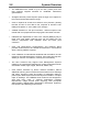
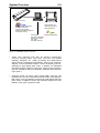
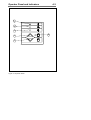
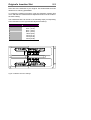
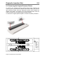
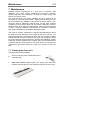
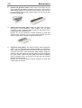
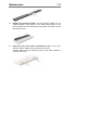
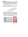
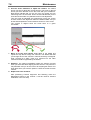
CHROMA 8040, 6040, 3040 Wide Format Color Scanner Operator’s Guide Internet info:http://www.contex.com Contex document no.: CHROMA/OPG/001 (1.0) Copyright Contex A/S, April 6, 2001 No part of this publication may be reproduced, stored in a retrieval system, or transmitted, in any form or by any means, electronic, mechanical, photocopying, recording or otherwise, without the prior written permission of the publisher. Contex A/S reserves the right to modify the information given in this publication without prior notice. The Contex scanner products are covered by one or more of the following patents: 5.117.295, 5.377.020, 5.502.578, 5.640.465, 5.642.207 other patents pending in the US and elsewhere. I Preface The CHROMA Wide Format Color Scanners provide complete solutions for scanning drawings, maps and pictures for use with Color reproduction, Color Copying, CAD, GIS, DTP and Archival programs. The built-in dedicated Color feature extraction hardware and highspeed Digital Image Processing (DIP) does image processing and enhancement in real time. This guide explains how to operate and maintain your Wide Format Color Scanner. It assumes basic knowledge of your computer and operating system and does not repeat material from their documentation. SYSTEM REQUIREMENTS • PC or supported workstation. • The SCSI interface kit matching your your workstation. • Scanner Maintenance Kit that came with your scanner. • WIDEimage or JETimage software for activating and controlling your scanner. RELATED PUBLICATIONS The "OPERATIONS GUIDE" which came with your computer. The "JETimage or WIDEimage USER's GUIDE". The "README.TXT" file on the distribution diskettes. Use your text editor to look for latest news and updates. II Table of Contents 1. Introduction 1-1 2. CHROMA System Overview 2.1 Software 2-1 2-4 3. Operating Modes 3.1 RGB mode 3.2 Indexed color mode 3.3 Feature extraction (classified) color mode 3.4 Graytone mode 3.5 B/W modes 3.6 B/W Copy Modes 3.7 2D-Sharpening, 2D-Softening and 2D-Blur 3.8 Resolutions, Pixel Distance and Scanwidth 3-1 3-1 3-1 3-1 3-2 3-2 3-2 3-3 3-3 4. Operator Panel and Indicators 4.1 Paper Feed/Forward Key & Ready indicator 4.2 Paper Reverse Key 4.3 Power On Indicator 4.4 Wait Indicator (Warm Up) 4.5 Diagnostic Indicator. 4-1 4-1 4-1 4-2 4-2 4-2 5. Original’s Insertion Slot 5.1 Rulers 5.2 Scanning Thick Media 5.3 Removing the Original Pressure Platen 5-1 5-1 5-2 5-5 6. Installation 6.1 Set up the scan station 6.2 Smart Card 6.3 Install Maintenance software and Drivers 6.4 Connection through the SCSI interface 6.4.1 Step 1: Install the SCSI host adapter board 6.4.2 Step 2: Install the SCSI driver software 6.4.3 Step 3: Connect the scanner to the PC 6.4.4 Step 4: Set the scanner DIL-switches 6.5 Installation Verification 6.6 Preliminary Maintenance 6-1 6-1 6-1 6-1 6-2 6-3 6-3 6-3 6-4 6-8 6-9 7. Maintenance 7.1 Cleaning the Scan Area 7.2 Camera Alignment 7.3 Calibrate the Scanner 7.4 Camera Out of Light Error 7-1 7-1 7-4 7-7 7-8 III 8. Appendix A: CHROMA specifications 8-1 9. Appendix B: Regulations 9.1 FCC Regulations 9.2 EC Regulations 9-1 9-1 9-2 10. Appendix C: Program License Agreement 10-1 11. Appendix D: Important Safety Instructions 11-1 12. Appendix E: Index 12-1 IV Introduction 1-1 1. Introduction The Contex CHROMA Wide Format Color Scanners are cost effective solutions for large format, high volume color scanning. This guide applies to the following models: • FSC8040 CHROMA Wide Format Color Scanner scans originals up to 40” Scan Width, and up to 800dpi resolution. ADL+ and 2DSharpen and Soften filters • FSC6040 CHROMA Wide Format Color Scanner scans originals up to 40” Scan Width, and up to 800dpi resolution. 2D-Sharpen and Soften filters • FSC3040 CHROMA Wide Format Color Scanner scans originals up to 40” Scan Width, and up to 600dpi resolution. The 40-inch wide imaging area handles color posters, color architectural drawings, maps, photos and fine art. The CHROMA can scan up to 0.6-inch (15mm) thick originals such as foamboards, gatorboards etc. The CHROMA Color Scanner together with a large format ink-jet printer forms the perfect large format digital copier. Embedded on-the-fly color feature extraction provides fast and easy classification and reduction of scanned colors to match those containing information in the scanned original. The built-in advanced Digital Image Processing (DIP) performs image enhancement in real time, and the unique built-in Area Diffusion Logic (ADL+) available with the FSC8040 scans and prints even the most demanding B/W and graytone documents with pleasing shades of gray at very high speeds. The ultrafast industry standard SCSI I/F and WIDEimage or JETimage software gives you full control over all of the scanner’s special scan modes and features. The WIDEimage and JETimage software is available in WINDOWS-98, WIDOWS-2000, WINDOWS-NT editions for PC workstations. 1-2 Introduction The CHROMA Color Scanners are designed to work with many types of scanning applications: • Reproduction (Large Format Color Copying) Join the CHROMA Color Scanner with a large format ink-jet printer to form an ideal large format digital color copier, handling large color posters, color drawings, maps, photos and fine art. • CAD (Computer Aided Design) The Wide Format Color Scanner scans, in color or B/W, drawings and documents into computers and performs color Feature Extraction so they can be used with CAD programs. • Mapping/GIS (Geographic Information Systems) The Wide Format Color Scanner scans maps and drawings for input and editing in GIS systems. An important advantage is the built-in color feature extraction which separates and combines map elements by their color. • DTP (Desk Top Publishing) The Wide Format Color Scanner scans large drawings and pictures to be used in technical documents, brochures, Data sheets, ads, etc.alid out woth popular DTP applications. • Archival The Wide Format Color Scanner scans large drawings, maps and pictures onto hard disks or CD-ROMs for on-line access by drawing database systems. The built-in Feature Extraction and Indexed Color mode significantly reduce file sizes and save disk space. Introduction Figure 1-1 The CHROMA Large Format Color Scanner 1-3 System Overview 2-1 2. CHROMA System Overview The CHROMA Wide Format Color Scanners, incorporate three 5350 RGB-triplet pixels, tri-linear color CCD cameras (21.400 RGB-triplets), and have color balanced stabilized fluorescent lighting and individual adaptive light compensation on each pixel. There are three CHROMA models and they include the following features: • FSC8040 CHROMA Wide Format Color Scanner, up to 800 dpi scan resolution at all original sizes in 24 bit RGB, color feature extracted or indexed, graytone and raster modes. Digital Image Processing includes: 2D-Sharpening and softening, Color Feature Extraction, 2D-Adaptive Thresholding and ADL+ copying with grayshades. Scanning Speeds: 200dpi: 2.5”/sec., 300dpi: 1.7”/sec. and 400dpi:1.3”/sec. • FSC6040 CHROMA Wide Format Color Scanner, up to 800 dpi scan resolution at all original sizes in 24 bit RGB, color feature extracted or indexed, graytone and raster modes. Digital Image Processing includes: 2D-Sharpening and softening, Color Feature Extraction, 2D-Adaptive Thresholding. Scanning Speeds: 200dpi: 1.7”/sec., 300dpi: 1.3”/sec. and 400dpi: 1.0”/sec. • FSC3040 CHROMA Wide Format Color Scanner, up to 600 dpi scan resolution at all original sizes in 24 bit RGB, color feature extracted or indexed, graytone and raster modes. Digital Image Processing includes: Color Feature Extraction, 2DAdaptive Thresholding. Scanning Speeds: 200dpi: 1.3”/sec.and 300dpi: 1.0”/sec. and 400dpi: 0.8”/sec. • Connection to up to two computers simultaneously via dual ultrafast SCSI Interfaces. This gives you the option to set up the scanner in both a color copy system configuration and a scan-to-file system configuration without moving cables between devices. • Scanning of documents/media sized from A5 up to larger than landscape A0/E-Size, 40” wide (1016mm). Media width: 6” to 51.5” (152 to 1310 mm). The scanning area is of unlimited media length. 2-2 System Overview • The CHROMA scans media of up to 0.6 inch (15mm) thick and thus supports originals mounted on cardboard, foamboard, gatorboard etc. • All digital cameras provide superior point-of-origin color capture for low noise and extended dynamic range. • Color is captured at 36 bits for maximum color precision, passing the best 24 bits of color data to the computer to enhance color fidelity and capture of even subtle color changes. • Variable resolution in one dpi increments - assures superior color results with color peripherals and varying RIP color dither cell size. • Individual tone adjustment for each color channel (RGB) by way of three color tone tables (gamma) that can be loaded into the scanner. Independent user definable white and black point correction. • Color and Monochrome 2D-sharpening and softening filters provides enhancement of fine details and reduction in moire effects when scanning halftone originals. • Color calibration to international standards with the ANSI-IT-8 color reference card delivered with the scanner, thus improving long term stability of scanner color balance, linearity and chromaticity. • The color scanners fully support Color Management Systems (CMS) by the international standard ICC profile (International Color Consortium: Kodak, Agfa, Apple, Microsoft, Adobe, etc.) • Color feature extraction by built-in real-time hardware, without additional scanning time overhead. Extracts features from drawings and maps, enhances clarity and quality of duplicated, faded or printed (color dithered) documents and improves details in complex maps or drawings. The CHROMA Color Scanners are designed to work with many types of scanning applications including Reproduction (Large Format Color Copying), CAD (Computer Aided Design), Mapping/GIS (Geographic Information Systems), DTP (Desk Top Publishing) and Archival. System Overview 2-3 PC or WORKSTATION CHROMA COLOR SCANNER Scanning /Image Enhancement Color Feature Extraction Conversion, De-speckling, De-skewing, Rotation & Alignment Viewing and Zooming INKJET PRINTER/ PLOTTER Large format full color output/copying to ink-jet plotter supported by or third party software RIPS File Formats: (more than 50 selectable including color formats: TIFF, JPEG, PCX, BMP, RAS, RTL) Figure 2-1 CHROMA System Overview • These color scanners work also as superior monochrome scanners, providing clean, crisp scans from even poor quality drawings, blueprints, etc. Image processing and enhancement options include: 2D-Adaptive Thresholding, Photo mode, histogram analysis, on-line threshold variation, on-line de-skewing and despeckling for high quality raster scans. In addition, the CHROMA FSC8040 supports reliable monochrome copying where shades of gray are maintained with the FSC8040’s advanced Area Diffusion Logic (ADL+). • Scanning modes: 16 million colors (24-bit RGB), 8-bit and 4-bit indexed color, 8-bit and 4-bit feature extracted color, 8-bit graytone, B/W raster: fixed, 2D-Adaptive threshold and black/white dithered photo mode. In addition to these, the FSC8040 supports the Area Diffusion Logic (ADL+) graytone mode. 2-4 System Overview 2.1 Software WIDEimage The WIDEimage scanning software offers optimal support for your scanner. This efficient tool is designed specifically for your scanner and gives you access to all the scanner’s built-in features. The program produces a multitude of industry standard color, graytone and B/W output image file formats compatible with CAD, GIS, RasterEditor, Raster-to-Vector, Digitize, Overlay, Color reproduction and copying, RIP, and Archiving programs for Editing, Storing, Conversion and Print/Plot of scanned drawings, maps, etc., to be used with Graphics art, Reprographics, CAD, GIS, DTP and Color Copying systems. WIDEimage supports electronic Rotation and Alignment, as well as Converting, Viewing, Zooming and Printing of scanned originals. With WIDEimage’s Feature Extraction tools you can automatically generate and edit color look-up tables for downloading into the scanner's built-in feature extraction engine. The intuitive user interface includes Color Wheel and Color Histogram views, tools for merging marked or similar colors, Explode Color, removing marked similar or minor colors, Insert Color, and Import Colors. JETimage This copy program is built to satisfy the needs of scanning and copy professionals and designed on the basis of their experiences and specific daily problems. It enables users to make large format copies in vivid colors, quality enhanced graytones and crisp black and white. JETimage copy software is available in two editions: JETimage BASE and JETimage PRO. The application is designed to interface your Contex Scanner with a wide range of popular printers for large format copying. JETimage is a powerful, professional tool enabling easy production of vivid high quality color corrected copies and also exploits the scanner’s System Overview 2-5 monchrome enhancement features for demanding black and white copy assignments. JETimage can come with both touch-screen and conventional mouse-keyboard interfacing. The PRO edition enables Copy-to-File and Print-From-File features, accounting, Paneling and Nesting. WIDEcapture for Photoshop Wide Format Scanning Software for Macintosh and Windows as a Plug-in for Adobe Photoshop. WIDEcapture is a compact application designed to interface your scanner with advanced graphics software on an Apple Macintosh or Windows-based platform. The application is developed for usage with Adobe Photoshop – a leading image software application among graphics professionals. The software is designed as a plug-in, meaning it is a full software program that extends the functionality of the Adobe Photoshop program by enabling access to Wide Format Scanning. You install the program into Adobe Photoshop’s plug-in folder and just select the application through Photoshop’s File menu. WIDEcapture imports images from the scanner into the Photoshop image editor. You can then use Photoshop’s wide range of image manipulation options, just as if you had opened an image file from your hard disk. WIDEcapture for AutoCAD Wide Format Scanning Software for direct scanning into AutoCAD 2000 on Windows platforms. WIDEcapture for AutoCAD is a compact application designed to interface your Wide Format Scanner with the advanced CAD software AutoCAD 2000. When you install this plug-in software, a new menu item called "Scanned Raster Image" is entered in the Insert Menu on your AutoCAD interface. Selecting this item activates a Wide Format Scanning interface that contains all the features known from the WIDEimage Scan Screen, including the split preview screen and special tool buttons. Operating Modes 3-1 3. Operating Modes The CHROMA Color Scanners work in six operating modes: • 24 bit RGB color mode • 8-bit indexed color mode • 8-bit feature extraction color mode • Graytone mode (256 graytones) • B/W modes (bitmapped, 2-level and 2D-adaptive) • B/WCopy modes with Dual 2D-Adaptive processing. 3.1 RGB mode Full 24-bit true color mode for 16.8 million colors. 3.2 Indexed color mode An effective method for scanning documents that display a limited range of colors, is to map true colors to a selected color palette. The palette is automatically generated by an adaptive color optimizing prescan of the original. The scanner on-board color transformation to a 16- or 256-color palette greatly reduces the data volume, increases scan speed and minimizes disk storage requirements by only requiring 8-bit per color pixel (compared with 24-bit in true color mode). 3.3 Feature extraction (classified) color mode Real-time color classification mode sorts the observed color features in the document into a set of color categories by on-board mapping through a classified color LUT (Look Up Table). The classified color LUT is generated by the user through the tools in WIDEimage and then downloaded into the scanner. The user only has to create the LUT once for a whole class of documents. The scanner on-board color mapping through a 256 classified color LUT greatly enhances clarity and quality of duplicated, faded or printed (color dithered) documents. It improves details in complex maps or drawings, increases scanning speed, and minimizes disk storage requirements. 3-2 Operating Modes 3.4 Graytone mode In Graytone mode, the actual graylevel of each pixel is scanned; 256 levels are recognized, corresponding to 1 byte (8 bits) per pixel. This results in graytone files that are 8 times larger than uncompressed files scanned in Line mode at the same resolution; for example, an ESize drawing scanned in graytone mode at 300 dpi has a file size of 150 MByte, compared with typical 0.4 -1.0 MByte for a compressed file in Line mode. 3.5 B/W modes In this mode, the MAGNUM Color Scanner outputs each scanned pixel as a single bit, either black (1) or white (0), depending on whether its gray level is below or above the threshold. Both fixed level and 2D-Adaptive thresholding are supported. 3.6 B/W Copy Modes The copy modes incorporate Dual 2D-Adaptive processing with different combinations of ADL+ Error Diffusion Halftoning, 2DBackground suppression, 2D-Auto edge enhancement and 2DAdaptive thresholding. The copy modes are ideal scanning wide format documents that are intended for re-printing. The ADL+ Error Diffusion Halftoning supports visibility of graytones in printed output by adding toned shades of gray in regions between black and white. The copy modes are described in the table below: Copy Mode Image Processing Usage B/W Copy Normal ADL+ Error diffusion halftoning 2D-Auto edge enhancement 2D-Adaptive background suppression ADL+ Error diffusion halftoning 2D-Adaptive thresholding 2D-Adaptive background suppression Halftone copy to print of all normal originals ADL+ Error diffusion halftoning Halftone copy to print of continuos shades of gray such as in photos. B/W Copy Adaptive B/W Copy Photo Halftone copy to print of Sepia, Blueprint and other originals with heavily distorted foregrounds and backgrounds where the shades making up the image “noise” are close to the shades making up the image’s data and hard to differentiate. Operating Modes 3-3 3.7 2D-Sharpening, 2D-Softening and 2D-Blur Through the WIDEimage and JETimage applications, you can manually set and control sharpening, softening and blurring filters, giving you rich possibilities for combining effects to obtain perfect enhancement results. For example, you may have an image with details (such as text or lines) you wish to sharpen. But if the image also contains large concentrated areas of colors or graytones, sharpening will make unwanted noise to appear in the scanned image. By using the sharpen filter together with the blur filter, you can obtain the desired sharpened edges without creating the unwanted noise. Both filters can be set at different levels for ultimate control of effects. The B/W Copy Normal scanning mode incorporates 2D-Auto edge enhancement, with automatic, on-the-fly sharpening of your image. 3.8 Resolutions, Pixel Distance and Scanwidth For CAD applications Below is listed the distance (both horizontal and vertical) between each pixel at different resolutions* : Resolution 200 dpi 300 dpi Distance between pixels 0.1270 mm. 0.0846 mm. 400 dpi 0.0635 mm. 600 dpi 0.0423 mm. 800 dpi 0.0317 mm. *With all CHROMA scanners - resolutions are variable and can be set in 1 dpi increments from 50 to max. scanner resolution (800 or 600 dpi). The resolution, in dpi, is always set from the WIDEimage application just before scanning. 3-4 Operating Modes Scan-width Scan Width is also set from WIDEimage. Use the units of the ruler printed near the original’s insertion slot on the CHROMA Scanner to determine the value. The user can select through WIDEimage the preferable insertion method for the original. Either side aligned loading or centered loading can be selected. The ruler above the insertion slot is used with side aligned insertion (at the ruler’s zero mark), and below the slot are the standard size markings used with centered insertion. The following table shows the number of pixels (RGB triplets) per line resulting from various combinations of resolution and scan-width settings in scan units on the side aligned insertion (top) ruler: Resolution/ Scan Width 9.4 (40.0”) 600 dpi 400 dpi 300 dpi 200 dpi 24,000 16,000 12,000 8,000 8.0 (34.0”) 20,352 13,568 10,176 6,784 6.0 (25.4”) 15,240 10,160 7,620 5,088 4.0 (17.0) 10,176 6,784 5,088 3,392 3.0 (12.7”) 7,620 5,080 3,810 2,544 2.0 (8.5”) 5,088 3,392 2,544 1,696 Operator Panel and Indicators 4-1 4. Operator Panel and Indicators The CHROMA Color Scanner Operator Panel layout shown overleaf is divided into two keys and four indicators. The two operating keys are positioned at the bottom: The Paper Reverse key (C), and the Paper Feed/Forward key (A) with a Ready indicator (B) attached. There are three indicators at the top: Power on (D), Wait (E), and Diagnostic (F). The function of the keys and indicators are as follows: 4.1 Paper Feed/Forward Key & Ready indicator A B • Insert the drawing face down into the scanner’s Insertion Slot, the green Ready indicator (B) turns ON when the drawing is correctly positioned. • Now press the Feed Forward key (A), and the drawing moves into the start-of-scan position (if auto-load is selected in WIDEimage loading will take place automatically). • The Ready indicator stays ON, signifying that the scanner is ready to be controlled from the computer. • During scanning the Ready indicator will blink. • At end of scanning the Ready indicator will stop blinking and again turn ON signifying that scanning can be repeated from the computer, or else terminated by pressing the Paper Feed/Forward key to eject the drawing from the scanner. • Pressing the Paper Feed/Forward key during scanning stops the scanning process and feeds the original as long as the key is pressed. 4.2 Paper Reverse Key C The Reverse key stops the current scanning process and reverses the original while the key is pressed. 4-2 Operator Panel and Indicators 4.3 Power On Indicator D Lights when the scanner is ON and is receiving power. 4.4 Wait Indicator (Warm Up) E Lights when the scanner power is turned on, and stays on during the internal diagnostic and stabilization phase. Keyboard input is prevented during this time. The Wait Indicator Flashes if auto-adjustment of the scanner's light profile, stitching etc., has been suspended for about two hours. This may happen when operating the scanner in "Extended Thickness" mode over an longer period of time. In these cases, the Original Pressure Platen should be returned to the NORMAL position for a short while to trigger the scanner’s auto-adjustment routine. 4.5 Diagnostic Indicator. F Flashes if an error is detected by the built-in diagnostic. Simultaneous flashing by both the "Diagnostic" and the "Wait (Warmup)" indicators may mean that the scanning area needs cleaning. See Chapter the "Maintenance" for instructions on cleaning the scanning area. Operator Panel and Indicators 4-3 F E D A C Figure 4-1 Operator Panel B Original’s Insertion Slot 5-1 5. Original’s Insertion Slot 5.1 Rulers The Original’s insertion slot shown below is marked with a measurement ruler on top. The ruler can be slid out and flipped over to select/change your preferred measurement units – inches or millimeters. Measurements are also given in scanner units. The top ruler corresponds to right side aligned original feeding. Below the ruler are marked common original sizes for guidance with optional centered feeding. Insertion alignment of originals, right side aligned or centered, is operator selectable from the WIDEimage scanning software. Center feeding is often preferable as the original is positioned symmetrically on the feed rollers during scanning. The Scan-width, measured in inches, mm or scanner units is likewise set from WIDEimage. Figure 5-1 Original Insertion Slot 5-2 Original’s Insertion Slot The following table shows some of the most common drawing widths and the corresponding scan-width settings in inches, mm and scanner units: Scanner Units Original Drawing Width*: Minimum media size of scanner 6.0"/152mm 1.4 Minimum Scan Width (A5) 6.0"/152mm 2.0 A-Size (letter) and approx. A4 8.5"/216mm 2.6 B-Size (11") 11.0"/280mm 2.8 A3 (297mm) 11.9"/302mm 3.0 Approx. A3 and approx. B-Size 12.7"/323mm 3.9 A2 (420mm) 16.5"/420mm 4.0 C-Size and approx. A2 17.0"/430mm 5.2 D-Size (22") 22.0"/560mm 5.5 A1 (594mm) 23.3"/592mm 6.0 Approx. A1 and approx D-Size 25.4"/646mm 7.8 A0 Portrait (841 mm) 33.1"/840mm 8.0 E-Size and approx. A0 34.0"/862mm 9.4 Maximum ScanWidth of scanner 40.0"/1016mm Maximum Media size of scanner 51.5"/1310mm *The required setting for an original drawing can be measured, with the original inserted into the scanner, using the ruler printed on top of the Original Insertion Slot on the CHROMA Color Scanner. Then, you just enter your measurement in the width setting box in WIDEimage’s scanning setup dialogs 5.2 Scanning Thick Media Scanning needs are not always limited to convenient paper thin media. Many industries, such as reprographics and GIS, will find the need to digitize or copy images printed or pasted on thicker media such as cardboard, foamboards, gatorboards etc. To support such needs the CHROMA color scanner allows you to change the insertion slot space on your scanner from 0 to 15 mm (0 to .6”) in small steps so you can Original’s Insertion Slot 5-3 fit the slot to the thickness of your original. This feature adds an extra dimension to scanning possibilities. To change the insertion slot space, open the Original’s Insertion Slot cover and slide the media thickness adjustments found at each side to the same setting. The media thickness can be set in the following steps (corresponding to the indications on the right and left adjustment sliders): Step 0 (Normal Position) 1 2 3 4 5 6 7 MaximumThickness 2mm (0.08”) 4mm (0.16”) 6mm (0.24”) 8mm (0.32”) 10mm (039”) 12mm (0.47”) 14mm (0.55”) 15mm (0.60”) Figure 5-2 Media Thickness Settings 5-4 Original’s Insertion Slot The Normal position (Step 0: 2mm/0.08”) is detected by a sensor in the scanner. Auto-adjustment of the scanner’s light profile, stitching etc. only takes place in the Normal position. With extended media thickness positions, the last performed auto-adjustment is stored and utilized. This means that you should from time to time return to the normal position, and especially when turning the scanner on, to allow it to auto-adjust. The Normal position also gives the highest scanning speed. In the extended media thickness positions, scanning speed is automatically reduced. Heavy cardboard, foamboard etc. require lower scanning speeds to hinder unwanted start/stops caused by the media’s low flexibility. Thick stiff originals will rest on top of the scanner rollers and thus raise a small distance over the glass plate, which can lead to changes in the stitching of images at points between the cameras (overlapping or missing pixels). The stitching parameters can be modified in the WIDEimage Scanner Setup dialog. The modified stitching setup is only active in the extended media thickness positions and not in the Normal Position, where the standard stitching setting is used. To modify the stitching insert your thick original in the scanner, scan with WIDEimage and check the result in the viewer for overlapping or missing pixels in the camera transition areas. Then adjust the value in the WIDEimage Scanner Setup dialog. Repeat scanning and adjustment until the effect is minimized. The modified stitching parameters will automatically be selected when in one of the extended media positions. Scanning thick originals can give distortions when the front edge meets the exit rollers or the trailing edge leaves the entry rollers. To omit this, the leading and trailing edges are by default skipped when in one of the extended media thickness positions. Leading/trailing edge skipping can be turned off through the WIDEimage Scanner Setup dialog. To facilitate scanning of thick originals in the extended media thickness positions it is important to insert the original center aligned and to help support the original during scanning. This should be done both at the entrance side and the exit side of the scanner. Original’s Insertion Slot 5-5 5.3 Removing the Original Pressure Platen To remove the original pressure platen fixture when cleaning the scanning area, press down the platen fixture while sliding the left and right extended media thickness adjustment sliders fully towards the middle of the platen. This allows you to fully disengage them from the scanner and lift out the original pressure platen fixture. To reinsert the original pressure platen, reverse the above procedure. Figure 5-3 Slider in the exit position 5-6 Original’s Insertion Slot A small locking pin will keep the slider in the exit position to facilitate removal and insertion of the pressure platen. Installation 6-1 6. Installation 6.1 Set up the scan station Your Wide Format Scanner should be placed either on a sturdy table or the specially designed stand-alone floor stand. The specially designed floor-stand is required for mounting the optional Copy Kit (PC and Screen holders). Make sure there is enough space behind the scanner to allow the media to run out. Thick stiff media requires space that is at least as large as the media length. Slots or openings in the cabinet at the back or bottom are provided for ventilation. This ensures reliable operation of the product and protects it from overheating. These openings must never be blocked or covered by placing the unit on a bed, sofa, rug, or other similar soft surface. Your scanner should never be placed near or over a radiator or heat register. You should not place the scanner in a built-in installation unless proper ventilation is provided. 6.2 Smart Card Check that the scanner Smart Card is correctly installed (contact side downwards) and corresponds to your scanner model. You will find the Smart Card in the small drawer labeled “PUSH” behind the scanner front streamer (remove the streamer to access the drawer). The scanner will only function correctly when a Smart Card is inserted. Notice that the SCSI DIP switch controls are in the Smart Card drawer. Setting the DIP switch controls is described under the sections for SCSI installation. 6.3 Install Maintenance software and Drivers You are now ready to install the setup controls and maintenance utilities for your scanner. Insert the Maintenance CD and click the relevant installation option(s). Follow the instructions on your screen. Be sure to refer to the separate driver documentation and READ-ME files for last minute updates/instructions on installation of drivers. 6-2 Installation 6.4 Connection through the SCSI interface SCSI stands for Small Computer System Interface and is pronounced "skuzzy". It's a standard for connecting peripherals to your computer via a standard hardware interface, which uses standard SCSI commands. SCSI is an advanced interface that offers a level of performance, expandability and compatibility unmatched by other current PC interfaces. In order to put together a PC with a SCSI interface for your scanner you'll need: • A SCSI host adapter board (also called a SCSI controller) • SCSI driver software • A SCSI cable The interface kit contains all you need to get your SCSI interface up and running. A SCSI cable is supplied with your scanner. The interface kit contains detailed documentation for installing the SCSI host adapter board and the SCSI driver. Note: If your PC already has a built in SCSI board you might be able to use that instead. However for best performance, we strongly recommend that you use the board and driver delivered with the Contex Interface Kit. Regulatory Notice: This product has been tested to comply with the EMC Standards EN55022 and FCC, Part 15. To maintain compliance, only use shielded SCSI interface cables. How to set up the SCSI interface Setting up the SCSI Interface requires the following steps. Each step is described in detail in the following sections: 1. Install the SCSI host adapter board into an empty slot in PC. 2. Install the SCSI driver software that came with the Interface kit. 3. Connect the scanner to PC. 4. Set scanner DIL switches if the default settings require changing. Installation 6-3 5. Set scanner DIL switch 4 termination properties. 6.4.1 Step 1: Install the SCSI host adapter board 1. Set the PC-system unit power-switch to OFF. 2. Set any external device power switches to OFF (such as printers, displays etc.). 3. Unplug the PC-system unit and all other devices from the wall outlet. 4. Remove the cover of your computer to expose the expansion slots. 5. Align and insert the SCSI host adapter board into an empty slot. 6. Use the expansion slot panel screw to secure the host adapter to the computer frame. 6.4.2 Step 2: Install the SCSI driver software SCSI driver installation will be dependent on your windows operating system. Follow the instructions for your operating system described in the driver documentation that came with your interface kit. 6.4.3 Step 3: Connect the scanner to the PC 1. Be sure to disconnect the power cable from the scanner. If power runs through the scanner at this point it may damage your SCSI host adapter. 2. The SCSI connectors are accessed from the back of the scanner and found underneath the left side (when facing the back). There are two SCSI scan connectors SCAN SCSI 0-A and SCAN SCSI 0-B. The COPY-SCSI connector (1) is only used when a separate Copy-PC configuration is attached simultaneously with the Scanto-File-PC (SCAN-SCSI). 3. Connect the SCSI cable that came with your scanner to one of the two SCSI connectors (0-A or 0-B). The extra connector is for only for daisy-chaining another device to the system. 4. After the SCSI cable has been inserted in the connector the power cable can be inserted into the scanner and plugged in. 6-4 Installation 6.4.4 Step 4: Set the scanner DIL-switches The DIL-switches are used for setting up of the scanner’s SCSI connection ports, and for selection of the scanner test mode and the scanner forced boot start up mode. The DIL-switches are set from the factory to default settings that apply to most common configurations so usually you will not have to change them. Best scanning performance is obtained with only one device on the SCSI bus. However, if your configuration requires more than one device on the bus, you may need to change the DIL-switch settings. The factory default DIL-switch settings and the DIL-stitch Value table are shown on the following page. Use the table and the following instructions for each switch to determine your DIL-switch settings if you need to change them. Before proceeding with setting the switches you must turn the scanner power off. Removing and inserting the Smart Card (see below) while power is on can damage the scanner. Installation 6-5 You will find the DIL-switches in the small Smart Card drawer labeled “PUSH” behind the scanner front streamer. To access the switches remove the streamer, push the drawer inwards and release so it pops open and remove the Smart Card. Figure 6-1 Access the DIL-switches Important: Remember to reinsert the Smart Card when finished setting the DIL-switches and before turning power on. SCSI-DIL switch, Factory Default Setup: OFF SCSI Device Address 1 SCSI Device Address 2 SCSI Device Address 3 SCAN-SCSI (0-A & 0-B)Termination 4 SCAN-SCSI (0-A & 0-B) No Synchr. Transfer 5 COPY-SCSI (1) 6 No Synchr. Transfer Force Boot Start up 7 Test Mode 8 ON 6-6 Installation Device number setup – switch 1,2,3 Make sure the power to the computer and the scanner are OFF when setting the SCSI device number, as the switch settings are only read from the scanner DIL-switch during the scanner’s power up. You can set up the SCSI device no. for the scanner to any unused SCSI device no. The combination of the three SCSI Device Address switches determines the scanners device no. To set the SCSI device no. to the one required, you simply set the switches 1, 2 and 3 to the combination of ON/OFF values specified in the table below. The scanner is set as SCSI Device no. 2 from the factory. 1 2 3 SCSI device no. 0 ON ON ON SCSI device no. 1 OFF ON ON *SCSI device no. 2 ON OFF ON SCSI device no. 3 OFF OFF ON SCSI device no. 4 ON ON OFF SCSI device no. 5 OFF ON OFF SCSI device no. 6 ON OFF OFF SCSI device no. 7 OFF OFF OFF SCSI device no / Switch combination: * Factory Default SCSI built-in active termination – switch 4 Your scanner has a built-in active SCSI termination that works better than a passive terminator at the device’s high transfer rates. The built-in active termination for the SCAN-SCSI bus is enabled by setting switch 4 on the SCSI switch to ON and disabled by setting it to OFF. The COPY-SCSI bus has only one connector and will therefore always have active termination on. If the scanner is the last device on the SCSI bus, make sure the builtin active SCSI termination is turned on. If the scanner is not the last device make sure switch 4 is turned off. (see following illustrations). Important: Never set switch 4 to ON and use a terminator block at the same time. Installation 6-7 The following 3 scenarios show how to terminate the SCSI bus correctly: A. The Scanner is the only external device on the SCSI bus Switch 4 must be ON SCSI SCANNER Host Computer B. The Scanner is the last device on the SCSI bus Switch 4 must be ON SCSI SCSI SCANNER CD-ROM Host Computer C. The Scanner is not the last device on the SCSI bus Must be terminated Switch 4 must be OFF SCSI SCANNER SCSI CD-ROM Host Computer Note: If the scanner is connected to an existing SCSI controller in the PC that is used together with an internal SCSI device (f.ex. a hard disk), make sure that the on-board SCSI termination is removed before attaching the scanner. Please refer to the documentation for the internal device for instruction. 6-8 Installation Troubleshooting and Test Controls – switches 5, 6, 7 and 8 Switch 5. SCAN-SCSI (SCSI connectors 0A & 0B) - No synchronous transfer: Disables SCAN-SCSI synchronous transfer mode (reverts to asynchronous transfer). Only use this mode for testing as it slows down the scanner. Switch 6. COPY-SCSI (SCSI connector 1) - No synchronous transfer: Disables COPY-SCSI synchronous transfer mode (reverts to asynchronous transfer). Only use this mode for testing as it slows down the scanner. Switch 7. Force boot start up: If a malfunction occurred during an update of the scanner firmware, this switch forces the scanner into firmware boot mode, enabling you to download the firmware again. Switch 8. Continuous test mode: The continuous test mode is only used for maintenance and the scanner is inaccessible. Important: For normal scanning, make sure that none of the troubleshooting and test control switches are on. 6.5 Installation Verification Turn on the power to the computer and the scanner. If you have not yet done so, install the Scanner Maintenance Software and copy/scanning applications: JETimage, WIDEimage or WIDEcapture on your PC. Follow the installation instructions supplied with each item. Start up the maintenance software (Start – Programs – Scanner Maintenance). The program will detect your scanner if it is installed correctly and display an introduction to the maintenance wizard. Otherwise, a message will inform you that your scanner could not be detected. If this is the case turn off power to all connected devices and reboot the system. You can also verify correct setup and configuration through JETimage or WIDEimage. These programs will detect your scanner and display the model ID in the Scanner Setup dialogs. Insert a doument and Installation 6-9 perform a simple scan by hitting the Scan button (WIDEimage) or Copy button (Jetimage). 6.6 Preliminary Maintenance Once you have setup your scanner and verified your installation, it is important that you run your first maintenance session before working with the scanner. Shipping and transportation of your scanner from the factory may have affected the camera positions and it would be a good idea to align the cameras and then color calibrate. Follow the instructions described under the chapter on Maintenance in this Operators Guide. Maintenance 7-1 7. Maintenance Regular scanner maintenance is a sure way to minimize costly downtime. The three routine maintenance procedures cleaning, camera alignment and calibration will improve image quality and reduce your service costs. The three functions are closely entwined and they should all be performed in a maintenance session, starting with cleaning the scan area and ending with calibration. The reason for this is simple. If you clean the glass or adjust the cameras then you will have changed conditions in the scanning area and will need to calibrate in order to readjust black, white and color interpretation. This works the other way as well – scanner calibration must always be preceded by cleaning and camera alignment to get reliable calibration results. The tools for scanner maintenance, including the Maintenance sheet for alignment and calibration were supplied with your scanner. The Scanner Maintenance CD-ROM that came with your scanner contains wizards that will check your scanner and guide you through the steps for perfect scanner camera alignment, stitching and calibration. Please install the Scanner Maintenance program from the CD-ROM before continuing with the steps below. It is a good idea to run through the maintenance procedures when you setup your scanner for the first time. 7.1 Cleaning the Scan Area The glass plate and white platen. 0 Turn the scanner power off and disconnect the power plug 1 Open the scanner cover. Place your fingers just inside the insertion slot and flip the cover upwards to expose the scan area. 7-2 Maintenance 2 Remove the pressure platen. Press down on the platen as you pull the left and right sliders towards the scanner’s center until the metal safety buttons on each side of the scanner, pop up. Use the two handles to lift out the pressure platen as soon as you feel the sliders disengage. 3 Gently wipe the glass plate. Clean the glass with a lint-free cloth and a mild, streak-free, glass cleaner. Dry the glass completely using a separate clean, dry lint-free cloth like the one provided with the maintenance kit. Caution: do not use abrasives, acetone, benzene or fluids that contain these chemicals. Do not spray liquids directly onto the scanner glass plate or anywhere else in the scanner. 4 Clean the white platen. The white scanning area background platen is on the backside of the pressure platen you removed in step 3. Wipe the white metal area and the white nylon rollers with a lint-free cloth and a mild, streak-free, glass cleaner. Apply the cleaner to the cloth and then wipe the platen’s smooth metal and the nylon roller’s surface. Dry the platen and rollers completely using a separate clean, dry lint-free cloth like the one provided with the maintenance kit. Caution: do not use abrasives, acetone, benzene or fluids that contain these chemicals. Maintenance 7-3 5 Replace the pressure platen. Lift the pressure platen into its original position. Press down on the metal safety buttons to let the two sliders move back and lock the platen into place. Close the scanner cover. 6 Keep out dust and reduce maintenance time. Cover your scanner with the plastic dust cover when not in use. Caution: Make sure the scanner power is OFF when using the scanner dust cover. 7-4 Maintenance 7.2 Camera Alignment Height alignment and stitching Camera alignment tools: Adjustment Chart, 3C-Kit Screwdriver, Scanner Maintenance Software 0 The Scanner should be warm. Make sure that the scanner has been turned on for at least one hour prior to camera alignment. Slight light intensity changes and camera shifting can occur just after turning the scanner on and the warm-up time will ensure that light conditions and camera heights have stabilized. 1 Remove the front streamer. The camera alignment holes are behind the front streamer. Lift the end and pull the streamer out along its slot. 2 Locate the adjustment holes. The scanner’s cameras are labeled, from the scanner’s right edge, with letters A, B, C etc. The B camera is fixed and serves as the reference point for aligning the other cameras. You align a camera by turning its adjustment screw through the hole in front of the camera as described below in steps 3 to 7. Maintenance 7-5 3 Start the Scanner Maintenance Utility. Select Programs > Scanner Maintenance to start the Maintenance Wizard. The wizard will guide you through Camera Alignment, Stitching and Calibration. Click the Next button in the welcoming dialog to proceed with Camera Alignment. 4 Insert the Maintenance Sheet. The sheet’s printed side must be inserted face down. Align the midpoint arrow with the scanner’s midpoint arrow and feed the chart into the scanner. 5 Load the alignment status for Camera A. The scanner will immediately start scanning the chart and display the alignment status for the first camera - Camera A. The Alignment status can be judged by the evenness of the horizontal line. The scanner will automatically continue loading fresh views of the alignment status until you are finished. You can click with your mouse on an area in the view to zoom in on the alignment line if necessary. Use the Toggle Zoom button to change between zoom levels. 7-6 Maintenance 6 Use the arrow indicators to adjust the camera. The wizard shows you how to adjust the current camera. The arrow on the left shows you which direction to turn the screw with your screwdriver. Red arrows indicate that you are far from your target and can make large turns of the screw. Green arrows indicate that you are close and should make very delicate turns for fine adjustment. Turn the screw as indicated and continuously check your screen as fresh views of the alignment status are loaded. Make sure you let the wizard update the screen between each turn of the screw. The camera is aligned when the arrow turns to a green checkmark. 7 Move on to the next camera. Select Next in the wizard and repeat the step above to align the cameras. The Wizard will take you through each of the scanner’s cameras until they are aligned. Note: Camera B is static, used as a reference for the other cameras and will be bypassed by the wizard. 8 Stitching. The wizard immediately starts the stitching process when you click Next after aligning the last camera. The process is fully automatic and you do not have to do anything but wait for it to finish after which you have the option to check the results for each camera. Replace the front streamer. 9 After performing Camera Alignment and Stitching, leave the Maintenance Sheet in the scanner. It will be used for Camera Calibration in the next step Maintenance 7-7 7.3 Calibrate the Scanner Basic and color calibration Calibration tools: Maintenance Sheet Clean the scanning area and align the camera. Before you calibrate, make sure that you have gone through the first two C’s of maintenance – Cleaning the scan area and Camera Alignment. An unclean scanning area or unadjusted cameras will give you imprecise calibration results. The steps described here require that you have installed the Maintenance software that came with your scanner. 0 Scanner should be warm. Make sure that the scanner has been turned on for at least one hour prior to calibrating. Slight light intensity changes and camera shifting can occur just after turning the scanner on and the warm-up time will ensure that light conditions and camera heights have stabilized. 1 2 Start calibration in the scanner maintenance wizard. Normally you will enter the steps for calibration directly from Camera Alignment/Stitching through the Scanner Maintenance Wizard. If you have just aligned the cameras, then leave the Maintenance Sheet as it is in the scanner and press Next. However, if you have terminated the program before calibrating, start the Scanner Maintenance utility, insert the Maintenance Sheet and select the Skip to Calibration option. 7-8 Maintenance 3 Calibration Press the wizard’s Next button to start the Basic Calibration process. Color Calibration follows immediately after. The wizard will inform you when Calibration is complete and instruct you to remove the Maintenance Sheet. 4 Wrapping up. Calibration completes the maintenance process. Remove the Maintenance Sheet from the scanner. Return the sheet its protective cover and then place it the storage folder. Store the folder in a dry place and out of direct light. 7.4 Camera Out of Light Error The camera out of light error is shown by simultaneous blinking of both the "Diagnostic" and "Warm Up (Wait)" indicators. The camera out of light error occurs when one of the CCD cameras moves out of range and it does not receive enough light to function optimally. This could happen while making camera adjustments or during transportation of the scanner. The Wait (Warm Up) indicator will show which camera is out of light by the how many flashes per period it makes. The camera is indicated by the following table with A as the leftmost camera and D the rightmost: Camera A: 1 flash per period. Camera B: 2 flashes per period. Maintenance 7-9 Camera C: 3 flashes per period. Before proceeding with CCD camera height adjustment, perform the following for the camera that has the out of light error: 1. Turn the height adjustment screw eight turns clockwise. 2. Turn the scanner power off, and then on. If the error still shows, turn the height adjustment screw sixteen turns counterclockwise. 3. Turn the scanner power off, and then on. If the error still shows call maintenance to adjust the camera. Note: Camera-B is not user adjustable After clearing the "Camera out of light error", you will need to perform Camera Height Alignment and Calibration as described in previous sections. A: Specifications 8-1 8. Appendix A: CHROMA specifications CHROMA X040 Models 3040 6040 8040 Maximum Resolution (dpi): Variable resolution setting: from 50 dpi in one dpi increments Scan Speed: 400dpi Turbo, 24 bit RGB scans Digital Image Processing: Dual 2D-Adaptive enhancement processing. ADL+ error diffusion halftoning. 2D - Sharpening and Softening. 2D - Blur filter Color Feature Extraction 2D - Adaptive Thresholding. 600 X 800 X 800 X 1.3 “/s 1.7”/s 2.5”/s SW SW SW HW HW HW SW SW HW HW HW HW HW HW HW HW HW HW X X X X X X X X X X X X X X X X X X X X X X X X X X X X X X X X X X X X X X X X X X X X X X X X X X X X X X X X X X X X X X X X X X X X X X X X X X X HW = Image processing feature embedded in the scanner’s hardware SW = Image processing feature emulated in WIDEimage/JETimage Scan Modes: 24-bit color 8 bit Feature Extraction/indexed color 8-bit graytone with 256 gray levels. Copy modes with ADL+ Error Diffusion halftoning. 1-bit Black & White line mode Color Adjustment: 3x3 matrix multiplier Independent RGB tone curves (Gamma) Independent black-and-white point setting Sensors: Triple tri-linear color CCDs 15.900 pixels (RGB triplets) 36 bits of color data capture. Media and Scan Width: Media Width: 6.0 to 51.5" (1310mm.) Scan Width: 40 Inches (1016 mm.) Media Thickness: Up to 0.6” (15mm.) Dimensions: 61.4” wide x 7.3”high x 18.3”deep (1560 x 185 x 465 mm.) Weight: 65 kg Interface: Dual Ultrafast SCSI Light Source: Color matched fluorescent lamps Optics: Torsion stabilized for portability. Power: 110/220/240V, 60/50 cs, 180W Scanner Maintenance Kit Maintenance Software, Maintenance Sheet, Instructions Optional Interface Kit – WIDEimage Software,Cables,SCSI Interface Card Optional Copy Kit: JETimage BASE copy software Mount for touchscreen and PC Optional Floor Stand with Document Basket B: Regulations 9-1 9. Appendix B: Regulations 9.1 FCC Regulations This equipment has been tested and found to comply with the limits for a class A digital device, pursuant to Part 15 of the FCC Rules. These limits are designed to provide reasonable protection against harmful interference when the equipment is operated in a commercial environment. This equipment generates, uses, and can radiate radio frequency energy and, if not installed and used in accordance with the instruction manual, may cause harmful interference to radio communications. Operation of this equipment in a residential area is likely to cause harmful interference in which case the user will be required to correct the interference at his own expense. 9-2 9.2 EC Regulations B: Regulations B: Regulations 9-3 Supplementary Information Warning This is a class A product. I a domestic environment this product may cause radio interference in which case the user may be required to take adequate measures. C: License 10-1 10. Appendix C: Program License Agreement You should carefully read the following terms and conditions before opening the diskette package. Opening the diskette package indicates your acceptance of the terms and conditions. If you do not agree with them you should promptly return the package unopened, and your money will be refunded. Contex provides this program and licenses its use. You assume responsibility for the selection of the program to achieve your intended results, and for the installation, use and results obtained from the program. License: 1. 2. 3. 4. You may use the program on a single machine. You may modify the program and/or merge it into another program for your use on the single machine. You may copy the program into any machine readable or printed form for backup or modification purposes in support of your use of the program on the single machine. You may not use, copy, modify or transfer the program, or any copy, modification or merged portion, in whole or in part, to another party, except as expressly provided for in this license. If you do so you terminate your license. Term: The license is effective until terminated. You may terminate it at any time by de¬stroying the program together with all copies. The license will also terminate upon conditions set forth elsewhere in this Agreement or if you fail to comply with any term or condition of the Agreement. You agree upon such termination to destroy the program together with all copies, modifications and merged portions in any form. Limited Warranty: This program is provided as is, without warranty of any kind, either stated or implied, including but not limited to the implied warranties of merchantability and fitness for a particular purpose. The entire risk as to the quality and performance of the program is with you. Should the program or hardware provided with the program prove defec¬tive, you (and not Contex or an authorized dealer) assume the entire cost of all necessary servicing, repair or correction. Some states do not allow the exclusion of implied warranties, so the above exclusion may not apply to you. This warranty gives you specific legal rights; you may also have other rights which vary from state to state. Contex does not warrant that the functions or the operation of the program will be uninterrupted or error free. However, Contex warrants the diskette on which the program is furnished to be free from defects in materials and work¬manship under normal use for a period of one (1) year from the date of delivery to you, as evidenced by a copy of your receipt. Limitations of Remedies: Contex's entire liability and your exclusive remedy shall be: The replacement of any diskette not meeting the Contex "Limited Warranty" and which is returned to Contex or an authorized Contex dealer with a copy of your receipt, or If Contex or the dealer is unable to deliver a replacement diskette which is free of defects in materials or workmanship, you may terminate this Agreement by returning the program and your money will be refunded. 10-2 C: License In no event will Contex be liable to you for any damages including any lost profits, lost savings, or other incidental or consequential damages arising out of the use or inability to use such program, even if Contex or an authorized Contex dealer has been advised of the possiblity of such damages, or for any claim by any other party. Some states do not allow the limitation or exclusion of liability for incidental or consequential damages, so the above limitation or exclusion may not apply to you. General: You may not sublicense, assign or transfer the license of the program except as expressly provided in this Agreement. Any attempt otherwise to sublicense, assign or transfer any of the rights, duties or obligations hereunder is void. This Agreement will be governed by the laws of Denmark. Should you have any questions concerning this Agreement, you may contact Contex. You acknowledge that you have read this Agreement, understand it, and agree to be bound by its terms and conditions. You further agree that it is the complete and exclusive statement of the agreement, oral or written and any other communications between us relating to the subject matter of this Agreement. CONTEX D: Safety 11-1 11. Appendix D: Important Safety Instructions Read all of these instructions and save instructions for later use. Follow all warnings and instructions marked on the scanner. A. Do not place the scanner on an unstable surface, stand, cart or table. Serious damage can be caused if the unit falls. B. Turn off all power to the unit before cleaning. Do not use liquid cleaners or aerosol cleaners. Use a damp cloth for cleaning. C. The scanner should be operated from the type of power source indicated on the marking label. If you are not sure of the type of power available, consult your dealer or local power company. D. The scanner is equipped with a three-wire grounding type plug. This plug will fit only into a grounding-type power outlet. This is a safety feature. If you are unable to insert the plug into the outlet. contact your electrician to replace your obsolete outlet. Do not defeat or ignore the purpose of the grounding-type plug. E. Do not allow anything to rest on the power cord. Do not locate the scanner where persons will walk on the cord. F. If an extension cord is used with the scanner, make sure that the total of the ampere ratings of the products plugged into the extension cord does not exceed the extension card ampere rating. Also, make sure that the total of all products plugged into the wall outlet does not exceed 15 amperes. G. Slots or openings in the cabinet at the back or bottom are provided for ventilation. This ensures reliable operation of the product and protects it from overheating. These openings must never be blocked or covered. The openings should never be blocked by placing the unit on a bed, sofa, rug, or other similar soft surface. This product should never be placed near or over a radiator or heat register. This product should not be placed in a built-in installation unless proper ventilation is provided. H. Never push objects of any kind into the scanner through cabinet slots since they may touch dangerous voltage points or short out parts that could result in a risk of fire or electrical shock. Avoid any possibility of spilling liquid of any kind on the scanner. 11-2 D: Safety I. Do not attempt to service the scanner yourself. Opening or removing those covers requiring tools may expose you to dangerous voltage points or other risks. Refer all servicing in those compartments to authorized service personnel. J. Unplug the scanner from the wall outlet and refer servicing to authorized service personnel under the following conditions: • When the power cord or plug is damaged or frayed. • If liquid has been spilled into the scanner. • If the scanner has been exposed to rain or water. • If the scanner does not operate normally when operating instructions are followed then adjust only those controls that are covered by the operating instructions in this manual. Improper adjustment of controls other than those mentioned in this manual may result in permanent damage and will at best require extensive work by a qualified technician to restore this product to its normal operation. • If the scanner has been dropped or the cabinet has been damaged. • If the scanner exhibits a distinct change in performance, indicating a need for service. E: Index 12-1 12. Appendix E: Index Aerosol cleaners.................... 11-1 CAD......................................... 3-3 Camera out of Light error ...... 7-10 Computer Aided Design .......... 3-3 Device number ........................ 6-4 Diagnostic Indicator................. 4-2 drawing widths......................... 5-2 EC Regulations ....................... 9-2 FCC Regulations ..................... 9-1 Format ..................................... 9-2 Grounding-type power outlet . 11-1 Insertion Slot ........................... 5-1 Installation ............................... 6-1 Installation verification ............. 6-4 JETimage ................................ 2-4 Liquid cleaners ...................... 11-1 Operating Modes..................... 3-1 Operator Panel ........................ 4-1 Paper Feed/Forward Key ........ 4-1 Pixel Distance.......................... 3-3 Power On indicator.................. 4-2 Power source ........................ 11-1 Pressure Platen....................... 5-6 Program License Agreement. 10-1 Ready indicator ....................... 4-1 Resolution.............................. 3-4 Ruler........................................ 5-1 Safety .................................... 11-1 Scanner DIL-switch ................. 6-4 Scan-width............................... 3-4 SCSI6-2, 6-3, 6-4, 6-5, 6-6, 6-7, 68 SCSI Termination .................... 6-8 Smart Card .......................6-2, 6-5 System requirements .................. I Thick Media ............................. 5-2 Troubleshooting & test Switches67 Wait Indicator (Warm up) ........ 4-2 WIDEimage ............................. 2-4