1
LTD Heater
MODEL # LTD - 18
Owner's
Manual
MANUAL # PNEG-595
1
LTD HEATER CHECK LIST
9OK
_____ 1. All wire connections
_____ 2. Electrical connection visual inspection and
fastener tightness
_____ 3. Spark plug gap .125
_____ 4. Pipe train tightness and gas leaks
_____ 5. Flame sensor tight
_____ 6. Fuse in place, extra fuse provided
_____ 7. Time delay reset
_____ 8. Indicator light
_____ 9. Pressure gauge
_____ 10. Regulator adjusted
_____ 11. Shut off valve operates correctly
_____ 12. Vapor high limit
_____ 13. Unit cycles on to off
_____ 14. Heat rise even across transition
_____ 15. Unit cycles hi to lo (hi-lo only)
_____ 16. Mod valve holds temperature within 1 degree
(mod units only).
_____ 17. All decals and serial number tag
_____ 18. Aesthetic appearance
_____ 19. Manual
Tester Signature___________________________________
Date_________________________
2
LTD HEATER OPERATING INSTRUCTIONS
TABLE OF CONTENTS
Warranty.......................................................................................................................4
Roof Warning, Operation & Safety...............................................................................5
Safety Alert Decals.......................................................................................................6
Standard Vane Axial Heater Installation.........................................................................7
Fuel Connection.....................................................................................................7
Heater Electrical Installation..................................................................................8
Second Heater Installation.....................................................................................8
Temperature Heater Specifications......................................................................10
Plenum Thermostat Mounting...............................................................................11
Transition Hi-Limit Installation...............................................................................11
Standard Vane Axial Heater Operation......................................................................12
Standard Heater Operation..................................................................................12
Hi-Lo Heater Operation.........................................................................................12
BTU's Per Gauge Pressure (PSI) Propane Models (Approximate)......................13
BTU's Per Gauge Pressure (PSI) Natural Gas Models (Approximate).................14
Adjusting The Vaporizor........................................................................................15
Standard Heater Troubleshooting Guide.....................................................................16
Standard Heater Wiring...............................................................................................17
Wiring Schematic..........................................................................................................18
3
WARRANTY
THE GSI GROUP, INC. ("GSI") WARRANTS ALL PRODUCTS MANUFACTURED BY GSI TO BE FREE OF
DEFECTS IN MATERIAL AND WORKMANSHIP UNDER NORMAL USAGE AND CONDITIONS FOR A
PERIOD OF 12 MONTHS AFTER RETAIL SALE TO THE ORIGINAL END USER OF SUCH PRODUCTS.
GSI'S ONLY OBLIGATION IS, AND PURCHASER'S SOLE REMEDY SHALL BE FOR GSI, TO REPAIR OR
REPLACE, AT GSI'S OPTION AND EXPENSE, PRODUCTS THAT, IN GSI'S SOLE JUDGMENT, CONTAIN A MATERIAL DEFECT DUE TO MATERIALS OR WORKMANSHIP. ALL DELIVERY AND SHIPMENT
CHARGES TO AND FROM GSI'S FACTORY WILL BE PURCHASER'S RESPONSIBILITY. EXPENSES
INCURRED BY OR ON BEHALF OF THE PURCHASER WITHOUT PRIOR WRITTEN AUTHORIZATION
FROM AN AUTHORIZED EMPLOYEE OF GSI SHALL BE THE SOLE RESPONSIBILITY OF THE PURCHASER.
EXCEPT FOR THE ABOVE STATED EXPRESS LIMITED WARRANTIES, GSI MAKES NO WARRANTY
OF ANY KIND, EXPRESSED OR IMPLIED, INCLUDING, WITHOUT LIMITATION, WARRANTIES OF MERCHANTABILITY OR FITNESS FOR A PARTICULAR PURPOSE OR USE IN CONNECTION WITH (i) PRODUCT MANUFACTURED OR SOLD BY GSI OR (ii) ANY ADVICE, INSTRUCTION, RECOMMENDATION OR
SUGGESTION PROVIDED BY AN AGENT, REPRESENTATIVE OR EMPLOYEE OF GSI REGARDING OR
RELATED TO THE CONFIGURATION, INSTALLATION, LAYOUT, SUITABILITY FOR A PARTICULAR PURPOSE, OR DESIGN OF SUCH PRODUCT OR PRODUCTS.
IN NO EVENT SHALL GSI BE LIABLE FOR ANY DIRECT, INDIRECT, INCIDENTAL OR CONSEQUENTIAL DAMAGES, INCLUDING, WITHOUT LIMITATION, LOSS OF ANTICIPATED PROFITS OR BENEFITS.
PURCHASER'S SOLE AND EXCLUSIVE REMEDY SHALL BE LIMITED TO THAT STATED ABOVE, WHICH
SHALL NOT EXCEED THE AMOUNT PAID FOR THE PRODUCT PURCHASED. THIS WARRANTY IS
NOT TRANSFERABLE AND APPLIES ONLY TO THE ORIGINAL PURCHASER. GSI SHALL HAVE NO
OBLIGATION OR RESPONSIBILITY FOR ANY REPRESENTATIVE OR WARRANTIES MADE BY OR ON
BEHALF OF ANY DEALER, AGENT OR DISTRIBUTOR OF GSI.
GSI ASSUMES NO RESPONSIBILITY FOR FIELD MODIFICATIONS OR ERECTION DEFECTS WHICH
CREATE STRUCTURAL OR STORAGE QUALITY PROBLEMS. MODIFICATIONS TO THE PRODUCT
NOT SPECIFICALLY COVERED BY THE CONTENTS OF THIS MANUAL WILL NULLIFY ANY PRODUCT
WARRANTY THAT MIGHT HAVE BEEN OTHERWISE AVAILABLE.
THE FOREGOING WARRANTY SHALL NOT COVER PRODUCTS OR PARTS WHICH HAVE BEEN
DAMAGED BY NEGLIGENT USE, MISUSE, ALTERATION OR ACCIDENT. THIS WARRANTY COVERS
ONLY PRODUCTS MANUFACTURED BY GSI. THIS WARRANTY IS EXCLUSIVE AND IN LIEU OF ALL
OTHER WARRANTIES EXPRESS OR IMPLIED. GSI RESERVES THE RIGHT TO MAKE DESIGN OR
SPECIFICATION CHANGES AT ANY TIME.
PRIOR TO INSTALLATION, PURCHASER HAS THE RESPONSIBILITY TO RESEARCH AND COMPLY WITH ALL FEDERAL, STATE AND LOCAL CODES WHICH MAY APPLY TO THE LOCATION AND
INSTALLATION.
4
ROOF WARNING, OPERATION & SAFETY
ROOF DAMAGE WARNING AND DISCLAIMER
GSI DOES NOT WARRANT ANY ROOF DAMAGE CAUSED
BY EXCESSIVE VACUUM OR INTERNAL PRESSURE
FROM FANS OR OTHER AIR MOVING SYSTEMS. ADEQUATE VENTILATION AND/OR "MAKEUP AIR" DEVICES
SHOULD BE PROVIDED FOR ALL POWERED AIR HANDLING SYSTEMS. GSI DOES NOT RECOMMEND THE USE
OF DOWNWARD FLOW SYSTEMS (SUCTION). SEVERE
ROOF DAMAGE CAN RESULT FROM ANY BLOCKAGE OF
AIR PASSAGES. RUNNING FANS DURING HIGH HUMIDITY/COLD WEATHER CONDITIONS CAN CAUSE AIR EXHAUST OR INTAKE PORTS TO FREEZE.
HEATER OPERATION
Thank you for choosing a GSI/Air-
The principal concern of The
your responsibility to know what
stream product. It is designed to
GSI Group, Inc. ("GSI") is your
requirements, hazards and pre-
give excellent performance and
safety and the safety of others as-
cautions exist, and to inform all
service for many years.
sociated with grain handling equip-
personnel associated with the
This manual describes the op-
ment. This manual is written to help
equipment, or who are in the
eration of the GSI/Airstream LTD
you understand safe operating pro-
heater area. Avoid any alterations
Heater. Many models are avail-
cedures, and some of the problems
to the equipment. Such alterations
able to accommodate low, medium
that may be encountered by the op-
may produce a very dangerous
or high temperature grain condi-
erator or other personnel.
situation, where serious injury or
tioning.
As owner and/or operator, it is
death may occur.
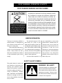
SAFETY ALERT SYMBOL
The symbol shown is used to call
your attention to instructions concerning your personal safety.
WARNING! BE ALERT!
Personnel operating or working around
Watch for this symbol; it points out
electric fans should read this manual.
important safety precautions. It
This manual must be delivered with the
means "ATTENTION", "WARN-
equipment to its owner. Failure to read
ING", "CAUTION", and "DANGER".
this manual and its safety instructions is
Read the message and be cau-
a misuse of the equipment.
tious to the possibility of personal
injury or death.
5
SAFETY ALERT DECALS
The GSI Group, Inc. recommends contacting your local power
company, and having a representative survey your installation so the
wiring is compatible with their system, and adequate power is supplied to your unit.
Safety decals should be read
and understood by all people in the
grain handling area. The rotating
blade, fire warning decals and voltage danger decal must be displayed
on the fan/heater can. The danger
decal, DC-552, should be present
on the inside bin door cover of the
two ring door, 24" porthole door
cover and the roof manway cover.
If a decal is damaged or is missing contact:
The GSI Group, Inc.
1004 E. Illinois St.
Assumption, IL 62510
217-226-4421
A free replacement will be sent to you.
6
LTD HEATER INSTALLATION
FUEL CONNECTION
Important! Do not use propane tanks which have previously
been used for ammonia unless they have been purged according to procedures of the National L. P. Association.
Be sure fuel supply system complies with all local codes
for L. P. gas installations.
PROPANE VAPOR MODELS
3. After installation is complete
2. Run proper size line (see speci-
check all connections for leaks.
fications) to pipe train on heater.
signed to run directly off of sup-
DO NOT USE FLAME FOR
Have a qualified gas service
ply tank or from a separate ex-
LEAK TESTING. (See above for
man inspect installation to be
ternal vaporizer.
other precautions.)
sure everything is installed ac-
1. Propane vapor models are de-
cording to local codes and ordi2. Run proper size line (see specifications) to pipe train on heater.
NATURAL GAS MODELS
nances.
1. Natural gas models are similar
3. After installation is complete
Have a qualified gas service
to vapor models, but have a
person inspect installation to be
larger orifice to accommodate
check all connections for leaks.
sure everything is installed ac-
lower pressure sometimes
DO NOT USE FLAME FOR
cording to local codes and ordi-
found with natural gas.
LEAK TESTING. (See above for
nances.
other precautions.)
7
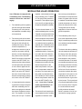
LTD HEATER INSTALLATION
INSTALLING THE LTD HEATER WITH LTD MOUNTING BRACKETS
THESE INSTRUCTIONS ARE
FOR HEATER INSTALLATION
ON FAN UNITS WITH 230V
MOTORS.
BE SURE POWER IS
DISCONNECTED AND LOCKED
IMPORTANT!
on
Note: Heater Directi
OUT BEFORE INSTALLATION!
FAILURE TO DO SO MAY CAUSE
SERIOUS INJURY OR DEATH.
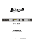
Figure 1: Make sure the LTD Heater is positioned in the right direction.
1. Place heater on the ground next
to the inlet of the centrifugal fan.
The LTD heater is designed to
mount upwind. Be sure airflow
decal is pointing towards the inlet of the fan.
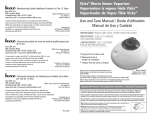
2. Bolt LTD mounting brackets to
each of the six holes in the
downstream angle ring of the
heater. Snug tighten bolts such
Figure 2: The six(6) mounting brackets positioned on the LTD Heater.
that they can still pivot with little
force applied. See chart for slots
six(6) bolts and bolt the remain-
to bolt through in bracket.
ing six(6) brackets to fan using
nuts removed. It may be neces-
Slot
Fan Inlet Bolt Circle
End
31" to 35"
Middle
Less than 31"
3. Pivot brackets so they are nearly
radial from center of heater.
Stand behind heater and deter
mine which bolts on fan inlet
best line up with the brackets.
Remove the nuts from those
8
sary to remount the fan grill
guard so mounting brackets will
seat properly. Slots to use for
fan mounting bolts are below.
Slot
Fan Inlet Bolt Circle
End
35"
Middle
31 3/4"
Inner
29"
Figure 3: The LTD Heater brackets
pivoted so they are radial from the
center of the heater.
LTD HEATER INSTALLATION
4. Lift heater and align paired
brackets as shown and insert
bolts in corresponding slots as
in table below. Be sure to place
washer provided between tap
and bracket. Tighten bolts snug
but loose enough to slide heater
in and out.
Slot
Fan HP
Heater
Fan
5
Middle
Middle
7.5
End
Middle
10
End
Middle
15
End
End
20
End
End
25
End
End
Figure 4: Heater aligned with paired brackets and bolts inserted.
5. Align mating bracket pairs so
that they are in a straight line.
Tighten bolts on fan and heater
rigid.
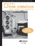
6. Make sure the heater stand off
dimension is correct for the fan
used. Refer to the table below.
Slide the heater to meet the
Figure 5: Align mating bracket pairs in a straight line.
IMPORTANT!
stand off dimension all around.
Tighten mating brackets rigid.
The heater should now be securely fastened to the fan. If not
tighten all loose connections.
Fan HP
Stand Off
5
5"
7.5
7"
10
7"
15
7 1/2"
20
8 1/2"
25
8 1/2"
Figure 6: Check the heater stand off distance, based on fan horsepower.
9
LTD HEATER INSTALLATION
Note: The optimum distance the
8. The LTD stand off bracket can
heater should stand away from the
increase the efficiency of the fan
mounted, connect gas lines as
fan inlet has been experimently de-
and heater dramatically com-
required per the installation re-
termined. If there are any ignition
pared to using an upwind
quirements.
problems, or flame quality is not as
mounting plate. Moreover, by
desired, move heater in or out, cali-
applying the heat to the air up-
brating heater to actual field condi-
wind, the air will be a constant
tions. Variation from table may be
temperature discharging into
required to adjust for grain depth,
the plenum resulting in more
fan performance and bin size.
uniform drying.
10
9. After heater is securely
LTD HEATER INSTALLATION
LTD HEATER ELECTRICAL INSTALLATION (230V FANS)
1. Connect power cord to fan control box.
IMPORTANT! HEATER MUST
trol (optional) in heater box as
BE INTERLOCKED WITH FAN
shown in Figure 1. IMPOR-
FOR SAFE OPERATION.
TANT! THERMOSTAT MUST
2. Make field connections of wires
in fan box as shown in Figure
BE INSTALLED FOR SAFE
3. Connect deluxe thermostat con-
OPERATION.
1.
Figure 7: 230 volt fan control box.
11
LTD HEATER INSTALLATION
LTD HEATER ELECTRICAL INSTALLATION (460V FANS)
1. Connect power cord to fan control box.
or .5KVA 460V to 110V transformer must be used to
trol (optional) as shown in Fig-
supply power for heater. IM-
ure 2. IMPORTANT! THERMO-
PORTANT! HEATER MUST
STAT MUST BE INSTALLED
wires in fan box as shown in
BE INTERLOCKED WITH
FOR SAFE OPERATION.
Figure 2. 110V power supply
FAN FOR SAFE OPERATION.
2. Make field connections of
Figure 8: 460 volt fan control box.
12
3. Connect deluxe thermostat con-
LTD HEATER INSTALLATION
AIRSTREAM SURFACE MOUNT HUMIDISTAT (EDS SYSTEMS ONLY)
1. The humidistat can be used to
3. The housing of the humidistat
directly control the operation of
has a perforated bottom allow-
junction with a temperature
a heater for drying, or with addi-
ing air to surround the sens-
sensing control device (thermo-
tional equipment, the operation
ing element. The perforated
stat), which senses the drying
of a fan for aeration.
bottom insures accurate sens-
air temperature. If the plenum air
ing of the (outside) humidity.
temperature exceeds the setting
The housing also incorporates
of the thermostat, the thermostat
humidity rise. If the humidistat
a vent hole at the top of one
opens and the heater shuts off.
is set at 50% relative humidity
side. This guards against heat
When the plenum temperature
and the humidity of the air sur-
build up in the box, changing
drops below the setting of the
rounding the sensing unit on the
the relative humidity and de-
thermostat, the thermostat
humidistat is greater than 50%
stroying the heat sensing abil-
closes and the heater turns on
relative humidity, the micro-
ity of the unit. Also, air is drawn
again. The thermostat is a safety
switch remains closed. When
through the perforated bottom
device keeping the grain tem-
the humidity drops below 50%
and across the sensing ele-
perature equal to the thermostat
relative humidity the micro-
ment of the humidistat. These
setting. Some grains are more
switch opens. Power then
design features insure accurate
sensitive to temperature. Qual-
ceases to travel through the hu-
sensing of relative humidity.
ity, germination and value are
2. The humidistat closes on a
midistat, simultaneously shutting off the heater. If the humi-
5. The humidistat is used in con-
lost due to high temperatures.
4. The humidistat should be
Grains used for seed, rice and
distat is used as an aeration
mounted with the back plate,
popcorn are adversely effected
control or fan control for natural
corner holes on a corrugation
by high temperatures.
air drying, additional equipment
hill. It should be positioned ap-
is required to control the fan
proximately three feet from the
power supply, so it runs when
ground or grade line as shown
the humidistat is open.
in the illustration.
13
LTD HEATER INSTALLATION
SURFACE MOUNT HUMIDISTAT (AS A HEATER CONTROL)
REDRAW
BOTH HUMIDISTAT AND THERMOSTAT MUST BE CLOSED FOR HEATER
OPERATION
REDRAW
14
LTD HEATER INSTALLATION
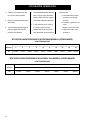
LOW TEMPERATURE HEATER SPECIFICATIONS
18"
All models
Inside diameter
Bolt circle diameter
Length
BTU rating
Weight
18.5/16"
19.7/16"
22"
400000
81
Vapor models
Maximum fuel flow (GPH)
Orifice
Modulating valve bypass orifice
Minimum operating pressure
Maximum operating pressure
Minimum line size
167
5/64"
Red
2
20
3/8"
Natural gas
models
Maximum fuel flow (CFH)
Orifice
Modulating valve bypass orifice
Minimum operating pressure
Maximum operating pressure
Minimum line size
421
9/64"
Yellow
1
7
1/2"
15
LTD HEATER OPERATION
1. Check to see if high limit con-
4. For prolonged shutdown close the
trol is in the down position.
2. Open fuel valves between tank
problems are:
tank or supply valve and allow
a. Humidistat and /or ther-
flame to burn until all the gas is
mostat is not set high
out of the line (the flame dies out).
enough.
and heater.
b. Pressure regulator is not
5. If any problems occur refer to
3. Turn the heater power switch to
open.
the service section of this
c. Supply valve is not open.
ON by toggling the ON/OFF
manual and follow the proce-
d. High limit button is not
switch to ON position.
dure described. Some common
pushed in.
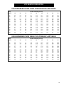
BTU'S PER GAUGE PRESSURE (PSI) PROPANE MODELS (APPROXIMATE)
LOW TEMPERATURE
Operating Pressure (PSI)
Diameter
2
4
6
8
10
12
14
16
18
20
18"
102900
145970
181870
208190
234510
253660
275200
294340
311090
335020
BTU'S PER GAUGE PRESSURE (PSI) NATURAL GAS MODELS (APPROXIMATE)
LOW TEMPERATURE
Operating Pressure (PSI)
16
Diameter
1
2
3
4
5
6
7
18"
144100
205200
250800
289100
322850
353860
383040
LTD HEATER OPERATION
MODULATING VALVE OPERATION
Your LTD heater is equipped with
regulator, run the heater and turn
tions as long as humidistat or
a modulating valve. The following
the modulating valve T-handle
thermostat do not shut down the
material should be read thor-
in. This gets full line pressure to
heater. A bypass orifice is used
oughly.
the burner. Then adjust regula-
to maintain a small flame when
tor to read 15 psi (depending on
outside temperature is near or
the plenum temperature needed).
above the set point of the valve.
1. The modulating valve regulates
gas flow through heater based
The bypass insures steady
on sensing unit in the plenum,
4. Turn the fan and heater on. To
and maintains a constant drying
set the modulating valve, turn the
air temperature.
T-handle out (counterclockwise)
until loose and wait a few min-
application of heat at minimum
gas flow operation.
6. The modulating valve may re-
2. The sensing bulb of the modu-
utes for the plenum temperature
quire minor adjustment periodi-
lating valve should be mounted
to equalize. When the tempera-
cally if a certain temperature rise
through the bin wall with the
ture under the bin has equalized,
over ambient (outside) tempera-
reading side top up. The bulb
gradually turn T-handle in (clock
ture is desired.
reacts to temperature. It
wise) about 1/2 turn. Wait until
changes the amount of gas (in
temperature under bin has
crease or decrease), burning
equalized as before. If tempera-
valve increases the efficiency of
warmer or cooler depending on
ture under bin is less than the
bin drying, check the gas pres-
the position of the valve SET
desired temperature, continue
sure of the unit in the morning
POINT. If the bulb is cooler than
turning T-handle in, increasing
and compare to the pressure
it was at the SET POINT, the
gas flow and waiting for plenum
read mid-afternoon. If the ambi-
bulb senses the cooler tempera-
temperature to equalize until the
ent (outside) temperature is sig-
ture and opens the valve further
desired temperature is the
nificantly greater later in the day
so more heat is applied to the
stable temperature of the ple-
(as normal), the gas pressure
drying air. If the bulb is warmer
num. If temperature under bin is
will be less. Since less heat is
than it was at the SET POINT,
the same 10 minutes after you
required to maintain the same
the valve closes further and re
last made any adjustments to
temperature in the plenum, the
duces the temperature until the
the T-handle you can be certain
modulating valve will have re-
air is at the valve SET POINT.
that the temperature under the
duced the amount of gas used
bin is the SET POINT of the
by the heater. This is preferred
3. It is important that the pressure
valve. 1 turn of the T-handle
to cycling the application of heat
regulator be set high enough to
equals approximately 7 de-
as is commonly done. The grain
allow the modulating valve to
grees F of temperature.
is not shocked and cooled
deliver enough gas to maintain
7. To observe how the modulating
quickly and then reheated,
the plenum temperature neces-
5. The valve will now keep the ple-
sary. The regulator is normally
num temperature at the set point
factory set at 15 psi. To set the
regardless of ambient condi-
which is a waste of fuel in conventional bin drying systems.
17
LTD HEATER OPERATION
The following tables are general
not tell us how fast the grain will lose
equilibrium with the drying air. The
values for equilibrium moisture con-
moisture to get to its equilibrium
following tables should only be used
tent. The equilibrium moisture con-
moisture content. Generally, drying
as a guide for management of grain
tent is the moisture content that the
air conditions with a lower equilib-
conditioning systems, possible de-
grain will eventually arrive at if ex-
rium moisture content are used to
viations may occur due to varieties
posed to specific air conditions for
increase the rate of moisture re-
and grain condition. (Values calcu-
a long enough period of time. The
moval. The drying process is then
lated from the Henderson-Thomp-
equilibrium moisture content does
stopped before the grain can reach
son equation.)
EQUILIBRIUM MOISTURE TABLE FOR SHELLED CORN % WET BASIS
Temp.
degrees
10
20
30
Relative Humidity (percent)
60
50
40
35
40
45
50
55
60
65
70
75
80
85
90
95
100
5.2
5.0
4.9
4.8
4.7
4.6
4.5
4.4
4.3
4.2
4.2
4.1
4.0
3.9
7.6
7.4
7.2
7.0
6.9
6.7
6.6
6.4
6.3
6.2
6.1
6.0
5.9
5.8
9.5
9.3
9.0
8.8
8.6
8.5
8.3
8.1
8.0
7.8
7.7
7.6
7.4
7.3
11.3
11.0
10.8
10.5
10.3
10.1
9.9
9.7
9.5
9.3
9.2
9.0
8.9
8.7
13.0
12.7
12.4
12.2
11.9
11.7
11.4
11.2
11.0
10.8
10.6
10.5
10.3
10.1
14.8
14.5
14.2
13.9
13.6
13.3
13.0
12.8
12.6
12.4
12.1
12.0
11.8
11.6
70
80
90
16.8
16.4
16.0
15.7
15.4
15.1
14.8
14.5
14.3
14.0
13.8
13.6
13.4
13.2
19.1
18.7
18.3
17.9
17.5
17.2
16.9
16.6
16.3
16.0
15.8
15.5
15.3
15.1
22.2
21.7
21.3
20.9
20.5
20.1
19.7
19.4
19.1
18.8
18.5
18.2
17.9
17.7
EQUILIBRIUM MOISTURE TABLE FOR ROUGH RICE % WET BASIS
Temp.
degrees
10
20
30
Relative Humidity (percent)
60
50
40
35
40
45
50
55
60
65
70
75
80
85
90
95
100
6.3
6.1
6.0
5.9
5.8
5.7
5.6
5.6
5.5
5.4
5.3
5.3
5.2
5.1
8.3
8.2
8.0
7.9
7.7
7.6
7.5
7.4
7.3
7.2
7.1
7.0
6.9
6.8
9.9
9.7
9.6
9.4
9.2
9.1
9.0
8.8
8.7
8.6
8.5
8.4
8.3
8.2
11.3
11.1
10.9
10.7
10.5
10.4
10.2
10.1
9.9
9.8
9.7
9.6
9.4
9.3
18
12.6
12.4
12.2
12.0
11.8
11.6
11.4
11.3
11.1
11.0
10.8
10.7
10.6
10.4
13.9
13.7
13.4
13.2
13.0
12.8
12.6
12.5
12.3
12.1
12.0
11.8
11.7
11.6
70
80
90
15.3
15.1
14.8
14.6
14.3
14.1
13.9
13.7
13.5
13.4
13.2
13.1
12.9
12.8
16.9
16.6
16.4
16.1
15.9
15.6
15.4
15.2
15.0
14.8
14.6
14.5
14.3
14.1
19.1
18.8
18.5
18.2
17.9
17.7
17.4
17.2
17.0
16.8
16.6
16.4
16.2
16.0
LTD HEATER OPERATION
EQUILIBRIUM MOISTURE TABLE FOR SORGHUM % WET BASIS
Temp.
degrees
10
20
30
Relative Humidity (percent)
60
50
40
35
40
45
50
55
60
65
70
75
80
85
90
95
100
6.2
6.1
6.1
6.0
6.0
5.9
5.9
5.8
5.8
5.7
5.7
5.7
5.6
5.6
8.2
8.1
8.1
8.0
7.9
7.9
7.8
7.7
7.7
7.6
7.6
7.5
7.5
7.4
9.8
9.7
9.6
9.5
9.4
9.4
9.3
9.2
9.1
9.1
9.0
8.9
8.9
8.8
11.1
11.0
10.9
10.8
10.7
10.7
10.6
10.5
10.4
10.3
10.3
10.2
10.1
10.1
12.4
12.3
12.2
12.1
12.0
11.9
11.8
11.7
11.6
11.5
11.5
11.4
11.3
11.2
13.7
13.5
13.4
13.3
13.2
13.1
13.0
12.9
12.8
12.8
12.7
12.6
12.5
12.4
70
80
90
15.0
14.9
14.8
14.7
14.5
14.4
14.3
14.2
14.1
14.0
13.9
13.8
13.8
13.7
16.6
16.4
16.3
16.2
16.1
15.9
15.8
15.7
15.6
15.5
15.4
15.3
15.2
15.1
18.7
18.5
18.4
18.2
18.1
18.0
17.9
17.7
17.6
17.5
17.4
17.3
17.2
17.1
EQUILIBRIUM MOISTURE TABLE FOR SOYBEANS % WET BASIS
Temp.
degrees
10
20
30
Relative Humidity (percent)
60
50
40
35
40
45
50
55
60
65
70
75
80
85
90
95
100
3.0
2.9
2.8
2.7
2.6
2.5
2.4
2.3
2.3
2.2
2.1
2.1
2.0
2.0
5.1
4.9
4.7
4.5
4.4
4.2
4.1
4.0
3.8
3.7
3.6
3.5
3.5
3.4
7.1
6.8
6.5
6.3
6.1
5.9
5.7
5.5
5.3
5.2
5.1
4.9
4.8
4.7
9.0
8.6
8.3
8.0
7.7
7.5
7.3
7.0
6.8
6.7
6.5
6.3
6.2
6.0
11.0
10.6
10.2
9.8
9.5
9.2
8.9
8.7
8.4
8.2
8.0
7.8
7.6
7.4
13.2
12.7
12.2
11.8
11.4
11.1
10.7
10.4
10.1
9.9
9.6
9.4
9.2
8.9
70
80
90
15.6
15.1
14.5
14.1
13.6
13.2
12.8
12.5
12.1
11.8
11.5
11.2
11.0
10.7
18.7
18.0
17.4
16.8
16.3
15.8
15.4
15.0
14.6
14.2
13.9
13.5
13.2
12.9
23.0
22.2
21.5
20.8
20.2
19.7
19.1
18.6
18.2
17.7
17.3
16.9
16.5
16.2
19
LTD HEATER OPERATION
EQUILIBRIUM MOISTURE TABLE FOR WHEAT (SOFT) % WET BASIS
Temp.
degrees
10
20
30
Relative Humidity (percent)
60
50
40
35
40
45
50
55
60
65
70
75
80
85
90
95
100
6.3
6.2
6.1
6.0
5.9
5.9
5.8
5.7
5.7
5.6
5.5
5.5
5.4
5.4
8.3
8.1
8.0
7.9
7.8
7.7
7.6
7.5
7.4
7.4
7.3
7.2
7.1
7.1
9.8
9.6
9.5
9.4
9.2
9.1
9.0
8.9
8.8
8.7
8.6
8.5
8.4
8.4
11.1
10.9
10.8
10.6
10.5
10.4
10.2
10.1
10.0
9.9
9.8
9.7
9.6
9.5
20
12.3
12.1
12.0
11.8
11.7
11.5
11.4
11.3
11.1
11.0
10.9
10.8
10.7
10.6
13.5
13.3
13.2
13.0
12.8
12.7
12.5
12.4
12.3
12.1
12.0
11.9
11.8
11.7
70
80
90
14.8
14.6
14.4
14.2
14.1
13.9
13.7
13.6
13.4
13.3
13.2
13.0
12.9
12.8
16.3
16.1
15.9
15.7
15.5
15.3
15.2
15.0
14.8
14.7
14.5
14.4
14.3
14.1
18.3
18.1
17.9
17.6
17.4
17.2
17.0
16.9
16.7
16.5
16.4
16.2
16.1
15.9
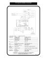
LTD HEATER WIRING DIAGRAM
21
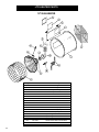
LTD HEATER PARTS
18" GAS HEATER
Key
1
2
3
4
5
6
7
8
9
10
11
12
13
14
NS
NS
NS
15
16
22
Part Number
HF-6785
HH-3933
HH-4410
HF-7073
HF-6062-18
HF-7380
HF-7379
TFH-2046
HF-983
HF-978
HH-4416
HH-4421
F-953
HH-1650
HF-1810
HF-7260
HF-7262
THH-4179
CD-0187
Description
18" Heater Housing
18" Burner Casting
18" Lo-Temp Flame Spreader
18" Lo-Temp Flame Diverter
18" Access Panel
Plastic View Window
Access Panel Cover Plate
Access Panel Latch
18/24" Burner Collector
18/24/26" Burner Collector Plate
Drum Grill Guard (LTD)
Stand-Off Bracket (LTD)
18" Grill Guard (LTD)
Spark Plug
Spark Plug Nut
18-28" Heater Spark Plug Wire
18-28" Heater Flame Probe Wire
Flame Sensor
Flame Sensor Bracket
LTD HEATER PARTS
AXIAL PROPANE VAPOR & NATURAL GAS PIPETRAIN
Key
1
2
3
4
5
6
7
8
8
9
Part Number
HH-1077
HH-3670
TFC-0032
HH-2029
HH-2984
S-3853
HH-1083
CD-0149
HF-7085
HH-2653
Description
1/2" regulator
1/2" x 2-1/2" nipple
1/2" solenoid
1/2" x 1-1/2" nipple
1/4" gauge 30PSI
1/2" x 1/4" x 1/2" tee
18/24/28" Orifice pipe
5/64" Orifice plug (propane)
9/64" Orifice plug (natural gas)
Modulating valve
23
LTD HEATER PARTS
CONTROL BOX PARTS
Key
1
2
3
4
5
6
7
8
9
10
24
Part Number
F-942
HH-1487
HF-7318
HH-1092
FH-4429-1
HF-7211
HF-7046
DC-1166
TFH-2021
HH-1442
Description
Control Box Lid
Ignition Transformer
Deluxe Control Board
Housing Hi-Limit
Latch
Snap Track
18" Control Box Housing
Control Box Decal
110V Red Light
Toggle Switch
25
AIRSTREAM GRAIN CONDITIONING SYSTEMS
1004 E. Illinois St.
Assumption, IL 62510
phone 217-226-4421
fax 217-226-4498
October 1997
26