1
F&eIT Series
Monitoring & Control Server
SVR-MMF2(FIT)
Hardware Setup Guide
CONTEC CO.,LTD.
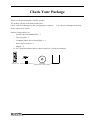
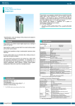
Check Your Package
Thank you for purchasing the CONTEC product.
The product consists of the items listed below.
Check, with the following list, that your package is complete.
items, contact your retailer.
If you discover damaged or missing
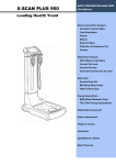
Product Configuration List
-
System unit [SVR-MMF2(FIT)] ...1
-
First step guide ...1
-
CD-ROM [F&eIT Series Setup Disk]*1 ...1
-
Power input connector ...1
-
Magnet ...2
*1 The CD-ROM contains various software and User’s Guide (this manual)
x2
Magnet
ACT
LINK
SVR-MMF2
System unit Power input connector
SVR-MMF2(FIT)
CD-ROM
First step guide
[F&eIT Series Setup Disk]
i
Copyright
Copyright 2005 CONTEC CO., LTD.
ALL RIGHTS RESERVED.
No part of this document may be copied or reproduced in any form by any means without prior written
consent of CONTEC CO., LTD.
CONTEC CO., LTD. makes no commitment to update or keep current the information contained in
this document.
The information in this document is subject to change without notice.
All relevant issues have been considered in the preparation of this document.
Should you notice an
omission or any questionable item in this document, please feel free to notify CONTEC CO., LTD.
Regardless of the foregoing statement, CONTEC assumes no responsibility for any errors that may
appear in this document or for results obtained by the user as a result of using this product.
Trademarks
F&eIT is a registered trademark of CONTEC CO., LTD. Other company and product names
mentioned herein are generally trademarks or registered trademarks of their respective owners
ii
SVR-MMF2(FIT)
Table of Contents
Check Your package ............................................................................................................................... i
Copyright .................................................................................................................................................ii
Trademarks ..............................................................................................................................................ii
Table of Contents ...................................................................................................................................iii
1.
Before Using the Product
1
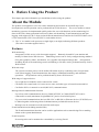
About the Module.................................................................................................................................... 1
Features............................................................................................................................................. 1
System Configuration Image ........................................................................................................... 3
Example of System Configuration .................................................................................................. 4
Customer Support.................................................................................................................................... 5
Web Site ........................................................................................................................................... 5
Limited One-Year Warranty ................................................................................................................... 5
How to Obtain Service............................................................................................................................ 5
Liability ................................................................................................................................................... 5
Safety Precautions ................................................................................................................................... 6
Safety Information ........................................................................................................................... 6
Handling Precautions ....................................................................................................................... 6
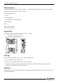
Environment ..................................................................................................................................... 8
Inspection ......................................................................................................................................... 8
Storage.............................................................................................................................................. 8
Disposal ............................................................................................................................................ 8
2.
Module Nomenclature and Settings
9
Nomenclature of Module Components .................................................................................................. 9
Function of the Various Components................................................................................................... 11
CompactFlash Slot ......................................................................................................................... 11
RUN LED....................................................................................................................................... 11
STATUS LED ................................................................................................................................ 11
SHUT DOWN ................................................................................................................................ 11
SW1 ................................................................................................................................................ 11
SW2 ................................................................................................................................................ 12
Ethernet........................................................................................................................................... 12
POWER .......................................................................................................................................... 13
3.
Hardware Setup
15
Getting Started....................................................................................................................................... 15
Mounting the Module............................................................................................................................ 16
Mounting / removing on a DIN Rail ............................................................................................. 19
SVR-MMF2(FIT)
iii
Connection Method ...............................................................................................................................22
Supplying the Power to the Controller Module.............................................................................22
4.
System Setup
25
Summary Manual...................................................................................................................................25
5.
Setup Troubleshooting
27
6.
Appendix
29
System Reference ..................................................................................................................................29
Product Specifications....................................................................................................................29
External dimensions .......................................................................................................................31
iv
SVR-MMF2(FIT)
1. Before Using the Product
1. Before Using the Product
This chapter provides information you should know before using the product.
About the Module
The product is an appliance server for remote monitoring and control on which all steps from
development to actual operation can be performed from a Web browser. The server enables a remote
monitoring system to be implemented quickly and at low cost with functions such as monitoring I/O
data via the Web, alarm generation based on I/O data, task branching, E-mail transmission, and data
logging, with support for PLCs from various different manufacturers and for the CONTEC F&eIT series
of I/O control units (CPU-CAxx(FIT)GY*1) and similar devices.
*1 The "x" in a model code represents a single digit (or no digit) indicating different products.
(The same convention applies below).
Features
Web monitoring
Incorporates a Web server (with Java applet support). Remotely located PCs can monitor and
modify I/O data from a Web browser. Monitoring screens can be freely configured using standard
GUI parts (graphics, sliders, and buttons, etc.) together with imported image data. All operation,
including layout of the monitoring screens and linking to I/O data, can be performed entirely from a
Web browser.
Web task script
The system execution process can be defined flowchart-style by combining icons for operations
such as data logging, E-mail transmission, data output, conditional branching, and arithmetic
operations. All operations can be performed entirely from a Web browser.
Wide range of support devices
-
Up to eight device modules can be connected in a stack.
-
Can link to I/O control units, I/O Assist server units, and other types of network-connected I/O.
-
Can link to PLCs via network or serial (RS-232C) communications.
Message-based communication function
-
Up to four serial communications devices (COM-2(FIT)GY or COM-1PD(FIT)GY) can be
connected in a stack (maximum of eight RS0232C ports or four RS-422 ports).
-
Up to ten serial communications devices (RS-232C or RS-422) or Ethernet devices (TCP/UDP) can
be linked together and message-based communications performed between devices.
-
Messages can be sent and received from Web task scripts.
E-mail transmission (including attached files)
The E-mail transmission function can be used for applications such as transferring files or sending
alarms to the system administrator.
E-mail reception
Processing tasks can be monitored or controlled by receiving E-mail.
SVR-MMF2(FIT)
1
1. Before Using the Product
PPP server dialup connections
A PPP server function enables connections to an external host to be established via a telephone line
for maintenance, data transfer, and similar. Also the dialup function enables the internet connections
from the SVR-MMF2(FIT) by using telephon lines.
SNMP agent
Supports the SNMP protocol. Centralized control can be performed using CONTEC's "SNMPc"
or other network administration software.
Differences from the SVR-MMF(FIT)GY
The SVR-MMF2(FIT) supports the use of messaging in Web task scripts and Web monitoring.
Backups of Web monitoring and Web task scripts created on the SVR-MMF(FIT)GY can be used
on the SVR-MMF2(FIT) .
Table 1.1.
Differences from the SVR-MMF(FIT)GY
SVR-MMF(FIT)GY
SVR-MMF2(FIT)
CPU
MachZ(ZF Micro Devices)
Memory
64MBytes
64MBytes
CRT/IF
15 pin HD-SUB connector
-
Serial port on main unit
1
-
USB
2
-
Keyboard / mouse
1
-
Remarks
SH-4 240MHz
120MHz
CF(Compact frash)
Size
64MBytes
128MBytes
Data acquisition area
32MBytes
64MBytes
(Includes image files used for
1
4
COM-2(FIT)GY and
monitoring)
Number of serial devices
able to be connected in a
COM-1PD(FIT)GY can be
stack
Current consumption
External dimension (mm)
Weight
2
connected in a stack.
5VDC±5%
1.5A
52.4(W) x 64.7(D) x 94.0(H)
5VDC±5%
0.5A
25.2(W) x 64.7(D) x 94.0(H)
No protrusion
No protrusion
180g
100g
SVR-MMF2(FIT)
1. Before Using the Product
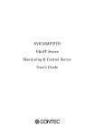
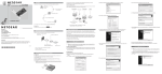
System Configuration Image
Multiple I/O controller units and the monitoring & controlling server can be installed on the same
network. When connected to the monitoring & controlling server, the host controller can read and
write signals from and to the devices that are connected to the subordinate I/O controller units.
Internet
Monitoring &
control server
I/O Assist Server Unit
Local terminal
Office terminal
HUB
Router
A CT
LINK
SVR-MMF2
I/O Controller Unit
Device
I/O Controller Unit
Device
I/O Controller Unit
Device
Device
Figure 1.1. System Configuration Image
Explanation of names
-
Monitoring & control server :
This refers to the product SVR-MMF2(FIT) .
Data can be collected from I/O Assist Servers and I/O controllers connected to the network as well
as from connected device modules.
The collected data can be displayed graphically by the monitoring function. Also, the internal
programming function allows monitoring to be customized easily to suit the application by, for
example, outputting alarms when upper or lower limits are exceeded or sending notification at fixed
time intervals.
The collected data can be stored on the unit’s CompactFlash card and sent to other network hosts
using E-mail or FTP.
-
I/O Assist Server Unit :
This refers to the product SVR-IOAx(FIT)GY.
The I/O Assist Server Unit supports the management function that enables it to collect data from,
and set data to, I/O Controller Units that belong to the same group as the Group ID that is set by
using the Group ID switches of the SVR-IOA(FIT) ("Assist Server"), which is a CONTEC product.
Group IDs can be set in a range of 0 - 7.
By connecting local terminals and office terminals by means of a Web browser, it is possible to
monitor the status of the devices that are connected to an I/O Controller Unit.
SVR-MMF2(FIT)
3
1. Before Using the Product
-
I/O Controller Unit :
The I/O Controller Unit is a general term that refers to any combination of this product,
the CPU-CAxx(FIT)GY, with device modules. Each device contains a Group ID SW and a Unit
ID SW; these switches must be set so that they are unique within the network.
The I/O Controller Unit transmits data collected from the devices to the I/O Assist Server Unit that
bears a specified Group ID.
Group IDs can be set in a range of 0 - 8, whereas Unit IDs are set in a range of 0 - 7.
When the Group ID is set to 8, no data is transmitted to the I/O Assist Server; instead, controls can
be performed directly from a terminal to the I/O Controller Unit.
The following device modules are available:
an 8-point digital input, an 8-point digital output module
(DIO-8/8(FIT)GY), a 16-point digital input module (DI-16(FIT)GY), a 16-point digital output
module (DO-16(FIT)GY), an 8-point input analog/digital converter module (ADI12-8(FIT)GY), a
4-point output digital/analog converter module (DAI12-4(FIT)GY), and a 2-point input counter
module (CNT24-2(FIT)GY).
Further details on this topic may be found in the respective device module manuals.
-
HUB :
This is a line concentration device that is used when a LAN is constructed using twisted-pair cables.
The F&eIT series includes an 8-port switching HUB unit
(SH-8008(FIT)GY) that is equipped with a DIN rail mounting mechanism.
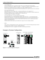
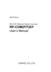
Example of System Configuration
SVR-MMF2(FIT)
POW-DD10GY
COM-2(FIT)GY DIO-8/8(FIT)GY
ADI12-8(FIT)GY
Nwtwork
ACT
LINK
POW-DD10
SVR-MMF2
COM-2
ADI12-8
DIO-8/8
Figure 1.2. System Configuration Diagram
4
SVR-MMF2(FIT)
1. Before Using the Product
Customer Support
CONTEC provides the following support services for you to use CONTEC products more efficiently
and comfortably.
Web Site
Japanese
English
Chinese
http://www.contec.co.jp/
http://www.contec.com/
http://www.contec.com.cn/
Latest product information
CONTEC provides up-to-date information on products.
CONTEC also provides product manuals and various technical documents in the PDF.
Free download
You can download updated driver software and differential files as well as sample programs available in
several languages.
Note!
For product information
Contact your retailer if you have any technical question about a CONTEC product or need its price,
delivery time, or estimate information.
Limited One-Year Warranty
CONTEC F&eIT products are warranted by CONTEC CO., LTD. to be free from defects in material
and workmanship for up to one year from the date of purchase by the original purchaser.
Repair will be free of charge only when this device is returned freight prepaid with a copy of the
original invoice and a Return Merchandise Authorization to the distributor or the CONTEC group office,
from which it was purchased.
This warranty is not applicable for scratches or normal wear, but only for the electronic circuitry and
original products. The warranty is not applicable if the device has been tampered with or damaged
through abuse, mistreatment, neglect, or unreasonable use, or if the original invoice is not included, in
which case repairs will be considered beyond the warranty policy.
How to Obtain Service
For replacement or repair, return the device freight prepaid, with a copy of the original invoice. Please
obtain a Return Merchandise Authorization number (RMA) from the CONTEC group office where you
purchased before returning any product.
*
No product will be accepted by CONTEC group without the RMA number.
Liability
The obligation of the warrantor is solely to repair or replace the product. In no event will the warrantor
be liable for any incidental or consequential damages due to such defect or consequences that arise from
inexperienced usage, misuse, or malfunction of this device.
SVR-MMF2(FIT)
5
1. Before Using the Product
Safety Precautions
Understand the following definitions and precautions to use the product safely.
Safety Information
This document provides safety information using the following symbols to prevent accidents resulting in
injury or death and the destruction of equipment and resources. Understand the meanings of these
labels to operate the equipment safely.
DANGER
DANGER indicates an imminently hazardous situation which, if not avoided, will
result in death or serious injury.
WARNING
WARNING indicates a potentially hazardous situation which, if not avoided, could
result in death or serious injury.
CAUTION
CAUTION indicates a potentially hazardous situation which, if not avoided, may
result in minor or moderate injury or in property damage.
Handling Precautions
CAUTION
-
Do not use or store the equipment in a hot or cold place, or a place that is subject to severe
temperature changes.
Examples:
- Under direct sunlight
- Near a heat source
-
Do not use or store the equipment in a place that is subject to extreme humidity or dust. It will be
extremely dangerous to use the equipment when its interior is contaminated with water or liquid, or
conducting debris. When using the equipment in an environment that is subject to water or
conducting debris, consideration should be given to the installation of a control panel with a
structure that keeps dust out.
-
Do not use or store the equipment in a place that is subject to shock or vibrations.
-
Do not use or store the product near equipment generating a strong magnetic field or radio waves.
-
Do not use or store the equipment in air with diffused chemicals or in an environment in which the
equipment can come into contact with chemicals.
-
When attaching or detaching a module or a connector, please be sure that the power cable for the
system is unplugged from the outlet.
-
Do not modify the unit. CONTEC will bear no responsibility for any problems, etc., resulting
from modifying this unit.
-
If you notice any malfunction or abnormal conditions (such or a strange odor or overheating),
please unplug the power cord and consult your retailer.
-
Use an earthed shielded cable to connection to peripheral devices.
-
To clean the unit, gently wipe it with a soft cloth soaked with water or a neutral detergent. Do not
use benzene, a thinner, or other volatile solvents as they can cause the coating to discolor or peel
off.
6
SVR-MMF2(FIT)
1. Before Using the Product
-
Life of the components
Battery …A primary lithium battery is used to back up the internal clock/calendar and the
CMOS RAM. When the power is not drawn and the battery is stored at 25°C,
it will last over 10 years.
*
Replacement of expendables is handled as a repair (there will be a charge).
FCC PART 15 Class A Notice
NOTE
This equipment has been tested and found to comply with the limits for a Class A digital device,
pursuant to part 15 of the FCC Rules. These limits are designed to provide reasonable protection
against harmful interference when the equipment is operated in commercial environment.
This equipment generates, uses, and can radiate radio frequency energy and, if not installed and
used in accordance with the instruction manual, may cause harmful interference to radio
communications. Operation of this equipment in a residential area is likely to cause harmful
interference at his own expense.
WARNING TO USER
Change or modifications not expressly approved the manufacturer can void the user's authority to
operate this equipment.
SVR-MMF2(FIT)
7
1. Before Using the Product
Environment
Use this product in the following environment.
may overheat, malfunction, or cause a failure.
If used in an unauthorized environment, the module
Operating temperature
0 - 50°C
Operating humidity
10 - 90%RH (No condensation)
Corrosive gases
None
Floating dust particles
Not to be excessive
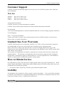
Inspection
Inspect the product periodically as follows to use it safely.
* The ventilation slits are not covered,
and neither dust nor alien substance is
attached to the ventilation slits
ACT
LINK
SVR-MMF2
Storage
When storing this product, keep it in its original packing form.
(1) Put the product in the storage bag.
(2) Wrap it in the packing material, then put it in the box.
(3) Store the package at room temperature at a place free from direct sunlight, moisture, shock,
vibration, magnetism, and static electricity.
Disposal
When disposing of the product, follow the disposal procedures stipulated under the relevant laws and
municipal ordinances.
8
SVR-MMF2(FIT)
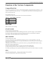
2. Module Nomenclature and Settings
2. Module Nomenclature and Settings
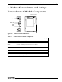
Nomenclature of Module Components
Expansion bus
5VDC Input
RESET SW
SHUT DOWN
SW1
SW2
10/100BASE-TX
ACT
LINK
SVR-MMF2
Figure 2.1. Names of module components
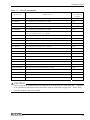
Table 2.1.
Nomenclature of Module Components
Name
Function
Referring pages
CompactFlash
CompactFlash inserting connector(TYPE 2 True IDE)
11
RUN LED
Status display LED
11
STATUS LED
Status display LED
11
RESET
Reset the CPU(Only used in the case of a problem)
SHUTDOWN
SHUTDOWN SW
11
SW1
User SW1
11
SW2
User SW2
12
10/100BASE-TX
RJ-45 connector
12
5VDC
Power connector(MC1,5/3-G-3,5 PHOENIX CONTACT)
13
Expansion bus
Connector for connecting the F&eIT Series
(0.6mm pitch 80 pin(FX-8C Series HIROSE))
SVR-MMF2(FIT)
-
-
9
2. Module Nomenclature and Settings
LED and Setup SW
Table 2.2.
Name
LED
USER SW
LAN LED
*1
LED and Setup SW
Function
Setup & display contents
RUN LED
ON : Abnormal condition
Flashing : Normal operating
OFF : Abnormal condition
STATUS LED
OFF : Normal operating
ON : System shutdown complete
Flashing : System shutdown in progress
RESET button
Hardware reset
SHUT DOWN
System shutdown button : The RUN LED and STATUS LED
blink when a system shutdown occurs.
SW1
Up : System boot mode(factory default setting)
Down : Not used(for factory testing)
SW2
Up : Initialization mode (Restore factory default settings) *1
Down : Normal mode(factory default setting)
ACT
OFF : No communications in progress
ON : Communications in progress
LINK
OFF : Not connected
ON : LAN connection
Initialization mode (This setting causes all settings to return to their factory defaults when the power is turned on.
The RUN LED and STATUS LED both blink.
The LEDs stop blinking when initialization completes.
Turn off the power and set SW2 back to normal boot mode before rebooting.)
Default IP address : 10.1.1.1 Default subnet mask : 255.0.0.0
Default user name : mmf
10
Default password : mmf
SVR-MMF2(FIT)
2. Module Nomenclature and Settings
Function of the Various Components
CompactFlash Slot
The system is equipped with a slot for CompactFlash-compliant CompactFlash cards [TYPE II x 1 size],
which is available for memory cards only. A CompactFlash card loaded with monitoring and control
tools is inserted in the unit.
Power supply for the card
Available card voltages and current values for each slot are listed below:
Table 2.3.
Voltage
Power Supply for the Card
Current(Max.)
+5V
500mA/Slot
+3.3V
Not supplied
+12V
Not supplied
RUN LED
Blinks while the unit is running.
STATUS LED
Turned off during normal operation.
The RUN LED and STATUS LED start blinking when SW1 is pressed to trigger a system shutdown.
The STATUS LED stops blinking and remains illuminated after the system shutdown completes.
Wait until the LED stops blinking before turning off the power.
SHUT DOWN
Used to shutdown the system.
If you have changed the setup, modified the monitoring screens or task programming, or the task
programming is storing data on the CF (compact flash disk), do not turn off the power until writing the
data to the CF has finished.
Although you also can shutdown the system from a browser, pressing SHUTDOWN finishes writing
data to the CF before shutting down.
If data is not being written to the CF, it is safe to just turn off the system power.
The RUN LED and STATUS LED start blinking when you press SHUTDOWN.
The LEDs stop blinking once the system has shutdown and the power has turned off (about 10 seconds).
SW1
Selects the system boot mode. Always set this switch to the up position.
The lower switch position is only used in factory testing.
SVR-MMF2(FIT)
11
2. Module Nomenclature and Settings
SW2
Selects the system operation mode. Always set this switch to the down position.
You can restore the default factory settings by setting SW2 to the up position and booting the system,
for example if you have forgotten the IP address or password of the unit.
The RUN LED and STATUS LED start blinking. The STATUS LED stops blinking and remains
illuminated when the system has been set back to the default factory settings. Turn off the power and
then set the switch back to the lower position.
Ethernet
SVR-MMF2(FIT) is equipped with a Fast-Ethernet card.
- Network mode:
100BASE-TX/10BASE-T
- Transmission rate * :
100M/10M bps
- Max. network path length:
100m/segment
- Controller:
DP83815(National Semiconductor)
* Operation at 100 Mbps requires a Category 5 cable.
Table 2.4.
Ethernet connector
Connector type
RJ-45
1
10/100M
ACT
LINK
8
Pin No.
Signal name
Meaning
1
TD+
Transmitted data (+)
2
TD-
Transmitted data (-)
3
RD+
Received data (+)
4
N.C.
Not connected
5
N.C.
Not connected
6
RD-
Received data (+)
7
N.C.
Not connected
8
N.C.
Not connected
Network status display LED :
LINK
ACT
12
: Illuminates when a valid connection is present.
: Turns off when no communications in progress.
progress.
Illuminates when communications in
SVR-MMF2(FIT)
2. Module Nomenclature and Settings
POWER
This is a power supply connector
-
Power supply :
Table 2.5.
5.0V±5%
Power connector
Connector type
MC1,5/3-G-3,5(PHOENIX CONTACT)
Vi+
5VDC ViFG
Pin No.
Signal name
Meaning
Vi+
Power supply (5V)
2
Vi-
Power supply(GND)
3
FG
1
Frame ground
Available plug (bundled) : MC1,5/3-ST-3,5(PHOENIX CONTACT)
SVR-MMF2(FIT)
13
2. Module Nomenclature and Settings
14
SVR-MMF2(FIT)
3. Hardware Setup
3. Hardware Setup
Getting Started
Follow the following procedures to set up the SVR-MMF2(FIT) :
STEP1
Connecting the F&eIT series module
By referring to this chapter connects the F&eIT series module to the SVR-MMF2(FIT) .
When using the SVR-MMF2(FIT) on a standalone basis, go to STEP2.
STEP2
Set switches
Set SW1 to the up position(default setting : up).
Set SW2 to the down position(default setting : down).
STEP3
Connecting the cables
Connect the LAN cable and any modem or other external device cables to
the SVR-MMF2(FIT) .
STEP4
Turning on the power
After re-checking that STEPS 1 - 2 have been correctly performed, turn on the power. If
something goes wrong after the power is turned on, immediately turn off the power and
make sure that the system is correctly set up.
SVR-MMF2(FIT)
15
3. Hardware Setup
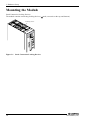
Mounting the Module
Stack Connection Locking Devices
The module contains connecting locking devices (
mark, two units at the top and bottom).
Locking device
Figure 3.1. Stack Connection Locking Devices
16
SVR-MMF2(FIT)
3. Hardware Setup
How the stack connection locking device works
- Locking
Push the pawl of the locking device with a tool that has a slender tip downward from above to open
the spring for the locking device (the groove moves toward you).
Locking device
Figure 3.2. Operation of Lock for Stack Connections(Locking)
- Unlocking
Push the groove of the locking device with a tool that has a slender tip in the direction of the arrow
until the device is locked.
Locking device
Figure 3.3. Operation of Lock for Stack Connections (Unlocking)
SVR-MMF2(FIT)
17
3. Hardware Setup
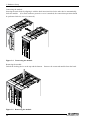
Connecting the module
Inserting the stack hook by aligning it with the hook insertion inlet for the other device automatically
locks the module. (If a stack connector protective cover is attached, the connection operation should
be performed after the cover is removed.)
Figure 3.4. Connecting the module
Removing the module
Unlock the locking device at the top and the bottom.
Remove the connected module from the hook.
Figure 3.5. Removing the module
18
SVR-MMF2(FIT)
3. Hardware Setup
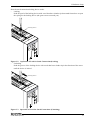
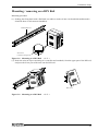
Mounting / removing on a DIN Rail
Mounting procedure
(1) Pushing the fixing hook with a flat-blade screwdriver renders it into a lock-enabled condition (this
should be done on all connected modules).
35mm DIN rail
Press here
to lift the fixing hook.
Figure 3.6. Mounting on a DIN Rail < 1 / 3 >
(2) Hook the unit (an object consisting of a controller and a module) from the upper part of the DIN rail,
and press the lower part of the unit onto the DIN rail.
Side view
Figure 3.6. Mounting on a DIN Rail
SVR-MMF2(FIT)
<2/3>
19
3. Hardware Setup
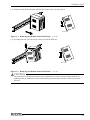
(3) The fixing hook is automatically locked, and the module can be mounted in one-touch.
Side view
Fixing hook
Figure 3.6. Mounting on a DIN Rail
<3/3>
Removal procedure
(1) Lower the fixing hook for the unit to unlock it.
connected modules.)
(This operation should be performed on all
35mmDIN rail
Figure 3.7. Removing the Module from the DIN Rail
20
<1/3>
SVR-MMF2(FIT)
3. Hardware Setup
(2) With the fixing hook unlocked, pull the lower part of the unit toward you.
Side view
Figure 3.7. Removing the Module from the DIN Rail
<2/3>
(3) By lifting the unit, you can easily remove it from the DIN rail.
Side view
Figure 3.7. Removing the Module from the DIN Rail
<3/3>
CAUTION
Any operation involving the disconnection of modules in a unit (in which multiple modules are
connected) that is attached to a DIN rail should be performed after the unit is removed from the
DIN rail.
SVR-MMF2(FIT)
21
3. Hardware Setup
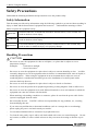
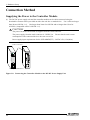
Connection Method
Supplying the Power to the Controller Module
(1) The DC-DC power supply unit and the controller module can be cable-connected using the
detachable connector that is provided on either the unit face or module face. Use a cable no longer
than 50cm (AWG24 - 16). (No longer than 20cm for AWG28 and no longer than 35cm for
AWG26). (compatible cables: AWG28 - 16).
CAUTION
The power for the device module is supplied from the stack connector.
The power supply from the stack connector is 5.0VDC/3A.
consumption of the connected devices does not exceed 3A.
Ensure that the total current
Power supply input requirements for the SVR-MMF2(FIT) : 5.0VDC±5%, 0.5A(Max.)
Cable connection
ACT
LINK
POW-DD10
SVR-MMF2
(Example : POW-DD10)
Figure 3.8. Connecting the Controller Module to the DC-DC Power Supply Unit
22
SVR-MMF2(FIT)
3. Hardware Setup
Table 3.1.
Current consumption
Product type
Module species
Current
consumption
(5.0VDC)
DIO-8/8(FIT)GY
Isolated Digital Input/Output Module (12 - 24VDC)
0.15A
DI-16(FIT)GY
Isolated Digital Input Module (12 - 24VDC)
0.15A
DO-16(FIT)GY
Isolated Digital Output Module (12 - 48VDC)
0.15A
DIO-8/8H(FIT)GY
Isolated Digital Input/Output Module (36 - 48VDC)
0.15A
DI-16H(FIT)GY
Isolated Digital Input Module (36 - 48VDC)
0.15A
DIO-4/4(FIT)GY
Isolated Digital Input/Output Module
(input : 12 - 24VDC, output : 12 - 48VDC)
0.15A
DI-8(FIT)GY
Isolated Digital Input Module (12 - 24VDC)
0.15A
DO-8(FIT)GY
Isolated Digital Output Module (12 - 48VDC)
0.15A
DO-8D(FIT)GY
Un-isolated Bi-Directional Digital Input/Output Module
0.15A
DIO-16/16(FIT)GY
Isolated Digital Input/Output Module (12 - 24VDC)
0.15A
DI-32(FIT)GY
Isolated Digital Input Module (12 - 24VDC)
0.15A
DO-32(FIT)GY
Isolated Digital Output Module (12 - 48VDC)
0.15A
AD12-8(FIT)GY
Isolated Analog Input Module
0.35A
AD16-4(FIT)GY
Isolated High-Resolution Analog Input Module
0.30A
DAI12-4(FIT)GY
Isolated Analog Output Module
0.40A
DAI16-4(FIT)GY
Isolated High-Resolution Analog Output Module
0.50A
CNT24-2(FIT)GY
24Bits Isolated Up-Counter Module(2Ch, 5 - 12VDC)
0.15A
CNT16-8(FIT)GY
16Bits Isolated Up-Counter Module(8Ch, 12 - 24VDC)
0.15A
CNT16-8L(FIT)GY
16Bits Isolated Up-Counter Module(8Ch, 5VDC)
0.15A
COM-2(FIT)GY
Serial Communication Module(RS-232C) *note1
0.10A
COM-1PD(FIT)GY
Serial Communication Module(RS-422A/RS-485) *note1
0.30A
PTI-4(FIT)GY
Input Module for Pt100 Thermo-sensor
0.50A
RRY-4(FIT)GY
Reed Relay Output Module
0.15A
CAUTION
Take account of the internal current consumption when connecting to a control module. Operation
is not guaranteed if the total current exceeds the capacity of the power supply unit. Refer to the
controller module's manual for details.
SVR-MMF2(FIT)
23
3. Hardware Setup
24
SVR-MMF2(FIT)
4. System Setup
4. System Setup
A guide to the system setup procedure is contained on the supplied CD-ROM.
Readmeu.htm file on the CD-ROM for details.
Please refer to the
Summary Manual
SVR-MMF2(FIT)
Describes how to perform monitoring from a Web browser on a Windows PC assuming a the unit has its
default settings and is connected to a DIO-8/8(FIT)GY isolated digital I/O module.
Required devices
SVR-MMF2(FIT) : Default factory IP address 10.1.1.1
Subnetmask 255.0.0.0
Module devices of the DIO-8/8(FIT)GY,etc.
Power supply adapter (POA-AD22, or similar) for above units
Windows PC
Note:
Please use version 5.x or later of Internet Explorer.
LAN Cable(Cross connection or connection via a hub).
Preparation
The output status of the DIO-8/8(FIT)GY is indicated by LEDs on the unit.
connect an appropriate external circuit (a DC power supply is required).
To test the input status,
Test procedure
1.
Connect the SVR-MMF2(FIT) and DIO-8/8(FIT)GY via a stack connection.
Set switches, etc.
: SVR-MMF2(FIT)
DIO-8/8(FIT)GY Device ID : 0
2.
Connect the Windows PC and SVR-MMF2(FIT) either via a hub or directly using a crossed LAN
cable.
3.
Turn on the SVR-MMF2(FIT) .
After a short time, LED1 starts blinking (normal operation).
4.
Boot the Windows PC and start the Web browser.
Notes) Ensure that the network settings on the Windows PC match the IP network class.
Ex. IP address : 10.1.1.2(,etc) Subnetmask : 255.0.0.0
5.
Next, setup the Web browser (see below) if an "unable to display page" message appears when you
enter "http://10.1.1.1" into the address field of the Web browser,
Go to Tools => Internet Options => Connection => Local Area Network (LAN) Settings => LAN
Settings => Proxy Server and clear the "Use proxy server on LAN" check box.
(Alternatively, you can also use ping 10.1.1.1 or similar to check the network connection.)
SVR-MMF2(FIT)
25
4. System Setup
6.
When the main menu of the SVR-MMF2(FIT) appears :
User name : mmf
Password : Enter "mmf" and press "Send" (use standard alphanumeric characters).
Page10, Table 2.2.)
7.
When the menu appears, click "Create monitoring" in the system monitoring area.
Click Page01 "Select".
8.
Create and display monitoring screen(refer to the system setup guide).
(Refer to
1) Select SWITCH from the items at the bottom of the screen.
2) Click somewhere on the screen to place the switch object. (If you click more than once, a
new object will appear for each click. In this case, use [Operation] => [Delete] to delete any
objects you do not need.)
3) Select [Operation] => [Property] from the bottom of the screen and click the displayed buttons
to display the properties. Modify the following values.
1. Input/Output : Change "Input value" to "Output value".
2. Group ID : Change "Group ID" from 0 => 9.
Notes) The local devices stack-connected to the SVR-MMF2(FIT) must be set with Group
ID = 9.
(=> System setup guide)
3. bit : 0(select the bit0 of DIO)
Clicking OK changes the switch from a circle (input) to a square (output).
4) Select [Operation] => [Operation] from the bottom of the screen.
Check that clicking the switch changes it from OFF to ON and causes the "0" on DIO LED Y
to illuminate.
5) Similarly, to view the input state, select Item : SWITCH, or select Seg7 (7 segment) and set the
same settings.
Notes) Set "Group ID" to 0 => 9.
The 7Seg can only display decimal (hexadecimal display is not available.)
6) Item : Display "Status" to show the device status.
You can save these settings in the SVR-MMF2(FIT) using "Save" at the top of the screen.
26
SVR-MMF2(FIT)
5. Setup Troubleshooting
5. Setup Troubleshooting
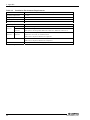
Use the following procedures if you encounter problems using the unit.
(1) Check the front panel LEDs.
The RUN and STATUS LEDs are located on the front panel.
-
Check that the RUN LED is blinking.
-
Check that the STATUS LED is off.
Check that the correct power supply is being provided to the unit.
Power to the Controller Module” in “Chapter 3 Hardware Setup”.
Refer to “Supplying the
(2) Check the network port LED.
Check the UTP connector LED on the front panel.
The LINK LED illuminates when the network cable is correctly connected to the hub. If not
illuminated, refer to “Chapter 2 Module Nomenclature and Settings” and check the connection.
The ACT LED blinks when communication via the network port is in progress.
(3) Use the PING command on a host computer to check if the unit responds.
Ping the IP address assigned to this unit.
If the unit is operating, it should respond.
Example: When the device IP address is 10.1.1.1, the following should be displayed:
ping 10.1.1.1<Enter>:
Reply from 10.1.1.1: bytes=32 time<10ms TTL=255
Reply from 10.1.1.1: bytes=32 time<10ms TTL=255
Reply from 10.1.1.1: bytes=32 time<10ms TTL=255
If you do not know the unit’s IP address, you can restore the factory default setting by holding up
the “SW2” switch when turning on the power.
The RUN LED and STATUS LED start blinking together. The LEDs stop blinking when
initialization completes. Turn off the power and then set the SW2 back to the lower position.
CAUTION
This also resets the other settings.
SVR-MMF2(FIT)
27
5. Setup Troubleshooting
(4) If the unit does not accept the user name and password when connecting from a browser on a host
computer, remember that the user name and password are case sensitive. Check that the Caps
Lock is off then enter again.
You can restore the default factory settings by setting SW2 to the up position and turning on the
power, for example if you have forgotten the user name or password set for the device.
The RUN LED and STATUS LED start blinking together. The LEDs stop blinking when
initialization completes. Turn off the power and then set the SW2 back to the lower position.
CAUTION
This also resets the other settings.
(5) Refer to the "System Setup Guide" for details of the settings.
28
SVR-MMF2(FIT)
6. Appendix
6. Appendix
System Reference
Product Specifications
Table 6.1.
Function Specifications
Item
Specification
Loading CPU
SH-4 240MHz
Memory
Flash ROM : 8Mbyte(64Mbit)
SDRAM : 64Mbyte(512Mbit)
LAN I/F
Controller
F&eIT I/F
Ethernet 100BASE-TX/10BASE-T RJ-45 connector
10/100BASE-TX controller DP83815 made by the National Semiconductor
Transmitting : 2Kbyte, Receiving : in-2Kbyte Buffer
Supported Full-Duplex
Connecting the F&eIT Series Module
Number of connecting devices 8 units (Max.)
*1
Module connecting method
Connect device modules directly to the side of the SVR-MMF2(FIT) .
The connection mechanism is a standard feature on the SVR-MMF2(FIT)
RTC
Lithium battery back-up life expectancy :
When no power supplied : 10 years or more, When power supplied : about 6 years(25°C)
Accuracy of realtime clock : Error of less than one minute per month
Rated input voltage
Supply 5VDC +/-5% to the two-piece power supply input (detachable) connector on the
front of the unit.
Use of a F&eIT series power supply unit is recommended. Alternatively use a standard
stabilized power supply.
Current consumption
0.5A(Max.) *2
(This does not include any current supplied to device units.)
FG pin
An FG terminal is provided on the power supply input connector
External dimension(mm)
25.2(W) x 64.7(D) x 94.0(H) (No protrusion.)
Weight
100g
Installing method
One-touch connection to 35mm DIN rails
(standard connection mechanism provided in the system)
*1 : Ensure that the sum of the maximum current consumptions for each unit does not exceed the rated current output
of the power supply unit.
*2 : The power supply to the device modules is supplied via the stack connector.
However, note that the maximum
current capacity of the stack connector is 3.0A (Max.).
SVR-MMF2(FIT)
29
6. Appendix
Table 6.2.
Installation Environment Requirements
Item
Operating temperature
Requirement description
0 - 50°C
Storage temperature
-10 - 60°C
Operating humidity
10 - 90%RH (No condensation)
Floating dust particles
Not to be excessive
Corrosive gases
None
Line-Noise
resistance
AC line/2kV, Signal line/1kV (IEC1000-4-4Level 3, EN61000-4-4Level 3)
Vibration
resistance
Line-noise *3
Static electricity Contact discharge/4kV (IEC1000-4-2Level 2, EN61000-4-2Level 2)
resistance
Atmospheric discharge/8kV (IEC1000-4-2Level 3, EN61000-4-2Level 3)
Sweep
resistance
10 - 57Hz/semi-amplitude 0.15mm, 57 - 150Hz/2.0G
40minutes each in X, Y, and Z directions
(JIS C0040-compliant, IEC68-2-6-compliant)
Impact resistance
15G half-sine shock for 11ms in X, Y, and Z directions
(JIS C0041-compliant, IEC68-2-27-compliant)
Ground
D-type ground(old the third-type ground)
*3 When using a POW-AD22GY
30
SVR-MMF2(FIT)
6. Appendix
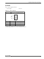
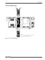
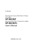
External dimensions
14.0
(1.2)
45.0
94.0
35.0
14.0
*31.5
(1.2)
ACT
LINK
3.5
25.2
64.7
5.0
SVR-MMF2
4.0
[mm]
* shows the center position of the DIN rail.
( ) shows the referring dimension.
Figure 6.1. External dimensions
SVR-MMF2(FIT)
31
SVR-MMF2(FIT)
Hardware Setup Guide
CONTEC CO.,LTD.
December 2005 Edition
3-9-31, Himesato, Nishiyodogawa-ku, Osaka 555-0025, Japan
Japanese http://www.contec.co.jp/
English http://www.contec.com/
Chinese http://www.contec.com.cn/
No part of this document may be copied or reproduced in any form by any means without prior written
consent of CONTEC CO., LTD.
[12162005]
[04182005]
[12162005_rev2]
Management No. A-46-853
Parts No.
LYDM841