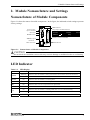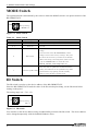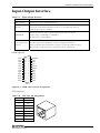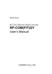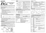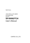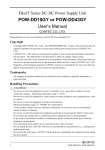
1
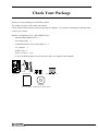
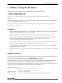
F&eIT Series
GPIB-Ethernet Media Converter
RP-GPIB(FIT)GY
User’s Manual
CONTEC CO.,LTD.
Check Your Package
Thank you for purchasing the CONTEC product.
The product consists of the items listed below.
Check, with the following list, that your package is complete. If you discover damaged or missing items,
contact your retailer.
Product Configuration List < RP-GPIB(FIT)GY >
- Module [RP-GPIB(FIT)GY] ...1
- First Step Guide … 1
- CD-ROM [F&eIT Series Setup Disk] *1…1
- AC Adapter ...1
- Rubber feet ...4
- Piece of Velcro ...2 set
*1 The CD-ROM contains various software and User’s Manual (this manual)
POWER
LISTEN
TALK
SRQ
ERROR
Vi+
5VDCViFG
ID
MODE
GPIB
ERROR
OUT
10M
ACT
LINK
RP-GPIB(FIT)GY
Module
AC adapter
Rubber feet x 4
Piece of Velcro x 2
CD-ROM
First step guide [F&eIT Series Setup Disk]
RP-GPIB(FIT)GY
i
Copyright
Copyright 2003 CONTEC CO., LTD. ALL RIGHTS RESERVED.
No part of this document may be copied or reproduced in any form by any means without prior written
consent of CONTEC CO., LTD.
CONTEC CO., LTD. makes no commitment to update or keep current the information contained in this
document.
The information in this document is subject to change without notice.
All relevant issues have been considered in the preparation of this document. Should you notice an
omission or any questionable item in this document, please feel free to notify
CONTEC CO., LTD.
Regardless of the foregoing statement, CONTEC assumes no responsibility for any errors that may
appear in this document nor for results obtained by the user as a result of using this product.
Trademarks
F&eIT is a registered trademark or trademark of CONTEC CO., LTD. Other company and product
names that are referred to in this manual are generally trademarks or registered trade trademark.
ii
RP-GPIB(FIT)GY
Table of Contents
Check Your Package............................................................................................................................ i
Copyright ............................................................................................................................................ ii
Trademarks ......................................................................................................................................... ii
Table of Contents............................................................................................................................... iii
1.
BEFORE USING THE PRODUCT
1
About the Board.................................................................................................................................. 1
Features ........................................................................................................................................ 1
Support Software ......................................................................................................................... 1
Customer Support ............................................................................................................................... 2
Web Site....................................................................................................................................... 2
Limited One-Year Warranty............................................................................................................... 2
How to Obtain Service ....................................................................................................................... 2
Liability............................................................................................................................................... 2
Safety Precautions .............................................................................................................................. 3
Safety Information ....................................................................................................................... 3
Precautions Related to Service .................................................................................................... 3
Handling Precautions................................................................................................................... 3
Environment................................................................................................................................. 5
Inspection..................................................................................................................................... 5
Storage ......................................................................................................................................... 5
Disposal ....................................................................................................................................... 5
2.
MODULE NOMENCLATURE AND SETTINGS
7
Nomenclature of Module Components............................................................................................... 7
LED Indicator ..................................................................................................................................... 7
MODE Switch..................................................................................................................................... 8
ID Switch ............................................................................................................................................ 8
Input-Output Interface ........................................................................................................................ 9
3.
OPERATION OUTLINE
11
Remote control mode........................................................................................................................ 11
4.
INSTALLATION AND CONNECTION
13
Installation Method........................................................................................................................... 13
Mounting on a DIN Rail ............................................................................................................ 13
Table Top Installation................................................................................................................ 15
Another form of installation ...................................................................................................... 15
Connection ........................................................................................................................................ 16
Cable Connection....................................................................................................................... 16
Connection of a Power Supply .................................................................................................. 18
RP-GPIB(FIT)GY
iii
5.
SETUP
19
Setup Procedures............................................................................................................................... 19
Utility Software................................................................................................................................. 20
Starting of Utility Software ....................................................................................................... 20
Node Registration ...................................................................................................................... 22
Configuration ............................................................................................................................. 23
File Management ....................................................................................................................... 25
Status.......................................................................................................................................... 26
Installing the Driver for Windows.................................................................................................... 28
Correspondence OS ................................................................................................................... 28
Installation ................................................................................................................................. 28
Accessing the Help File ............................................................................................................. 28
Using Sample Programs............................................................................................................. 29
6.
TROUBLESHOOTING
31
When Communication Fails ...................................................................................................... 31
When the RP-GPIB(FIT)GY Will Not Start ............................................................................. 31
7.
SYSTEM REFERENCE
33
Product Specifications ...................................................................................................................... 33
External Dimensions......................................................................................................................... 35
iv
RP-GPIB(FIT)GY
1. Before Using the Product
1. Before Using the Product
This chapter provides information you should know before using the product.
About the Board
This product is a media converter for converting between GPIB interface and Ethernet
interfaces.
This product allows your Windows PC to remotely control a GPIB device conforming to the IEEE-488.1
or IEEE-488.2(GPIB) standard over a LAN.
Please read this manual carefully before performing system configuration such as setting switches or
connecting to external devices.
Features
-
Capable of connecting an IEEE-488.1 or IEEE-488.2 compliant device to a wired LAN (Ethernet)
within the maximum distance restricted by Ethernet.
-
Supplied windows driver allowing a PC to control the connected GPIB device over the LAN.
-
Utility software bundled to easily detect the device, load settings, update firmware, and display
status information. (Supporting Windows Vista, XP, 2000, Me, 98SE, and 98 etc.)
For details, read Help supplied on the CD-ROM.
-
Rotary switch available to set an ID that determines and visibly indicate the device address (0 - 15).
The device address can also be set with software within the range of 0 - 30.
-
A series of LEDs including LISTEN, TALK, and SRQ allowing you to check the current GPIB
communication status at a glance.
-
Like other F&eIT series products, a 35mm DIN rail attachment is fitted to the module as a standard
feature.
Support Software
You should use CONTEC support software according to your purpose and development environment.
Win32 version of RP-GPIB(FIT) driver : API-RPGPIB(W32) (Bundled)
API-RPGPIB(W32) is the library software that provides the commands for RP-GPIB(FIT)GY in the
form of Windows standard Win32 API functions (DLL). It makes it easy to create high-speed
application software taking advantage of the CONTEC hardware using various programming languages
that support Win32 API functions, such as Visual Basic and Visual C/C++.
< Operating environment >
OS
Windows Vista, XP, 2000, Me, 98SE, 98etc..
For details, read Help supplied on the CD-ROM.
Adaptation language
Visual C++, Visual Basic, etc..
Others
Each piece of library software requires 20 megabytes of free hard disk space.
RP-GPIB (FIT)GY
1
1. Before Using the Product
Customer Support
CONTEC provides the following support services for you to use CONTEC products more efficiently and
comfortably.
Web Site
Japanese
English
Chinese
http://www.contec.co.jp/
http://www.contec.com/
http://www.contec.com.cn/
Latest product information
CONTEC provides up-to-date information on products.
CONTEC also provides product manuals and various technical documents in the PDF.
Free download
You can download updated driver software and differential files as well as sample programs available in
several languages.
Note! For product information
Contact your retailer if you have any technical question about a CONTEC product or need its price,
delivery time, or estimate information.
Limited One-Year Warranty
CONTEC products are warranted by CONTEC CO., LTD. to be free from defects in material and
workmanship for up to one year from the date of purchase by the original purchaser.
Repair will be free of charge only when this device is returned freight prepaid with a copy of the original
invoice and a Return Merchandise Authorization to the distributor or the CONTEC group office, from
which it was purchased.
This warranty is not applicable for scratches or normal wear, but only for the electronic circuitry and
original boards. The warranty is not applicable if the device has been tampered with or damaged through
abuse, mistreatment, neglect, or unreasonable use, or if the original invoice is not included, in which case
repairs will be considered beyond the warranty policy.
How to Obtain Service
For replacement or repair, return the device freight prepaid, with a copy of the original invoice. Please
obtain a Return Merchandise Authorization Number (RMA) from the CONTEC group office where you
purchased before returning any product.
*
No product will be accepted by CONTEC group without the RMA number.
Liability
The obligation of the warrantor is solely to repair or replace the product. In no event will the warrantor
be liable for any incidental or consequential damages due to such defect or consequences that arise from
inexperienced usage, misuse, or malfunction of this device.
2
RP-GPIB(FIT)GY
1. Before Using the Product
Safety Precautions
Understand the following definitions and precautions to use the product safely.
Safety Information
This document provides safety information using the following symbols to prevent accidents resulting in
injury or death and the destruction of equipment and resources. Understand the meanings of these labels
to operate the equipment safely.
DANGER
DANGER indicates an imminently hazardous situation which, if not avoided, will
result in death or serious injury.
WARNING
WARNING indicates a potentially hazardous situation which, if not avoided, could
result in death or serious injury.
CAUTION
CAUTION indicates a potentially hazardous situation which, if not avoided, may
result in minor or moderate injury or in property damage.
Precautions Related to Service
Clean the RP-GPIB(FIT)GY by wiping lightly with a soft cloth moistened with water or a cleaning
solution.
Take care to avoid the use of benzene, thinners or other volatile solutions which may cause deformation
or discoloration.
Handling Precautions
CAUTION
-
Do not modify the module. CONTEC will bear no responsibility for any problems, etc., resulting
from modifying this module.
-
Do not use or store the equipment in a hot or cold place, or in a place that is subject to severe
temperature changes.
-
Do not use or store the equipment in a place subject to direct sunlight or near a heating device, such
as a stove.
-
Do not use or store the equipment in a dusty or humid place.
-
Do not use or store the product near equipment generating a strong magnetic field or radio waves.
-
As this product contains precision electronic components, do not use or store in environments
subject to shock or vibration.
-
If you notice any strange odor or overheating, please unplug the power cord immediately.
-
In the event of an abnormal condition or malfunction, please consult the dealer from whom the
equipment was purchased.
-
To avoid electric shock, please do not touch the system with a wet hand.
-
Do not open the module casing. CONTEC will disclaim any responsibility for equipment whose
casing has been opened.
-
To prevent damage, please do not subject the unit to impact or bend it.
RP-GPIB (FIT)GY
3
1. Before Using the Product
-
To prevent contact malfunction, please do not touch the metallic pins on the external module
connector.
-
The module contains switches that need to be properly set. Before using the module, please check
its switch settings.
-
To avoid malfunction, please do not change the module switch settings in an unauthorized manner.
-
Do not modify the RP-GPIB(FIT)GY. CONTEC will bear no responsibility for any problems, etc.,
resulting from modifying this product.
-
Regardless of the foregoing statements, CONTEC is not liable for any damages whatsoever
(including damages for loss of business profits) arising out of the use or inability to use this
CONTEC product or the information contained herein.
FCC PART 15 Class A Notice
NOTE
This equipment has been tested and found to comply with the limits for a Class A digital
device, pursuant to part 15 of the FCC Rules. These limits are designed to provide reasonable
protection against harmful interference when the equipment is operated in commercial
environment.
This equipment generates, uses, and can radiate radio frequency energy and, if not installed
and used in accordance with the instruction manual, may cause harmful interference to radio
communications. Operation of this equipment in a residential area is likely to cause harmful
interference at his own expense.
WARNING TO USER
Change or modifications not expressly approved the manufacturer can void the user's
authority to operate this equipment.
4
RP-GPIB(FIT)GY
1. Before Using the Product
Environment
Use this product in the following environment. If used in an unauthorized environment, the board may
overheat, malfunction, or cause a failure.
Operating temperature
0 - 50°C
Operating humidity
10 - 90%RH (No condensation)
Corrosive gases
None
Floating dust particles
Not to be excessive
Inspection
Inspect the product periodically as follows to use it safely.
* Check that the ventilation slit has no obstruction and
has no dust or foreign matter adhering.
POWER
LISTEN
ERROR
TALK
SRQ
Vi+
5VDC ViFG
ID
MODE
GPIB
ERROR
OUT
10M
ACT
LINK
RP-GPIB(FIT)GY
* Check that the bus corner of the module
and its cable has been plugged correctly.
Storage
When storing this product, keep it in its original packing form.
(1) Put this product in the storage bag.
(2) Wrap it in the packing material, then put it in the box.
(3) Store the package at room temperature at a place free from direct sunlight, moisture, shock,
vibration, magnetism, and static electricity.
Disposal
When disposing of the product, follow the disposal procedures stipulated under the relevant laws and
municipal ordinances.
RP-GPIB (FIT)GY
5
1. Before Using the Product
6
RP-GPIB(FIT)GY
2. Module Nomenclature and Settings
2. Module Nomenclature and Settings
Nomenclature of Module Components
Figure 2.1 shows the names of module components. In the figure, the indicated switch settings represent
factory settings.
POWER
LISTEN
ERROR output
connector
UTP connector
Vi+
5VDC
LED indicator
Large figure of LED indicator
ViFG
ID
MODE
GPIB
POWER
LISTEN
ERROR
SRQ
TALK
Interface connector(GPIB)
ERROR
OUT
ACT
LED Indicator
10M
MODE switch
TALK
SRQ
ERROR
Power supply
input connector
ID switch
LINK
RP-GPIB(FIT)GY
Figure 2.1. Nomenclature of Module Components
CAUTION
Do not block the ventilation vents as this may result in damage or malfunction due to overheating.
LED Indicator
Table 2.1.
LED Name
POWER
LED Display
Status
Flashing
Indicator
Indicates that the module is being activated or an activation error has occurred.
On
Indicates that the module is active.
LISTEN
On
Indicates that the module is receiving data.
TALK
On
Indicates that the module is sending data.
SRQ
On
Indicates that a service request has been generated.
ERROR
On
Indicates that a GPIB interface error has occurred.
ACT
LINK
On
Flashing
On
RP-GPIB (FIT)GY
Indicates that the module is sending LAN data or is not communicating.
Indicates that the module is receiving LAN data.
Indicates that the module has been connected to a LAN.
7
2. Module Nomenclature and Settings
MODE Switch
The operation mode is determined by the value to which the MODE switch is set upon activation of the
RP-GPIB(FIT)GY.
MODE
Factory setting :
(MODE = 0)
Figure 2.2. Mode Switch
Table 2.2.
Mode Switch
MODE Switch value
Operating mode
0
Remote control mode
2-5
Reserved
Description
Causes the module to operate in remote control mode.
Not used.
Resets the RP-GPIB(FIT)GY settings to their factory
settings.
Upon activation of the RP-GPIB(FIT)GY, all the
6
Reset mode
settings return to their factory settings. They will
take effect the next time you will start the module.
* Before restarting or shutting down, make sure that
only the POWER LED is on (with all of the
ERROR, LISTEN, TALK, SRQ LEDs off).
Select this mode to update the module’s firmware.
7
Firmware update mode
Usually, the firmware can be updated in any mode.
If the firmware stops getting started normally,
update it in this firmware update mode.
ID Switch
The ID switch is used to set the device address of the RP-GRIB(FIT)GY.
Since the RP-GPIB(FIT)GY loads the value of the ID switch upon startup, set the ID switch before
turning on the power.
The setting range is 0 - F (0 - 15).
ID
Factory setting :
(ID = 0)
Figure 2.3. ID Switch
You can also set the device address using a bundled utility instead of the ID switch. The device address
can be changed temporarily with the bundled Windows driver.
8
RP-GPIB(FIT)GY
2. Module Nomenclature and Settings
Input-Output Interface
Table 2.3.
Input-Output Interface
Name
Function
GPIB connector
Connector to connect the GPIB interface
Port used for networking
UTP Port
Connected in full-duplex/half-duplex mode at an automatically detected
communication speed of 10 Mbps
Output specification : Opto-coupler-insulated open-collector output
Output rating : 30VDC(Max.), 10mA(Min.)
ERROR-OUT
Response time : 100µsec(Max.)
5VDC±5%
Power supply input
Two-piece power input detachable connector equipped with FG pin
connector
Coming standard with horizontally accessible, screw-locked dedicated plug
(MC1.5/3-ST-3.5 Phoenix Contact Compatible cables : AWG28-16)
GPIB connector
GND
GND
GND
GND
GND
GND
GND
REN
DIO8
DIO7
DIO6
DIO5
24
23
22
21
20
12
11
10
9
8
19
18
17
16
15
14
13
7
6
5
4
3
2
1
SHIELD
ATN
SRQ
IFC
NDAC
NRFD
DAV
EOI
DIO4
DIO3
DIO2
DIO1
CN1
Figure 2.4. GPIB connector Pin Assignments
UTP connector
Table 2.4.
UTP Port Pin Assignments
Pin No.
Signal
1
TD+
2
TD-
3
RD+
4
Not used
5
Not used
6
RD-
7
Not used
8
Not used
RP-GPIB (FIT)GY
9
2. Module Nomenclature and Settings
Error-Output connector
Table 2.5.
Error-Output
Function
Output specification
Response to error detection
The detection circuit remains
Output specification :
made.
Opto-coupler-insulated open-collector to off upon detection of a GPIB
The output is switched from on
Upon detection of an error, the
output
circuit is broken, turning the
Output rating :
output on from off.
30VDC(Max.), 10mA(Min.)
(The output is normally on.)
Response time : 100µsec(Max.)
interface error.
Reference equivalent circuit
Error output pin
Loading
Error detection
circuit
COM
- External power supply +
30VDC(Max.)
Figure 2.5. Reference equivalent circuit
Error-Output connector
- Connector used
COM
S 2B-EH [Made by JST]
Output
- Applicable plug
Housing EHR-2 [Made by JST]
Contact SHE-001T-P0.6 [Made by JST]
Applicable cable AWG#30 - #22
Figure 2.6. Error-Output connector
10
RP-GPIB(FIT)GY
3. Operation Outline
3. Operation Outline
Remote control mode
With the remote control driver for Windows installed on your PC, you can operate the remote GPIB
interfaced device connected to the RP-GPIB(FIT)GY over a LAN as if the device were placed by your
side
When using an application on the PC to operate the GPIB device, specify the IP address of the RPGPIB(FIT)GY to be remote-controlled.
PC
Wired LAN(Ethernet)
RP -G PIB(FIT)GY
RP-GPIB(FIT)GY
GPIB device
Figure 3.1. Remote control mode
CAUTION
To avoid any adverse effects on other LAN devices, set the IP address, subnet mask, and other
network parameters to appropriate values.
RP-GPIB (FIT)GY
11
3. Operation Outline
12
RP-GPIB(FIT)GY
4. Installation and Connection
4. Installation and Connection
Installation Method
Mounting on a DIN Rail
Mounting procedure
(1) Pushing the fixing hook with a flat-blade screwdriver renders it into a lock-enabled condition (this operation
should be done on all connected modules).
35mmDIN rail
Please here to lift the fixing hook.
Figure 4.1. Mounting on a DIN Rail < 1 / 3 >
(2) Hook the unit (an object consisting of a controller and a module) from the upper part of the DIN rail,
and press the lower part of the unit onto the DIN rail.
Side view
Figure 4.1. Mounting on a DIN Rail < 2 / 3 >
(3) The fixing hook is automatically locked, and the module can be mounted in one-touch.
Fixing hook
Side view
Figure 4.1. Mounting on a DIN Rail < 3 / 3 >
RP-GPIB (FIT)GY
13
4. Installation and Connection
Removal procedure
(1) Lower the fixing hook for the unit to unlock it (this operation should be performed on all connected
modules).
35mmDIN rail
Figure 4.2. Removing the Module from the DIN Rail <1 / 3 >
(2) With the fixing hook unlocked, pull the lower part of the unit toward you.
Side view
Figure 4.2. Removing the Module from the DIN Rail < 2 / 3 >
(3) By lifting the unit, you can easily remove it from the DIN rail.
Side view
Figure 4.2. Removing the Module from the DIN Rail < 3 / 3 >
14
RP-GPIB(FIT)GY
4. Installation and Connection
Table Top Installation
Use the rubber pads included with the unit.
To install on a table top, choose a sturdy, level surface with a well-ventilated space (approx. 5cm.) in all
directions.
CAUTION
Do not obstruct the ventilation slits. This can cause the temperature inside the product to rise and
can damage the components inside.
Another form of installation
You can attach it to the instrument by using the piece of Velcro with this product.
To install on a table top, choose a sturdy, level surface with a well-ventilated space (approx. 5cm.) in all
directions.
CAUTION
-
Do not obstruct the ventilation slits. This can cause the temperature inside the product to rise
and can damage the components inside.
The seal is strongly adhesive but its adhesion may not be enough depending on the material of
the target. The Velcro tape can be removed when an excessive force is applied, for example, to
the cable. In such cases, the RP-GPIB(FIT)GY may fall, possibly resulting mechanical
damages or malfunctions. Use meticulous care not to let the module fall.
RP-GPIB (FIT)GY
15
4. Installation and Connection
Connection
Cable Connection
GPIB Cable Connection
The GPIB has restrictions on the number of devices connected and the cable length according to the
standard.
(1) The maximum number of interfaces (external devices) is 15, which can be connected to one system.
(2) The maximum total length of cables that can be used to interconnect a group of devices in one bus
system is “2 m x (the number of devices)” or 20 m, whichever is shorter. (JIS C1901-1987).
Some examples are given below.
-
System with a total of two devices
2 m x (Number of devices = 2) < 20 m. The maximum total length of cables for this
system is therefore 4 m.
POWER
LISTEN
ERROR
TALK
SRQ
Vi+
5VDCViFG
ID
MODE
GPIB
3765
ERROR
OUT
10M
ACT
LINK
RP-GPIB(FIT)GY
-
-
System with a total of three devices
The maximum total length of cables for this system is therefore 6 m. The two cables used
in the system must be [2 m + 4 m] or [2 m + 2 m] in length so that neither is longer than
4m.
System with a total of fifteen devices
2 m x (Number of devices = 15) > 20 m. The maximum total length of cables for this
system is therefore 20 m.
POWER
LISTEN
ERROR
TALK
SRQ
Vi+
5VDCViFG
ID
MOD E
GPIB
3765
ERROR
O UT
10M
ACT
3765
•••
3765
LINK
(3) Unplug the cable from any device which is left off for some reason such as a fault.
POWER
LIST EN
TALK
SRQ
ERROR
Vi+
5VDCViFG
ID
MODE
GPIB
ERROR
OUT
3765
3765
10M
ACT
LINK
16
RP-GPIB(FIT)GY
4. Installation and Connection
(4) Unplug the cable from any device which is left off for some reason such as a fault.
(5) When powering the measurement system, turn on the measuring instrument first and then on the PC.
(6) Neither unplug/plug the cable nor turn on/off the device during communication. Doing so stops the
operation or causes an error, resulting in trouble.
(7) The talker and listener must be addressed to talk and to listen, respectively, by the controller before
the talker can send messages to the listener.
(8) After completing all the required cable connections, turn on the power to the RP-GPIB(FIT)GY.
(9) Treat the GPIB cable carefully not to apply an excessive force to the GPIB connector of
the RP-GPIB(FIT)GY.
UTP Cable Connection
Connect the UTP connector to the UTP cable.
<Cable Specifications>
Cables complying with the following specifications should be used:
Category 3, 4, 5 UTP cable
RP-GPIB (FIT)GY
17
4. Installation and Connection
Connection of a Power Supply
Connect the supplied AC adapter to the power input connector.
You can also connect a power supply unit (sold separately) (POW-AD13GY, POW-AD22GY, POWAD25GY, POW-DD10GY, POW-DD42GY). To connect a power supply unit to the RP-GPIB(FIT)GY,
connect the cable to the removable connector on the unit or module face.
(Applicable cables: AWG 28 - 16)
CAUTION
Because the power supply unit generates heat, a minimum spacing of 2.cm should be provided
between the RP-GPIB(FIT)GY and any adjoining units, and care should be taken so that the
ventilation holes are not covered.
<An appending AC adapter is used>
POWER
LISTEN
AC adapter
TALK
SRQ
ERROR
Vi+
5VDC Vi-
FG
ID
MODE
GPIB
ERROR
OUT
10M
ACT
LINK
RP-GPIB(FIT)GY
<An optional power supply unit is used>
Cable connection
CONTEC
POWER
POWER
LISTEN
ERROR
TALK
SRQ
Vi+
Vo+
5VDC Vi-
5VDC Vo-
FG
FG
ID
MODE
GPIB
10 to 30VDC
ERROR
OUT
Vo+
FG
ACT
10M
Vo-
LINK
POW-DD10
RP-GPIB(FIT)GY
(Ex : POW-DD10GY)
Figure 4.3. Connection of a Power Supply
18
RP-GPIB(FIT)GY
5. Setup
5. Setup
Setup Procedures
When installing the RP-GPIB(FIT)GY in a network, set the module’s unique IP address different from
any of the IP addresses of the other networked devices.
Use the bundled utility software to set the IP address.
Setting up the module
(1) Set the MODE switch.
Set the MODE switch on the front panel to the desired mode. For details, see “MODE Switch” in
Chapter 2 “Module Nomenclature and Settings”.
(2) Set the ID switch.
Use the ID switch on the front panel to set the device address.
For the device address, you can use the utility to select whether to use the ID switch value (0 to 15)
on the front panel or the address (0 to 31) set with the utility.
(3) Connect the power cable and network cable to the RP-GPIB(FIT)GY.
Installing the utility software
(1) Check the utility software installation environment.
OS
Windows Vista, XP, 2000, Me, 98SE, 98 etc.
Main body : The PC to install the utility software on must have any of the above operating
systems running and can be networked via TCP/IP.
For details, read Help supplied on the CD-ROM.
(2) Prepare the PC before installation.
Close any programs you have running on the PC to install the utility software on. If any screen
saver or virus detection software is running, stop them temporarily.
(3) Start installation.
Load the bundled CD-ROM on the CD drive.
Menu will be shown. Select [API-RPGPIB(W32)] and install it.
(4) Follow the installation instructions on the screen to continue with the installation.
When the utility software has been installed normally, the program is registered.
(5) Start the application and check notes on it.
Set the IP address of RP-GPIB(FIT)GY
(1) From the Start menu, choose “Programs” -> “API-RPGPIB(W32)” and start “Utility”.
(2) Select “Configuration” from the Utility menu.
(3) Select the “Base” tab and set the IP address and subnet mask.
See “Utility Software” in this chapter for details on how to use the utility software.
When you have finished setting up the module, restart your PC to make the settings take effect.
RP-GPIB (FIT)GY
19
5. Setup
Utility Software
This is a Windows application for detecting devices on the network, reading and writing setup data,
upgrading firmware, and displaying status information.
These maintenance operations can be performed from a Windows PC via the LAN port.
Starting of Utility Software
Upon activation of the “Utility” From the Start menu, choose “Programs” -> “API-RPGPIB(W32)”,
“Utility software” is started.
You will see the following main menu.
Figure 5.1. Main menu
20
RP-GPIB(FIT)GY
5. Setup
Node Registration
Edits the access point name list.
This list is used to detect devices connected by wired or wireless connection. Device names are added or
deleted using the edit function.
Configuration
Maintains configuration information.
View or enter settings for the selected devices.
File Management
Used for firmware maintenance.
View firmware version, or write firmware.
Status
Displays access point information.
View and verify information about the selected device.
Exit
Program exit.
RP-GPIB (FIT)GY
21
5. Setup
Node Registration
This registers data for the devices on the network. Maintenance operations such as changing settings or
upgrading the firmware are performed based on the data registered here. You must always perform node
registration
Assigning names to the devices found by the automatic search makes it easier to identify the devices on
the network.
Enter a name of up to 32 characters. A maximum of 1024 devices can be registered.
Figure 5.2. Node Registration
Button
Description
This automatically detects and registers all devices connected to the same
Search
network group. If you also wish to manage devices located on the far side of an
IP router, use the “New” button to register each device directly.
Clear
Deletes all registered data.
New
Registers data for a new device to be managed.
Delete
Deletes the data for the device selected in the node list
Exit
Returns to the main menu.
To modify the data displayed in the node list, double click on the node you wish to modify to open an edit
window.
You can also use the “File” menu to save the current node list data to the hard disk or load a previously
saved file.
22
RP-GPIB(FIT)GY
5. Setup
Configuration
This reads and writes the settings for the device selected in the “Node Name” field.
You can set basic parameters such as the operation mode as well as advanced parameters.
To apply your changes, write the settings to the device and then reboot it.
You can also use the “File” menu to save the currently displayed settings to the hard disk or load a
previously saved file.
Button
Description
Change the password for the selected device.
Password
To change, enter the current password and new password.
The new password does not become active until the device is rebooted.
The password can be up to 6 alphanumeric characters and is case sensitive.
Read
Write
Default
Read the settings for the selected device.
Write the currently displayed settings to the selected device.
The new settings do not become active until the device is rebooted.
Restore the factory default settings.
To apply these settings, write the settings to the device and then reboot it.
Reboot
Reboot the selected device.
Exit
Returns to the main menu.
* Password input is required for the “Password”, “Read”, “Write”, and “Reboot” commands.
The factory default setting is no password. In this case, you do not need to enter anything.
RP-GPIB (FIT)GY
23
5. Setup
Base Configuration
This sets the IP parameters and other basic operating settings for the device. You must always set the IP
parameters if installing the device in an existing network.
Figure 5.3. Base Configuration
Parameter
Factory setting
IP Address
10.x.x.x*1
Subnet Mask
255.0.0.0
Default Gateway
0.0.0.0
Mode
Master
My address
0
Delimiter
CF+LF / Enable EOI
Input range
Description
Set the IP address mask assigned by the
network administrator.
Set the subnet mask assigned by the
network administrator.
Set the IP address of the default gateway.
Fixed at Master
0 to 30 assigned
with ID switch.
Specify the operating mode.
Set my address.
Not used / CR/LF / CR+LF
Set the delimiter for transmission and
Enable or disable EOI.
reception and enable or disable EOI.
*1 : Factory setting of IP Address
A unique value is assigned using the lower 3 bytes of the 6-byte Ethernet address.
(Example)
Ethernet address
IP address
00-80-4C-01-02-03
→
10.1.2.3
00-80-4C-0D-0E-0F
→
10.13.14.15
The initial '10' is common to all settings.
24
RP-GPIB(FIT)GY
5. Setup
File Management
This dialog is used to get the current firmware version of devices on the network, perform firmware
upgrades, and read or write the settings file.
Figure 5.4. File Management
Button
Description
Retrieves the version number from all devices connected to the same network group or from a specified
Get Version
device only. To get information from devices on the other side of a router, you need to specify the device
explicitly. In this case, the device’s IP address must have been set correctly.
Read
Read the firmware and settings file and save on the hard disk. *1
Write
Write the firmware and settings file from the hard disk to the selected device. *1
Reboot
Reboot the selected device.
Exit
Returns to the main menu.
Select the file and directory name.
Type
Browse
Selected File
Firmware
File Name
Configuration File
Directory Name
*1: File name
The file name contains the lower 3 bytes of the MAC address of the selected device.
(Example) Ethenet address
00-80-4C-01-02-03 →
RP-GPIB (FIT)GY
IP address
010203.TXT
25
5. Setup
Status
Reads operating information such as the environment settings and the send and receive counters from the
device specified by “Node Name” and displays on the screen. The send and receive counters can also be
cleared. However, data can only be cleared when scanning is stopped.
Button
Exit
Description
Returns to the main menu.
Scan Start
Stop
Reads data periodically (at the number of seconds specified by “Interval”).
If “Interval” is “0”, data is read once only.
Stops reading data.
Environment
Displays the current operating environment for the specified device.
Figure 5.5. Status (Environment)
Parameters
Loader Version
Description
Version number of program for executing firmware.
Firmware Version
The version number of a firmware.
Hardware Version
The version number of a hardware.
ID
The device address set by ID switch now.
Ethernet Address
Ethernet address assigned to this device.
IP Address
Current IP address set for device.
Subnet Mask
The subnet mask set up now.
Default Gateway
The IP address of the default gateway set up now.
26
RP-GPIB(FIT)GY
5. Setup
Interfaces
Displays data for the device’s GPIB and Ethernet interfaces including send and receive counters.
The counters can be cleared when scanning is stopped.
Figure 5.6. Status (Interfaces)
Parameter
MTU
Speed
MAC Address
Description
Maximum data size able to be sent by this interface. The GPIB side is indeterminate.
Transmission speed for sending data from this interface.
The GPIB side is indeterminate.
MAC address assigned to this interface. No MAC address is set for the RS-232C interface.
The GPIB side is indeterminate.
The state of an interface of operation.
Interface
Receive Octets
up
: An interface is operating.
down
: Not operating or no link.
The number of bytes of the received data.
Receive Packets
The received number of packets
Receive Discards
The number which canceled the receiving packet by the shortage of a memory etc.
Receive Errors
The number of packets which the reception error generated.
Transmit Octets
The number of bytes of the transmitted data.
Transmit Packets
The transmitted number of Packets.
Transmit Waits
The number of the packet which is carrying out waiting for transmission.
Transmit Errors
The number of packets which the transmitting error generated.
Resets
The number of times which reset this interface.
RP-GPIB (FIT)GY
27
5. Setup
Installing the Driver for Windows
Correspondence OS
The “Win32 version of RP-GRIP(FIT) driver” for Windows used in the remote control mode supports
Windows Vista, XP, 2000, Me, 98SE and 98 etc.
For details, read Help supplied on the CD-ROM.
For details on API-RPGPIB(W32), refer to the help file.
Installation
Installation procedure
(1) Load the bundled CD-ROM on the CD drive.
Menu will be shown. Select [API-RPGPIB(W32)] and install it.
(2) Follow the installation instructions on the screen to continue with the installation.
When the utility software has been installed normally, the program is registered.
Uninstallation procedure
(1) Select [Add/Remove Program] from [Control Panel].
(2) Select “API-RPGPIB(W32)” from the ”Currently installed programs:” list, then click the
[Change/Remove] button.
(3) Follow the uninstall instructions on the screen to continue with the uninstallation.
When the driver has been uninstalled normally, the program is deleted.
Accessing the Help File
(1) From the Start menu, choose “Programs” -> “API-RPGPIB(W32)” and start “Help”.
28
RP-GPIB(FIT)GY
5. Setup
Using Sample Programs
Bundled sample programs cover basic polling in master modes and support ADVANTEST Multimeters,
YEW voltage generators, and SONY Tektronix oscilloscopes.
Use these sample programs as references for program development and operation check.
The sample programs are stored in \Program Files\CONTEC\API- RPGPIB(W32)\Samples.
Running a Sample Program
(1) From the Start menu, choose “Programs” -> “API-RPGPIB(W32)” and start “Sample…..”.
(2) A sample program is invoked.
RP-GPIB (FIT)GY
29
5. Setup
Sample Programs – Examples
- Master Mode
:
Executes a series of operations in master mode.
- Multi-meter
:
Triggers a multimeter periodically (based on the timer and
events) to sample and display data.
- Voltage Source control :
fixed
Allows the master to gain control of a digital voltmeter at
intervals.
- Oscilloscope 1
:
Receives screen data from an oscilloscope and displays it in
a graph.
- Oscilloscope 2
:
Receives screen data from an oscilloscope and saves it in
CSV format.
- MultiLine Message
:
Send a multiline message for the remote device.
[Master Mode]
[MultiLine Message]
[Voltage Source control]
[Oscilloscope]
30
RP-GPIB(FIT)GY
6. Troubleshooting
6. Troubleshooting
This chapter describes common problems that may occur with this product and what to do about them. If
any problems occur that are not described here, check to confirm that the re-occur, then contact the store
where you purchased the product, or the CONTEC information center.
When Communication Fails
Check hardware
-
Check that the LAN cables are connected correctly.
-
Check that the GPIB cables are connected correctly.
-
Is the MODE switch set correctly?
-
Is the ID switch set correctly?
-
Is the operating mode set correctly?
Check software
-
Are the IP address and subnet mask set correctly?
-
Is the device address set by correctly selecting the hardware setting (ID switch) and software setting
(utility software)?
-
Are the delimiter set correctly?
When the RP-GPIB(FIT)GY Will Not Start
Check the power LED
-
Be sure the power LED is on. If not, check that the AC adapter, power supply connector, and mains
power plug are connected correctly.
-
If the POWER LED does not illuminate within 3 minutes of turning on the power or
resetting via the utility software, first check whether the MODE switch is set to “0”.
-
If the MODE switch is not set to “0”, change to “0”, then restart.
-
If the MODE switch is set to “0”, it is possible that the firmware is faulty.
In this case, use the utility software to update the firmware.
RP-GPIB (FIT)GY
31
6. Troubleshooting
32
RP-GPIB(FIT)GY
7. System Reference
7. System Reference
Product Specifications
Table 7.1.
Functional Specification
Specification
GPIB unit
GPIB standard
RP-GPIB(FIT)GY
IEEE488.1 or IEEE488.2
Channel No.
1ch
Data transfer
8-bit parallel / 3-lines handshake type
Signal logic
Negative logic
L level … 0.8V or less
H level … 2.0V or more
Wired LAN
Ethernet standard
IEEE802.3
unit
Data transmission speed
10Mbps
Access method
CSMA/CD
Communication system
Half Duplex / Full Duplex
Number of ports
1(10BASE-T)
Supply voltage
5.0VDC ±5% (An AC adapter is provided)
Current consumption
0.6A (Max.)
50.4(W) x 64.7(D) x 94.0(H)
Dimensions (mm)
(Not including protruding parts.)
Weight
190g
Table 7.2. Installation Environment Conditions (Environment Specifications)
Parameter
Operating temperature
Requirement description
0 - 50°C
Storage temperature
-10 - 60°C
Operating humidity
10 - 90%RH (No condensation)
Floating dust particles
Not extreme
Corrosive gases
None
Line-Noise resistance
Line-noise *
AC line/2kV, Signal line/1kV (IEC1000-4-4Level 3, EN61000-4-4Level 3)
Static
Contact discharge/4kV (IEC1000-4-2Level 2, EN61000-4-2Level 2)
electricity
resistance
Vibration resistance
Impact resistance
Grounding
Sweep
resistance
Atmospheric discharge/8kV (IEC1000-4-2Level 3, EN61000-4-2Level 3)
10 - 57Hz/semi-amplitude 0.15mm, 57 - 150Hz/2.0G
80minutes each in X, Y, and Z directions
(JIS C0040-compliant, IEC68-2-6-compliant)
15G, half-sine shock for 11ms in X, Y, and Z directions
(JIS C004-compliant, IEC68-2-27-compliant)
Class D grounding (previous class 3 grounding)
* : At the time of appending AC adapter use
RP-GPIB (FIT)GY
33
7. System Reference
Table 7.3.
Software Specifications
Specification
RP-GPIB(FIT)GY
IP (RFC 791), ICMP (RFC 792), UDP (RFC 768),
Protcols
ARP (RFC 826)
Table 7.4.
AC Adapter Environmental Conditions (Environmental Specs)
Specification
RP-GPIB(FIT)GY(Accessory)
AC supply voltage
100 - 240VAC 0.3.A(Max.)
AC supply frequency
50 - 60Hz
DC supply voltage
5VDC ± 5% 2.0A(Max.)
Operating temperature
0 - 40°C
Operating humility
10 - 90%RΗ (No condensation)
Airborne dust
Not extreme
Corrosive gases
None
Table 7.5.
Interface function
Code
SH1
Function
Source handshake functions
AH1
Acceptor handshake functions
T6
Basic talker, serial polling, MLA talker release
L4
Basic listener MTA listener release
TE0
No extended talker functions
LE0
No extended listener functions
PP1
Configuration by remote message
C1
System controller function
C2
IFC send, controller in-charge
C3
REN send
C4
Response to SRQ
C26
Interface message send, parallel polling
34
RP-GPIB(FIT)GY
7. System Reference
External Dimensions
(1.2)
POWER
LISTEN
14.0
14.0
31.5
(1.2)
(1.2)
TALK
SRQ
ERROR
Vi+
5VDC Vl-
35.0
FG
MODE
GPIB
94
ID
45.0
ERROR
OUT
10M
ACT
LINK
3.5
50.4
(1.2)
RP-GPIB(FIT)GY
(7)
64.7
4
[mm]
Figure 7.1. External Dimensions
RP-GPIB (FIT)GY
35
RP-GPIB(FIT)GY
User’s Manual
CONTEC CO., LTD.
April 2007 Edition
3-9-31, Himesato, Nishiyodogawa-ku, Osaka 555-0025, Japan
Japanese http://www.contec.co.jp/
English http://www.contec.com/
Chinese http://www.contec.com.cn/
No part of this document may be copied or reproduced in any form by any means without prior written
consent of CONTEC CO., LTD.
[04122007]
[10082003]
[04122007_rev4]
Management No. A-46-805
PartsNo.
LYDB672