1
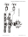
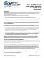
Using the CRS-100 with CDM-550/600 Modems in Switched Diversity Applications Application Note Introduction Switched diversity systems are those employing two or more antennas for the purpose of maintaining a communications link should the signal from one of those antennas become blocked, or severely degraded. A system is employed that switches between antennas, or more commonly, the entire signal processing chain. In satellite communications, a switched diversity system is usually employed in situations where: 1. The ground station is mobile (such as a ship) and direct line-of-sight is blocked by tall buildings, bridges, fjords, etc. Or: 2. The ground station is fixed, but where there is frequent blockage of an antenna (such as an oil drilling platform, where helicopter traffic interrupts the line-of-sight view to the satellite). In these circumstances, two (or more) antennas are employed that are physically separated (or diverse) by sufficient distance that when one antenna is blocked, there is a very high probability that the other antenna(s) will still maintain a clear view of the satellite. Hence, the system is called Switched Diversity. It is vitally important to successfully detect when the antenna has become blocked, and it is very convenient therefore to simultaneously receive and demodulate the signal coming from each antenna, and to make the decision to switch based on either: 1. A simple comparison of the lock/unlock status of the two demodulators – if an antenna becomes blocked and its associated demod loses signal acquisition, while the other antenna/demod remains in lock, then it can be correctly concluded that the system should switch to the other antenna/demod. If both antenna/demod paths simultaneously report loss of acquisition (both antennas simultaneously blocked, or in a severe rain fade), then no switch should occur. Or: 2. A comparison of the signal quality reported by the two demodulators – in this way, an Eb/No value can be defined that guarantees a certain quality of service (QoS). If one antenna should become partially blocked, and the Eb/No falls below the defined QoS threshold, then the system should switch to the other antenna/demod path. The system should have sufficient intelligence to ensure that, if both antenna/demod paths are below the QoS threshold, no switch should occur. It should be noted that in full duplex links that this system works without modification – antenna blockages that affect the receive link equally affect the return transmit link. The entire transmit/receive system can be switched together to ensure continuity of both link directions. The CRS-100 Redundancy Switch – Background The CRS-100 is a Redundancy Switch whose primary purpose is to provide 1:1 protection of a pair of Comtech Modems (either CDM-550 or CDM-600). The purpose of this application note is to show how the CRS-100 can be used, in a very easy manner, to control a switched diversity system, in both the ‘simple’ mode, and in the QoS mode. The CRS-100 contains switching elements that route IF and data signals from a pair of modems to a set of common interfaces. It also contains an intelligent controller that monitors fault information from the two modems (the On-line and Off-line units), and decides what action to take. A comparison is made between the fault information from the two units – if the same fault is seen at the same time from both modems, it is assumed that some common external factor has caused this condition, and that no switchover is necessary. An example of this would be if both demods simultaneously report a loss of demod lock – this would almost certainly not indicate that both pieces of equipment had failed at the same instant of time – an external condition is to blame, such as a severe rain fade. The modems report ‘hard’ faults (referred to as Unit faults) such as the failure of a power supply, or a synthesizer. In addition, the modems report traffic alarms (Receive Traffic and Transmit Traffic) which reflect the state of traffic signals being fed to the modem, and which are being monitored by the modem’s internal circuits. If the user desires, the Comtech modems can be configured to generate a Receive Traffic alarm when the Eb/No falls below a user-defined threshold. Copyright 2002 Comtech EF Data Corp. –1– AN/CRS100_DIVERSITY.DOC 1/28/02 Using the CRS-100 with CDM-550/600 Modems in Switched Diversity Applications In the CRS-100, the user can then define those conditions that will cause a switchover to occur. A ‘hard’ fault (Unit Fault) always causes a switchover, and selector switches on the side of the unit define whether Receive Traffic alarms, Transmit Traffic Alarms, or both, will also cause a switchover. In 1:1 mode, the two modems are fed with identical Receive IF signals – the CRS-100 contains a power splitter. On the transmit side, however, only one unit can have its transmit output active, and the CRS-100 mutes the output of the Off-line unit, using two methods. First, it uses a hardware control line (present on the interface connector) that directly turns off the Tx carrier. By itself, this provides approximately 80 dB on/off ratio. In addition, there is an RF switch in the CRS-100 that provides even higher overall isolation. The data port (which can be RS422, V.35 or RS232) is buffered and switched so that both modems simultaneously receive the same transmit data, and the On-line modem provides the receive data. The CRS-100 does not require an external power supply – it derives its operating current from the modem(s) to which it is connected. Synchronizing Modem Configurations in a 1:1 Pair Note also that the 1:1 system has an additional important feature. On the rear panel of each modem an ‘Auxiliary Serial Port’ is provided. In a 1:1 system a short cable connects this port to the other modem in the 1:1 pair. A full duplex serial link is established between the two units, and status information is continuously exchanged. Now, if a user changes the configuration of the On-line unit, the other unit is immediately reprogrammed to reflect this new configuration without any intervention from the user. It is critically important in a 1:1 system to ensure that both modems are configured identically, and if this is a manual process, mistakes can occur. This system completely eliminates the risks of a manually configured system. It goes without saying that this applies equally well for modems in a switched diversity system. Using the CRS-100 Redundancy Switch in Switched Diversity Applications So how can the CRS-100 be used to control modems in a switched diversity system? The Figure on the following page illustrates how this can be accomplished. The system comprises two identical signal chains – two antennas, two RF terminals, two modems, under control of the CRS-100. The two antennas are assumed to be physically separated by sufficient distance to meet the system requirements. The CRS-100 provides a common user data port to the user. The system is configured in an almost identical manner to a ‘normal’ 1:1 system, with the exception that the IF ports on the CRS-100 are left disconnected. Instead, the Transmit and Receive IF connections from each modem are made directly to the separate RF Terminals and Antenna systems, as shown. Simple Mode In ‘simple’ mode the CRS-100 is configured to switch on Receive Traffic Faults. Assume that both systems are receiving an identical signal from the satellite, and that the ‘A’ chain is the active system. The CRS-100 is automatically muting the output of the Off-line system (‘B’ chain), so only Antenna A is radiating. Data to/from the On-line system is being routed to the user data port. Now, if the On-line system’s antenna becomes blocked, and the demod loses lock, the CRS-100 will switch to the ‘B’ chain. The other modem takes over, data is correctly routed to the user port, and now Antenna B is radiating. If both antennas become blocked simultaneously (or a severe rain fade occurs), the CRS-100’s intelligent fault comparison will ensure that an un-necessary switchover does not occur. QoS Mode In QoS mode, the CRS-100 is again configured to switch on Receive Traffic Faults. This time, however, the user must ensure that on the On-line unit is configured so that the Eb/No alarm is active, and that an appropriate threshold has been set. For the CDM-550 the alarm is made active through CONFIG, MASK, EbNo, and then selecting ACTIVE. The Eb/No threshold is configured using CONFIG, RX, EbNo, and then entering the desired value, up to a maximum of 9.9 dB. So now, if Antenna A becomes partially blocked and the Eb/No falls below the desired QoS threshold, the system will switch to Chain B. Note also that if the demod in the On-line chain loses lock, the system will respond in exactly the same manner as ‘simple’ mode. Again, if both antennas become blocked simultaneously (or a severe rain fade occurs) an un-necessary switchover does not occur. Copyright 2002 Comtech EF Data Corp. –2– AN/CRS100_DIVERSITY.DOC 1/28/02 Rx B CRS-100 Cabling Details Switched Diversity Mode RF Terminal B TELECOMMUNICATIONS TERMINAL EQUIPMENT DIRECTIVE 91/263/EEC NOT INTENDED FOR DIRECT CONNECTION TO THE PUBLIC TELECOMMUNICATIONS NETWORK COMTECH COMMUNICATIONS 1999 MODEL NUMBER CRS-100 User Data Interface COMTECH COMMUNICATIONS CORPORATION N/C N/C N/C COMTECH PART NO. CA/WR0056 (UNIVERSAL DATA INTERFACE CABLE) 98 98 COMTECH PART NO. CA/WR0055 (AUX SERIAL CABLE) Tx B Rx A Tx A RF Terminal A Antenna A Antenna B Using the CRS-100 with CDM-550/600 Modems in Switched Diversity Applications TESTED TO COMPLY WITH FCC STANDARDS (FCC PART 15 CLASS B) 1999 MANUFACTURED IN THE USA BY COMTECH COMMUNICATIONS CORP CRS-100 1:1 REDUNDANCY SWITCH MODEM B MODEM A N/C DATE N/C S/N N/C EN 55022 CLASS B EN 50082 PART 1 EN 60950 Copyright 2002 Comtech EF Data Corp. –3– AN/CRS100_DIVERSITY.DOC 1/28/02 Using the CRS-100 with CDM-550/600 Modems in Switched Diversity Applications Additional Notes The switched diversity system is fully compatible with Comtech’s AUPC system. For more information on the CRS-100, please refer to the CRS-100 Installation and Operations Manual. For further help on this, or any other Comtech satellite communications-related topic, please contact Comtech EF Data’s Customer Support department (Int + 480 859-2338). IMPORTANT NOTE: The information contained in this document supercedes all previously published information regarding this product. Product specifications are subject to change without prior notice. Comtech EF Data 2114 West 7th Street Tempe, Arizona 85281 USA Tel : Int +480 333 2200 Fax: Int +480 333 2161 www.comtechefdata.com Comtech EF Data reserves the right to make changes to specifications of products described herein at any time without notice and without obligation to notify any person of such changes. Copyright 2002 Comtech EF Data Corp. –4– AN/CRS100_DIVERSITY.DOC 1/28/02