1
Apex III
Apex IV
User’s Manual
Second Edition
Compsee, Inc.
A Subsidiary of McRae Industries, Inc.
This Page Intentionally Left Blank
PORTABLE DATA
COLLECTION TERMINAL
USER’S MANUAL
SECOND EDITION
Compsee, Inc.
A Subsidiary of McRae
Industries, Inc.
Copyright Acknowledgments:
All terms and names mentioned within this publication that are known to be
registered trademarks and/or service marks have been appropriately
designated. Due to today's changing corporate environment, Compsee, Inc.
cannot attest to the accuracy of all of this information. Use of a specific
term in this publication should not be regarded as affecting the validity of
any trademark or service mark known to exist.
Compsee and Apex III are registered trademarks of McRae Industries,
Inc.
HyperTerminal is a registered trademark of Hilgraeve, Inc.
Lenmar is a registered trademark of Lenmar Enterprises, Inc.
PhoenixPICO® BIOS and PicoCard are trademarks of Phoenix
Corporation.
PowerBASIC is a registered trademark of PowerBASIC, Inc.
P ROCOMM P LUS is a registered trademark of SYMANTEC Corporation.
ROM-DOS is a registered trademark of Datalight, Inc.
Windows and MS-DOSare registered trademarks of Microsoft
Corporation.
COMPSEE, INC. 2002, All Rights Reserved
All parts of this manual, including illustrations and specifications
are the property of Compsee, Inc. The information contained
herein may not be reproduced in whole or in part for any reason
without express written authorization from Compsee, Inc.
The material contained in this manual is for informational
purposes only and subject to change without notice.
COMPSEE , INC., Apex III , and Apex IV are authorized
trademarks of Compsee, Inc., Mt. Gilead, NC 27306.
Manual Number COAM30001, Rev 2.00
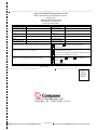
Apex Product Registration Card
Please complete this form and mail or FAX to :
Compsee, Inc.
2500 Port Malabar Blvd. NE
Palm Bay, FL 32905-6065
(321) 723-2895 (FAX)
Model #
Serial #
Company Name
User’s Name
Address
City
State
Country
ZIP
Phone
FAX
E-mail Address
Purchased from
Date Purchased
Please check the box that best describes your company
Individual
Privately -owned Company
Corporation
What is the size of your company?
Under $1 Million in Sales
Greater than $1 Million, less than $10 Million in sales
Greater than $10 Million in sales
What is your application for the Apex III?
Warehousing
Retail
Medical
Government
Service
Other (describe)
You must register this product to receive product support
Reverse Side
Place
Stamp
Here
2500 Port Malabar Blvd. NE
Palm Bay, FL 32905-6065 U.S.A.
Front Side
This Page Intentionally Left Blank
Apex PDT User’s Manual
Warranty Information
APEX PORTABLE DATA COLLECTION
TERMINAL WARRANTY INFORMATION
Note to Purchaser
This warranty and license contains important information on the
servicing and use of your new Apex Portable Data Collection
Terminal (PDT).
Limited Warranty
Compsee, Inc. warrants that for one year from date of purchase, the
Apex Portable Data Collection Terminal shall be free from
significant defects in material and workmanship and that it will
operate satisfactorily under normal conditions of use and service, as
more fully described in this manual or other product specifications
published by Compsee.
Compsee's responsibility under this warranty is limited to repair or
replacement of any part of the terminal which proves to be defective
in normal use and service during the warranty period. Refer to the
Service and Repair section of this manual for the equipment return
procedure.
Program License
Your Apex contains an operating system and BIOS in firmware
which has been programmed by Compsee to enable the terminal to
perform the functions described in the published specifications. Your
purchase of the Apex PDT includes a perpetual, non-exclusive, and
transferable license to use the firmware operating system built into the
Portable Data Collection Terminal.
The operating system can be modified or supplemented with
application programs devised by others, such as a Value Added
Reseller (VAR) from whom you may have purchased the terminal.
All application software programs are the sole responsibility of their
creators. The limited warranty applicable to the Apex does not
include servicing for defects or performance problems caused by any
third party implementation of programs originally manufactured by
Compsee.
COAM30001
Rev. 2.00
8/30/02
i
Apex PDT User’s Manual
Warranty Information
Warranty Disclaimers
These warranties apply only to Apex Portable Data Collection
Terminals purchased directly from Compsee, Inc. or from an
authorized VAR of Compsee products. The warranties are void if
apparent defects were caused by accident, neglect, misuse, alteration,
or unauthorized attempts at adjustment or repair. Warranty service, as
described herein, is the exclusive remedy of the purchaser against
Compsee, Inc. for product defects or any other claim or liability in
connection with the purchase or use of Compsee products.
Warranty Note
THESE WARRANTIES ARE IN LIEU OF ANY
OTHER WARRANTIES, EXPRESS OR IMPLIED,
INCLUDING, BUT NOT LIMITED TO, ANY
IMPLIED WARRANTY OF MERCHANTABILITY
OR FITNESS FOR A PARTICULAR PURPOSE, EVEN
THOUGH COMPSEE, INC. MAY HAVE BEEN
ADVISED OF THE INTENDED USE OF THE
PRODUCTS BY PURCHASER.
Warranty Limitations
Prior to operating the terminal, review the following warranty
limitations. Failure to adhere to the provisions of these limitations
will void the product warranty.
q
DO NOT attempt to open or disassemble the Apex case
except as directed for a specific operation by this or other
Apex manuals (e.g. End Cap Removal). No user serviceable
parts are included in the unit.
q
Charge the Battery Pack only with an approved Compsee
charging device. Use of any charging device other than those
specified by Compsee can potentially damage the Apex or
Battery Pack.
q
DO NOT spray cleaners directly on the keypad or use a
saturated cloth for cleaning the unit. Only a lightly damp cloth
should be used for wiping down the unit.
ii
COAM30001
Rev. 2.00
8/30/02
Apex PDT User’s Manual
Warranty Information
q
DO NOT clean the Apex using alcohol, acetone, mineral
spirits or any other petroleum or alcohol based product.
Damage to the unit can occur.
q
DO NOT leave the unit in the rain or direct sunlight or
immerse the unit in water or any other liquid.
q
Use only Compsee cables for data transfer purposes.
Attachment of other cables may cause damage to the unit
and/or the attachment device.
Recommended Operational Tips
Note:
Failure to heed the following recommendations, while not
voiding the warranty, may result in operational degradation
or program/data loss.
q
DO NOT clean the Laser Window, Display Screen Window,
or IR Window with soap, abrasives, or any alcohol or
petroleum based solution.
q
DO NOT attempt to operate an Apex PDT once it has powered
down due to a low battery condition. When the Battery Pack
is exhausted, leave the exhausted Battery Pack in the Apex
until you can either charge it in place by placing the Apex III
in the Apex III Dock or swap out the Battery Pack with a fully
charged Battery Pack. Information in volatile memory (RAM)
will be preserved since the Apex PDT is configured so that
even with an exhausted Battery Pack enough energy is retained
to maintain the information for an extended period of time.
DO NOT leave the unit WITHOUT a Battery Pack for more
than 5 minutes.
q
The Apex III PDT and Apex IV PDT Battery Packs are of
Nickel Metal Hydride (NiMH) and Lithium – Ion (Li-Ion)
composition respectively. The Battery Packs DO NOT
succumb to memory (hysteresis) loss as do Nickel-cadmium
(Ni-Cd) batteries. Therefore, Apex PDT Battery Packs can be
charged while in any state-of-charge and do not require a full
discharge prior to charging. With the Apex III Battery Pack, it
is still recommended that the Battery Pack be fully discharged
periodically to reset the internal gas gauge circuitry.
COAM30001
Rev. 2.00
8/30/02
iii
Apex PDT User’s Manual
iv
COAM30001
Rev. 2.00
8/30/02
Apex PDT User’s Manual
Table Of Contents
TABLE OF CONTENTS
1
APEX PDT BASICS.....................................................1-1
General User Information ..............................................1-1
Communications Software .......................................1-1
Apex Program Generator..........................................1-2
Using This Manual .......................................................1-2
Apex PDT Characteristics .............................................1-3
Information Entry .........................................................1-5
Scanning (Supported Symbologies) ..........................1-5
Manually Through The Keypad ................................1-6
Systematically Through The Com Port......................1-6
Information Processing .......................................1-6
Unpacking And Inspecting For Damage .........................1-6
Warranty and Safety Notes .......................................1-6
Inspecting the Terminal.......................................1-7
Optional Accessories.....................................................1-8
Apex PDT Set-up and Checkout ....................................1-9
Initial Setup Procedure .............................................1-9
Scanning Techniques ............................................. 1-10
Scanning Difficulties You May Encounter............... 1-11
2
SAFETY......................................................................2-1
Apex PDT Laser Safety (Standard And Very High Density)
....................................................................................2-1
Apex PDT Laser Safety (Long Range Laser) ..................2-3
Battery Pack Safety.......................................................2-5
Product Conformity ......................................................2-7
3
COMPONENT IDENTIFICATION ...............................3-1
General Information ......................................................3-1
Apex PDT Major Component Areas...............................3-1
Front Panel..............................................................3-1
Serial Connection And PC Card Slots .......................3-3
Infrared Interface Window .......................................3-3
Apex III Back Panel.................................................3-4
Apex IV PDT Front And Side View..........................3-5
COAM30001
Rev. 2.00
8/30/02
v
Apex PDT User’s Manual
Table Of Contents
4
UNIT OPERATION......................................................4-1
Front Panel Functional Area Description ........................4-1
Front Panel Key Legends .........................................4-3
Apex PDT Special Functions ....................................4-6
PC Card Installation ......................................................4-7
DIP Switch Positioning .................................................4-7
Battery Charging And Battery Care................................4-8
Apex III Charging Products ......................................4-8
Apex III Dock.....................................................4-8
Apex III External Charger ...................................4-9
Apex IV Charging Products ......................................4-9
Apex III Battery Pack Charging................................4-9
Battery Pack Removal and Installation .................4-9
Charging A Battery Pack In A Charging Slot ......4-10
Apex IV Battery Pack Charging..............................4-12
Battery Pack Removal and Installation ...............4-13
Battery Related Messages ............................................4-13
Battery State Warnings ...........................................4-13
Apex III Call-up Battery Messages..........................4-14
5
HANDLING AND CARE .............................................5-1
General Information ......................................................5-1
Cleaning Instructions.....................................................5-1
How to Care For Your Apex PDT ..................................5-2
Battery Pack Life ..........................................................5-2
6
SUPPORT INFORMATION .........................................6-1
Apex PDT Associated Part Numbers ..............................6-1
Apex PDT Part Number Breakdown .........................6-1
Technical Support .........................................................6-2
Service And Repair .......................................................6-2
Return Material Authorization (RMA) .......................6-3
Unit Specifications ........................................................6-4
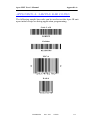
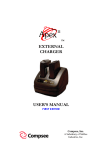
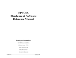
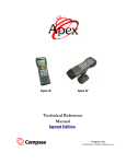
APPENDIX A - SAMPLE BAR CODES ............................. A-1
vi
COAM30001
Rev. 2.00
8/30/02
Apex PDT User’s Manual
1 Apex PDT Basics
1
APEX PDT BASICS
General User Information
This manual provides information necessary to properly operate and
maintain the Apex Portable Data Collection Terminal (PDT).
Contained within this manual is a description of the unit’s hardware
and software; procedures for unpacking and verifying the unit’s
operating functions; operational instructions; Battery Pack charging
and replacement instructions; guidelines for maintaining the Apex
PDT; and other useful information.
Before attempting to understand and operate new equipment, it is
important for the user to gain knowledge by reviewing the available
product information. Whether you are a novice without any
experience in using computers or a confident user with the added
advantage of knowing DOS, this manual contains what you need to
become proficient in operating the Apex PDT. Depending on the
intended operation of your application program(s), additional
resources may be necessary to program the unit, upload and
download data to and from the unit, or print the bar codes that you
would like to scan. The following sections list additional resources
you may require.
Communications Software
The communications software allows the Apex PDT to interface
with a PC, giving you the ability to upload or download data to or
from the unit. Functions include adding, changing, deleting or
viewing data within the unit’s memory.
Your Apex PDT comes with a pre-loaded communications utility
program [dx.exe]. Included on the Compsee Product Support CD is
a Windows ® based counterpart, the Apex PDT Windows Transfer
Utility. Refer to the Apex Technical Reference Manual (TRM) and
to the Help files included with these utilities for additional
information on their use.
In addition, a software communications package such as
HyperTerminal or PROCOMMP LUS loaded on your PC will work
in conjunction with the [dx.exe] utility. The Apex PDT Product
Support CD provided with each unit contains additional
upload/download software programs for your use including
[remdisk.exe] and [remserv.exe] (for use primarily by developers).
COAM30001
Rev. 2.00
8/30/02
1-1
Apex PDT User’s Manual
1 Apex PDT Basics
Apex Program Generator
A Windows based program specifically designed for use with the
Apex PDT, the Apex PDT Program Generator application generates
well structured, modular, and fully commented source code. The
Program Generator's application contains a built-in communications
module that handles data transfers to and from the host PC and the
Apex terminal.
The Compsee part number for the Apex Program Generator is
located in the Parts Section of this manual. The Program Generator
application can be ordered directly from Compsee, Inc. or through
your Value Added Reseller (VAR). Additional product information
and product brochures can be obtained by calling (407) 724-4321 or
(800) 628-3888.
Using This Manual
Typographic conventions followed within this manual:
q
Bold Type is used for headings and important sections
throughout the manual.
q
< > Angular brackets are used to enclose hard keys (keys
whose name and function do not change) located on the Apex
III, such as <FN> and <ENT>.
q
Important points and supplementary information are included
as Notes throughout this manual. Note headings are printed
throughout the manual using bold underlined typeface.
q
When two keys are listed together with the plus (+) sign (e.g.
<FN> + <B>), this indicates that the user should press and
hold the first key while pressing the second key.
q
When specific filenames along with their extension are
addressed in the text they will be denoted by the use of bold
italics and surrounded by brackets (e.g. [remdisk.exe]).
When referring to only the filename and not the extension
(e.g. remdisk) the filename may be shown only in italics.
q
1-2
CAUTION
and WARNING
messages are
provided within this manual, which if not observed, could
result in equipment damage, data loss, or personal injury.
CAUTION and WARNING messages are located within
boxes and with their headings in bold.
COAM30001
Rev. 2.00
8/30/02
Apex PDT User’s Manual
1 Apex PDT Basics
Apex PDT Characteristics
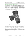
The Apex Portable Data Collection Terminal (PDT) is a state-ofthe-art electronic scanning device. The unit is designed in an easy
to hold, ergonomic format to facilitate source data collection in a
broad range of environments and applications.
The full-functioned capabilities of your Apex PDT allow you to
easily gather bar code or key-entered information, and download
the information for use with your existing business applications.
Your Apex PDT includes the following state-of-the-art features:
q
A 32 bit microprocessor operating @ 33 MHz
q
8 or 16 MB of Flash memory
q
4 MB of On-board RAM
q
A Graphical Display Screen (240 × 160 pixels) with user
activated backlighting
q
Full alphanumeric keypad
q
Wireless LAN capabilities (RF configured Apex PDT)
The Apex PDT can support Batch or Wireless operations via two
internal PC Card slots (capable of simultaneously supporting two
Type I or II devices or a single Type III device). These slots provide
the user with numerous options for connectivity and memory
expansion including, but not limited to network interface adapters,
high speed modems (both wired and wireless), Flash Memory, and
RAM cards.
The Apex III PDT is available with or without an integrated laser
scanner. Available integrated laser options include Standard, Long
Range, Advanced Long Range, or Very High Density. An optional
squeeze-lock connector on the Apex III PDT provides tethered
connectivity (2D Scanner, CCD, wand, etc.) in lieu of an integrated
laser. This option is not available on Apex IV PDT models.
Data transmission to and from the Apex can be accomplished via
the built-in infrared interface or through the optional Serial End
Cap (RS-232) Interface port.
COAM30001
Rev. 2.00
8/30/02
1-3
Apex PDT User’s Manual
1 Apex PDT Basics
Utilizing a DOS based operating system (Datalight
ROM-DOS 6.22), the Apex PDT supports DOS applications,
graphic displays, and existing DOS user software.
An optional Windows based Program Generator can be purchased
to assist the user in implementing most of their basic data collection
type applications.
The basic format for using the Apex PDT with your application
program is laid-out in the following table:
Step
Action/Result
1.
Create the application program on a PC using any DOS based
environment or the optional Apex Program Generator
software.
Upload the programs to the Apex PDT using the IR interface,
the optional Serial End Cap, or the internal RS-232 port.
Power-up the Apex PDT and verify the proper boot sequence
(This may include initiation of your application program
depending on the way your programmer has set the program to
start).
Collect data with the Apex PDT by reading bar codes or
entering data using the front panel keypad.
Download the collected data directly to a mainframe or PC for
processing via one of the following methods:
Ø The IR interface (using the optional Dock)
Ø The optional Serial End Cap
Ø A wireless LAN (RF configured Apex PDT required)
Ø The internal RS-232 port.
2.
3.
4.
5.
6.
Use the collected data in existing application programs
including standard PC spreadsheet or database programs.
Table 1-1: Apex PDT Basic Use
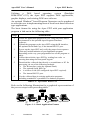
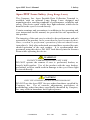
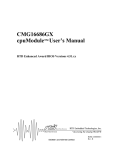
Refer to the following illustration for a graphical representation of
the process steps in the preceding table.
SCAN
PROGRAM
UPLOAD
DOWNLOAD
PROCESS
Figure 1-1: Basic Application Format
1-4
COAM30001
Rev. 2.00
8/30/02
Apex PDT User’s Manual
1 Apex PDT Basics
Information Entry
As shown in Figure 1-1, the Apex PDT can be used as a remote data
collection device using a data collection program developed by your
application programmer. Once the data collection program has been
loaded into the unit (and started during booting or manually
executed after boot-up), data can be collected with the Apex PDT.
Three ways of collecting data with the Apex PDT are described
below.
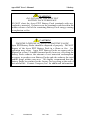
Scanning (Supported Symbologies)
The Apex PDT is capable of reading and automatically
discriminating between most of the major bar code symbologies in
use today as defined by the Automatic Identification Manufacturers,
Inc. (AIM) specifications. The bar code formats incorporated into
your Apex PDT include the following:
q
q
q
q
q
q
q
q
Codabar
Code 11
Code 39 (standard)
Code 39 (full ASCII)
Code 93
Code 128
EAN 8/13
Interleaved 2 of 5
q
q
q
q
q
q
q
q
Identicode 2 of 5
Industrial 2 of 5
JAN 8/13
Matrix 2 of 5
MSI Plessey
PDF (via serial input only)
UPC-A/E
UPC/EAN (with 2 or 5
character supplemental)
Additional scanning instructions and considerations are provided
later in this chapter under the Checkout Procedure topic.
COAM30001
Rev. 2.00
8/30/02
1-5
Apex PDT User’s Manual
1 Apex PDT Basics
Manually Through The Keypad
During the data collection process, the Apex PDT may prompt you
for additional information. By using the front panel keypad, the
operator can enter additional information such as quantity, price,
location, etc.
Note:
If the Apex PDT prompts you for additional information
regarding the data you are collecting, your application
programmer has previously defined your Apex unit to
work in this manner. The Apex PDT will not operate in
this fashion until your company's application program has
been loaded.
Systematically Through The Com Port
Information transfer for the Apex PDT can also be uploaded or
downloaded from the host computer system to the unit through the
IR interface (using the optional Dock), the Serial End Cap, a
Wireless LAN (requires an RF configured Apex PDT), or the
Internal RS-232 port. It should be noted that only one of these
methods can be used at a time.
Information Processing
The Apex PDT allows the operator to store, process, and transmit
acquired information. Application programs written to work in a
DOS operating environment allow the unit to be customized for
practically any portable data collection requirements. The built-in
IR and RS-232 Serial interfaces provide for data communication
transfer with other data processing equipment. Additionally,
purchasing an RF Configured Apex PDT (or upgrading a standard
Apex PDT to RF capabilities) allows the user to transfer collected
data via a Wireless LAN.
Unpacking And Inspecting For Damage
Warranty and Safety Notes
Prior to operating the Apex PDT, it is recommended that the user
review the Warranty Limitations and Safety Precautions cove red
within this manual. When operating the Apex PDT with an
integrated laser, failure to heed the recommendations and
precautions described may result in exposure to hazardous laser
radiation and possibly void the unit warranty.
1-6
COAM30001
Rev. 2.00
8/30/02
Apex PDT User’s Manual
1 Apex PDT Basics
Inspecting the Terminal
The Apex PDT is specially packaged to protect the unit during
shipping and handling. Retain the shipping container and all
packing materials for use in the event a return is necessary. These
items should be used when returning the unit for service or repairs.
If a new container is needed, contact Compsee at (407) 724-4321 or
(800) 768-5248. Before contacting Compsee or one of our Value
Added Resellers, carefully read the Technical Support section of
this manual.
Upon receipt of your Apex PDT, immediately inspect the package
contents for possible shipping damage. In the unlikely event that
anything is damaged or missing, perform the following:
1.
Return the package contents to their original carton, along
with packing materials, and place them in the proper
configuration.
2.
Notify the delivering carrier of damages and request
immediate inspection.
3.
Contact the shipper.
4.
Send a letter of intent to file a claim to the delivering carrier
within 72 hours from the date of delivery.
5.
Send a copy of the letter to the shipper. Only the consignee
(the receiving party) can file a claim against the carrier for
concealed damages.
6.
Unpack the Apex Portable Data Collection Terminal and all
the accessories contained in the carton.
7.
Assure that you have received all of the components listed
on the enclosed packing slip.
COAM30001
Rev. 2.00
8/30/02
1-7
Apex PDT User’s Manual
1 Apex PDT Basics
Optional Accessories
The following items are available as optional accessories to the
Apex III PDT (refer to the parts section of this manual for specific
part numbers):
q
Additional Battery Packs
q
Serial End Cap – Allows an RS-232 serial connection without
End Cap removal.
q
Serial Interface Cable (Serial End Cap to DB-9)
q
External Charger – Allows simultaneous charging of up to two
Apex III Battery Packs
q
Apex III Dock – A docking station incorporating Infrared (IR)
coupling, slip-in charging capabilities, and an additional slot
for charging a spare Apex III Battery Pack. The unit
incorporates wall or desk mounting capabilities.
q
Additional Power Supplies (with or without an AC line cord)
q
Vehicle Lighter Adapter – Cigarette lighter adapter cable for
connecting Dock or External Charger Power supply to a 12
VDC vehicle power source.
q
Soft-Side Case – A form fitted cloth cover with a built-in hand
strap that provides additional protection for your Apex PDT.
q
Soft-Side Holster – A custom pouch with a built-in belt holder
that allows the Apex PDT to be worn on your hip for easy
carrying and accessibility.
q
Apex Program Generator Software – Assists an application
developer in writing custom Apex PDT Application programs
(includes file transfer capabilities).
q
Compsee Product Support CD (additional copies)
1-8
COAM30001
Rev. 2.00
8/30/02
Apex PDT User’s Manual
1 Apex PDT Basics
Apex PDT Set-up and Checkout
The Apex Portable Data Collection Terminal is a sophisticated
electronic piece of equipment. To ensure proper operation, superior
performance, and a long service life we recommend that you follow
the instructions put forth in this User’s Manual. The following
information is a guideline to be used during initial checkout of the
unit.
Note:
Your Apex PDT unit comes with one Battery Pack, which
was fully charged at the factory.
As with most
rechargeable batteries, depending on when you received
your unit and the date the Battery Pack was initially
charged, the Battery Pack may no longer be in the fully
charged state.
Initial Setup Procedure
1.
It is recommended that the user read the entire Apex PDT
User’s Manual before proceeding with the Initial Setup
procedure. This is especially true of Sections 2 through 4,
which include the Safety and Operational information.
2.
Insert the Apex PDT Battery Pack into the Battery Bay as per
the Battery Charging section of this manual.
3.
Press the red <Power> button on the bottom of the Apex PDT
front panel.
4.
Wait approximately 1.5 seconds, than verify the screen
displays the boot sequence. e.g. BIOS information followed
by an audible beep, message “Starting ROM-DOS…”,
configuration information, etc.
5.
If your unit’s [autoexec.bat] file automatically loads a
customer specific application program (setup by your IT
department), the screen will display a message referring to
the specific application.
6.
If no application program has been loaded, or one is loaded,
and it is not configured to start automatically by the
[autoexec.bat] file, then the screen will stop with the Cprompt:
C:\>
COAM30001
Rev. 2.00
8/30/02
1-9
Apex PDT User’s Manual
Note:
1 Apex PDT Basics
Your Apex PDT comes with a basic scanning program
preloaded by Compsee, Inc. At this time the unit should
be ready to scan bar codes. Refer to the following section
for detailed scanning techniques before performing the
following step.
CAUTION!
VIEWING SCANNER BEAM DIRECTLY
IS NOT RECOMMENDED
The scanner contained in the Compsee, Inc. Apex Portable Data
Collection Terminal is a Class II laser device. It is a low power
laser. Momentary viewing of the beam will not cause retinal
damage. You are strongly cautioned against any direct viewing of
the scanner output.
7.
Test the unit by pressing the <SCAN> button and reading the
bar code on the back cover of this manual or the bar code
examples furnished in Appendix A.
Scanning Techniques
Following the scanning techniques presented below will ensure
accurate and error-free scanning of most bar codes. Please be
aware that worn, dirty, torn, or damaged bar code labels or imprints
can adversely affect the scanning process and cause errors in your
data.
Note:
DO NOT aim the laser so the beam is exactly
perpendicular to the bar code symbol. Symbols printed on
a glossy surface can cause a reflection that can interfere
with the scan read. Pointing the laser so the beam
intersects the bar code at an angle will reduce the chance
of the reflection interference.
q
To begin the scanning process, place the Apex PDT so the
laser window is slightly above or below the bar code.
q
Make sure that the Apex PDT is a sufficient distance from the
bar code so the laser extends beyond the outermost edges of
the code. This will ensure that the entire code is “read” and
the read is good.
1-10
COAM30001
Rev. 2.00
8/30/02
Apex PDT User’s Manual
1 Apex PDT Basics
q
Press and hold the <SCAN> button on the Apex PDT front
panel, then smoothly and evenly pass the laser completely
over the bar code. The yellow Scan LED will illuminate.
q
After successfully scanning a bar code and a good “read”
occurs, the green Decode LED will illuminate and an audible
beep will be heard.
q
If the bar code does not read correctly try again. After you
have performed the operation a few times it will become
second nature.
Scanning Difficulties You May Encounter
The following items can cause possible problems when attempting
to scan a bar code:
Note:
For specific details on enabling bar code symbologies used
by your unit, refer to the Apex PDT Technical Reference
Manual).
q
The bar code symbology type being read must be supported
(see p. 1-5) and enabled on your Apex PDT.
q
The bar code character number must match the same number
of characters as programmed into the Apex PDT.
q
Bar code labels should be clean (not smeared) and complete
(not torn or damaged).
q
High gloss bar code labels can cause reflections, which
interfere with a proper read (holding the unit at a greater
angle – non perpendicular will help prevent this from
occurring).
COAM30001
Rev. 2.00
8/30/02
1-11
Apex PDT User’s Manual
1-12
COAM30001
1 Apex PDT Basics
Rev. 2.00
8/30/02
Apex PDT User’s Manual
2
2 Safety
SAFETY
Apex PDT Laser Safety
(Standard And Very High Density)
The Apex Portable Data Collection Terminal is equipped with a
light emitting laser device. The unit has been designed and
manufactured to exacting standards for performance, reliability and
safety. This product emits visible laser radiation, which can be
harmful to the eyes if viewed directly.
Certain warnings and precautions, in addition to the operating and
care instructions in this manual, are provided for safe operation of
this product.
The integrity of the unit case is critical to the performance and safe
operation of the product. In the event that the case becomes broken,
loose, cracked, or perforated, operation of the unit should cease
immediately. Only after authorized personnel have repaired the
unit, should operation of the unit resume.
It is recommended that personnel using this device DO NOT look
directly into the Scanner Beam while operating the device.
WARNING!
DO NOT TAMPER WITH THE UNIT CASE
DO NOT operate the scanner if case is perforated, broken, or
loosely held together. Use of the product with the case broken,
perforated, or loose could result in damage to the eyes if laser light
is viewed directly.
CAUTION!
ONLY USE COMPSEE APPROVED METHODOLOGY
DO NOT use the Apex PDT for uses other than those specified by
Compsee, Inc. Use of controls, adjustments, procedures, or
methodology other than those specifically identified by Compsee,
Inc. may result in hazardous laser light exposure.
COAM30001
Rev. 2.00
8/30/02
2-1
Apex PDT User’s Manual
2 Safety
CAUTION!
VIEWING SCANNER BEAM DIRECTLY
IS NOT RECOMMENDED
The scanner contained in the Compsee, Inc. Apex Portable Data
Collection Terminal is a Class II laser device. It is a low power
laser. Momentary viewing of the beam will not cause retinal
damage. You are strongly cautioned against any direct viewing of
the scanner output.
WARNING!
FAILURE TO ADHERE TO WARNINGS,
CAUTIONS, AND APPROVED PROCEDURES COULD
RESULT IN EXPOSURE TO HARMFUL,
VISIBLE LIGHT RADIATION
The following Caution Label is mounted on the Apex Portable
Data Collection Terminal to caution users of the possible
effects of laser radiation.
Apex III Caution Label
Apex IV Caution Label
The following exposure label is a reproduction of the label mounted
inside the Apex Portable Data Collection Terminal.
CAUTION – Laser Light when open.
DO NOT STARE INTO BEAM
2-2
COAM30001
Rev. 2.00
8/30/02
Apex PDT User’s Manual
2 Safety
Apex PDT Laser Safety (Long Range Laser)
The Compsee, Inc. Apex Portable Data Collection Terminal is
available with an optional Long Range Laser designed and
manufactured to exacting standards of performance, reliability and
safety. This device emits visible laser light radiation, which can be
harmful to the eyes if viewed directly.
Certain warnings and precautions, in addition to the operating and
care instructions in this manual, are provided for safe operation of
this product.
The integrity of the unit case is critical to the performance and safe
operation of the product. In the event that the case becomes broken,
loose, cracked, or perforated, operation of the unit should cease
immediately. Only after authorized personnel have repaired the unit,
should operation of the unit resume. It is recommended that
personnel using this device DO NOT look directly into the Scanner
Beam while operating the device.
WARNING!
DO NOT TAMPER WITH THE UNIT CASE
DO NOT operate the scanner if case is perforated, broken, or
loosely held together. Use of the product with the case broken,
perforated, or loose could result in damage to the eyes if laser light
is viewed directly.
CAUTION!
ONLY USE COMPSEE APPROVED METHODOLOGY
DO NOT use the Apex PDT for uses other than those specified by
Compsee, Inc. Use of controls, adjustments, procedures, or
methodology other than those specifically identified by Compsee,
Inc. may result in hazardous laser light exposure.
COAM30001
Rev. 2.00
8/30/02
2-3
Apex PDT User’s Manual
2 Safety
DANGER!
THE LASER SCANNER CONTAINED IN THIS COMPSEE,
INC. APEX PORTABLE DATA COLLECTION TERMINAL IS
A CLASS IIIA LASER. ANY DIRECT VIEWING OF THE
SCANNER BEAM IN THE AIMING MODE SHOULD
BE AVOIDED.
The following Danger Label is mounted on the Apex Portable
Data Collection Terminal to warn users of the possible effects
of laser radiation.
Apex III Danger Label
Apex IV Caution Label
The following exposure label is a reproduction of the label mounted
inside the Apex Portable Data Collection Terminal.
DANGER – Laser Light when open.
AVOID DIRECT EYE EXPOSURE
2-4
COAM30001
Rev. 2.00
8/30/02
Apex PDT User’s Manual
2 Safety
Battery Pack Safety
WARNING!
ONLY USE COMPSEE, INC. APPROVED CHARGERS!
Only charge the Apex III Battery Packs in the Apex III Dock or the
Apex III External Charger. DO NOT use chargers from other
manufacturers. The Battery Pack warranty will be voided and
Battery Pack Damage could occur.
CAUTION!
PLACE THE UNIT IN SUSPEND IF THE CHANGE
BATTERY MESSAGE IS RECEIVED!
We recommend that the user place the unit in “Suspend” and
change to a fully charged Battery Pack or recharge the installed
Battery Pack after receiving the “Change Battery” message. After
this operation, pressing the “Suspend” button again wi ll return the
unit to the position of the last performed operation. When the
“Battery Critical” alarm is received, the unit will shutdown and can
NOT be restarted until the Battery Pack is replaced with a charged
Battery Pack or the installed pack is recharged.
WARNING!
DO NOT OPERATE THE APEX PDT ONCE IT HAS POWERED
DOWN DUE TO A LOW BATTERY CONDITION!
DO NOT attempt to operate the Apex PDT once it has powered
down due to a low battery condition. When the Battery Pack is
exhausted, leave the exhausted Battery Pack in the Apex PDT until
you can either charge or swap the Battery Pack with a charged
Battery Pack. Information in volatile memory (RAM) will be
preserved since the Apex PDT is configured so that even with an
exhausted Battery Pack enough energy is retained to maintain the
information for an extended period of time. DO NOT leave the unit
WITHOUT a Battery Pack for more than 5 minutes.
COAM30001
Rev. 2.00
8/30/02
2-5
Apex PDT User’s Manual
2 Safety
WARNING!
DO NOT SHORT THE APEX PDT
BATTERY PACK TERMINALS!
DO NOT short the Apex PDT Battery Pack terminals with any
conductive material. A short across the terminals could result in the
sudden release of all of the remaining Battery Pack energy causing
an explosion or fire.
CAUTION!
PROPERLY DISPOSE OF APEX PDT BATTERY PACKS!
Apex PDT Battery Packs should be disposed of properly. DO NOT
dispose of the Apex PDT Battery Pack in a flame or fire. An
explosion may occur. Apex PDT Battery Packs are approved for
disposal in a class 2 Landfill (normal trash); however, recycling the
Battery Packs reduces the amount of raw materials consumption
necessary to produce new Battery Packs and also reduces the total
landfill usage within your area. We highly recommend that the
Battery Packs be returned to the factory for recycling at the end of
their useful life. Contact Compsee, Inc. for additional information.
2-6
COAM30001
Rev. 2.00
8/30/02
Apex PDT User’s Manual
2 Safety
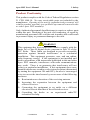
Product Conformity
This product complies with the Code of Federal Regulations section
21 CFR 1040.10. No user serviceable parts are included in the
manufacture. Opening of the unit by unauthorized personnel will
void the product warranty (except End Cap removal as noted in this
or other Apex PDT manuals).
Only Authorized personnel should attempt to repair or replace parts
within this unit. Breaking of the unit seal, tampering, or repair by
unauthorized personnel will void the unit warranty and could result
in personnel injury or permanent damage to the unit.
WARNING!
This equipment has been tested and found to comply with the
limits for a Class B digital device pursuant to Part 15 of the
FCC Rules. These limits are designed to provide reasonable
protection against harmful interference in a residential
installation. This equipment generates, uses, and can radiate
radio frequency energy. If the equipment is not installed and
used in accordance with instructions published in this and other
Apex PDT manuals, interference with radio communications
may result. There is no guarantee that interference will not
occur in a particular installation. If this equipment does cause
harmful interference to radio or television reception (determined
by turning the equipment ON and OFF), the user is encouraged
to try to correct the interference by one or more of the following
measures:
q Reorientation or relocation of the receiving antenna.
q Increasing the separation between the equipment and
affected receiver.
q Connecting the equipment to an outlet on a different
electrical circuit than that of the affected receiver.
q Consulting the dealer or an experienced radio/TV
technician for help.
COAM30001
Rev. 2.00
8/30/02
2-7
Apex PDT User’s Manual
2-8
COAM30001
Rev. 2.00
8/30/02
Apex PDT User’s Manual
3
3 Component Identification
COMPONENT IDENTIFICATION
General Information
The Apex Portable Data Collection Terminal (PDT) uses a soft
touch keypad design, which emulates all of the major functions
found on a standard PC keyboard. Computer and calculator type
features incorporated into the front keypad area allow the operator
or application programmer to enter data, transmit data, or program
the unit in the same manner as if they were operating a standard PC.
With its advanced technology, the Apex PDT is fully programmable
and can be utilized for practically any data collection purpose.
Apex PDT Major Component Areas
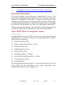
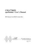
Front Panel
Incorporated into the Apex PDT front panel are the following major
components to assist the operator in performing their specific
functional requirements:
q
Display Screen (LCD)
q
Power Control Button (Key - Red)
q
Numerical Key Area
q
Alphabetical Key Area
q
Function Key Area
q
Shift Button (Key - Yellow)
q
Second Function Button (Key - Green)
q
Cursor Buttons (Keys)
q
LED Indicators
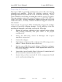
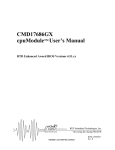
The following illustration (Figure 3-1) shows the frontal view of the
Apex PDT and the orientation of the major functional areas
incorporated into the unit’s keypad area:
COAM30001
Rev. 2.00
8/30/02
3-1
Apex PDT User’s Manual
LED
INDICATOR
(GREEN)
3 Component Identification
DECODE
LED
INDICATOR
(YELLOW)
SCAN
DISPLAY
SCREEN
F5 F9
FUNCTION
BUTTONS
F1
PG UP
HOME
END
PG DN
F2
CURSOR
BUTTONS
ENTER
BUTTON
ENT
SCAN
SCAN
BUTTON
1
!
<
@
,
%
&
|
*
>
\
)
4
$
7
A
~
F
2
5
Bkgd
3
_
#
-
^
+
(
B
Batt
0
SPACE
C
Con
G
H
L
M
'
D
Con
I
E
ESCape
J
Tab
N
Bklt
ALPHABETICAL
KEYPAD
AREA
O
/
Q
R
S
?
{
}
V
W
SHIFT
"
=
P
U
;
9
Prtsc
Break
:
6
8
`
K
SHIFT
BUTTON
(YELLOW)
FUNCTION
BUTTONS
F3
ENT
ENTER
BUTTON
NUMERICAL
KEYPAD
AREA
F8 F12
F7 F11 F4
F6 F10
Vol
ALT
X
[
]
Z
CTRL
T
Date
Y
Pause
FUNCTION
BUTTON
(GREEN)
FN
CAPS
DEL
BKSP
INS
DELETE
BUTTON
END CAP
BACKSPACE
BUTTON
POWER BUTTON
Figure 3-1: Apex PDT Front Panel
Functional Area General Description
3-2
COAM30001
Rev. 2.00
8/30/02
Apex PDT User’s Manual
3 Component Identification
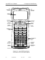
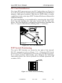
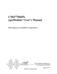
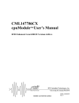
Serial Connection And PC Card Slots
The Apex PDT comes equipped with an RS-232 Serial connector
for uploading and downloading information from or to a PC or
other Serial device. The removable bottom End Cap exposes the
PC Card slots (2), the RS-232 8-pin connector, and the operational
DIP switches.
SLOT"0"
SLOT"1"
PCMCIA
CARD
SLOT
AREA
RS-232
SERIAL
CONNECTOR
DIP
SWITCHES
Figure 3-2: Apex With End Cap Removed
Note: Serial communication using the RS-232 Serial connection
can be half or full duplex. Serial communication using the
IR Window must be half-duplex.
An optional Serial End Cap may be purchased and installed
allowing a serial connection to be made without the End Cap being
removed (replaces the standard End Cap). See the Optional
Accessories section of this manual or contact your authorized Value
Added Reseller (VAR) to find out more about this product.
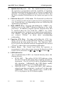
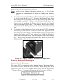
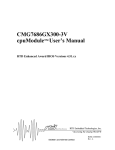
Infrared Interface Window
An Infrared (IR) window located at the top of the Apex PDT (see
Figure 3-3) provides a means of transmitting data via infrared light
pulses to or from the optional Dock. Refer to the Optional
Accessories section of this manual and contact Compsee, Inc. or
your authorized Value Added Reseller (VAR) to find out more
about this product.
LASER WINDOW/
WAND PORT
INFRARED
WINDOW
NOTE: APEX IV SIMILARLY
CONFIGURED
Figure 3-3: Apex III Infrared (IR) Window
COAM30001
Rev. 2.00
8/30/02
3-3
Apex PDT User’s Manual
3 Component Identification
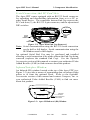
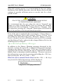
Apex III Back Panel
The Apex III Back Panel is constructed of stylish yet ergonomically
designed high impact plastic, contoured and textured to give the
user a firm comfortable feel when holding the unit.
The Apex III Back Panel contains provisions for mounting the
Apex III Battery Pack in a non-protruding format that conforms to
the overall contour of the unit. This mounting format allows the
battery charging terminals to be exposed for slip-in charging when
the unit is placed into the optional Dock.
LASER WINDOW/
WAND PORT
LASER
WARNING
LABEL
BATTERY
RELEASE
TAB
BATTERY
PACK
BATTERY
CHARGING
TERMINALS
Figure 3-4: Apex III Back Panel Components
3-4
COAM30001
Rev. 2.00
8/30/02
Apex PDT User’s Manual
3 Component Identification
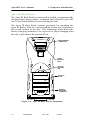
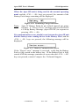
Apex IV PDT Front And Side View
The Apex IV PDT has the same front panel configuration as that of
the Apex III PDT. A comfortably styled handle integrated into the
rear of the unit allows for the user to easily handle the unit while
scanning items or entering data manually. All operations and
functions that can be performed by the Apex III and Apex IV PDT
models are the same unless specified within this manual or the
Apex PDT Technical Reference Manual.
Figure 3-5: Apex IV Front And Side View
To enhance weight distribution, functionality, and ease of use, the
Battery Pack compartment has been incorporated into the base of
the handle. Integrated protective rubber guards surrounding the top
and bottom of the front panel and the base of the handle have
augmented the overall durability and functionality of the unit. In
addition to providing the Apex IV PDT with added drop protectionl,
the above described features allow the unit to be placed in various
positions for easier readability or in preparation for the next
operation.
COAM30001
Rev. 2.00
8/30/02
3-5
Apex PDT User’s Manual
3-6
COAM30001
3 Component Identification
Rev. 2.00
8/30/02
Apex PDT User’s Manual
4
4 Unit Operation
UNIT OPERATION
Front Panel Functional Area Description
Note:
Key functions described herein are for those functions
dedicated by factory hardware and software. Your
application programmer may program additional key
functions into the unit. If applicable, refer to your specific
application program guidelines for these functions.
q
Display Screen (LCD): The LCD Display Screen, is a fully
programmable graphics LCD with a 240 × 160 pixel display.
The screen displays characters relating to either the scanned
input or those keyed in via the front panel keypad. Messaging
from the current running application program as well as
messages informing the operator of the unit’s condition
(“Change Battery”, etc.) are displayed either by the program
itself or when the correct function keys are depressed.
q
Power Control Key: The Power Control key turns the unit
ON or places the unit in the Suspend mode. When initially
pressed, the key causes the unit to turn ON and perform a
“Cold Boot” (runs through the initialization sequence and may
automatically start your specific application program if setup
by your application developer).
When pressed a second time, the Power key places the Apex
PDT in the Suspend mode (a low power mode where the
display screen turns off, but information remains stored in
memory). Pressing the Power key again when in the Suspend
mode returns the unit to normal operation.
To completely shut the unit OFF, press and hold the FN key,
then press the Power key (<FN> + <Power>).
q
Numerical Keys: The Numerical keys provide the operator or
programmer the capability of inputting numerical information
into the unit’s memory or application program field. Pressing
a number key inserts the number into the display field and
moves the cursor one space to the right.
COAM30001
Rev. 2.00
8/30/02
4-1
Apex PDT User’s Manual
q
q
q
q
q
q
4-2
4 Unit Operation
Alphabetical Keys (A – Z): The Alphabetical keys provide
the operator or programmer with the capability of inputting
alphabetical information into the unit’s memory or application
program. Pressing an alphabetical key inserts the letter into
the active display field and moves the cursor one space to the
right.
Function Keys (F1 – F12) Area: The Function keys allow the
user to call up specific menus or macros for the program being
run. Functions may vary depending on the use selected by the
application programmer.
Shift (SHIFT) Key: Pressing and holding the <SHIFT> key
allows access to the SHIFT character function of the front
panel keys. In addition, program specific functions may also
be initiated when the user holds the <SHIFT> key while
pressing another key (setup by your application programmer).
The <SHIFT> key and shift function character designations
are colored “Yellow” to show their corresponding
relationship.
Function (FN) Key: Pressing and holding the <FN> key
allows access to the second function actions or characters
displayed on the front panel key area. The Function <FN>
key as well as the function character designations are colored
“Green” to show their corresponding relationship.
Cursor Keys: The Cursor keys allow the operator or
programmer to move the screen cursor in the direction of the
cursor arrow pressed (Left , Up , Right , or Down ).
LED Indicators:
Two Communication LED’s are located directly above the
Display Screen.
Ø
SCAN LED – The yellow SCAN LED indicates when
the unit is in the SCAN mode and a scanning operation is
in progress. The SCAN LED will be illuminated during
this operation. Additionally, the LED blinks rapidly
when data is being received (via IR or RS-232).
Ø
DECODE LED – The green DECODE LED indicates
when the unit has performed a “good read” of a bar code.
Additionally, when a data transmission ( via IR or RS232) is in progress the LED blinks rapidly.
COAM30001
Rev. 2.00
8/30/02
Apex PDT User’s Manual
q
q
q
q
q
q
q
4 Unit Operation
SCAN Key: Pressing the <SCAN> key energizes the Apex
PDT laser when a scan application program has loaded. This
allows the operator to scan bar codes.
Enter (ENT) Key: The <ENT> key performs the same
function as an enter key on a PC or calculator. The key
enters the information into the processor or application
program in the active field.
Control (CTRL) & Alternate (ALT) Keys:
The <CTRL> and <ALT> keys perform just as on a normal
PC, providing auxiliary functions depending on the
application program which has been loaded.
Backspace (BKSP) Key: Pressing the <BKSP> key causes
the cursor to move left and delete a character to the left of the
cursor’s original position. Pressing <FN> + <BKSP> acts the
same as the Insert key on a PC keyboard, toggling whether
the pressing of any key inserts a character or overwrites any
existing character to the right of the cursor.
Delete (DEL) Ke y: Just as on a normal PC, the <DEL> key
deletes characters to the right of the cursor location. Each
depression of the key deletes one character.
CTRL+ALT+DEL Keys: Just as on a normal PC, pressing
the <CTRL> + <ALT> + <DEL> keys at the same time,
causes the Apex PDT CPU (Central Processing Unit) to
perform a warm boot. Any data stored in the system RAM
memory will be lost.
SCAN + POWER Keys: Pressing the <SCAN> key and the
<Power> key at the same time causes the unit to perform a
cold boot. During rebooting the display screen will initially
go blank for approx. 1.5 seconds.
Front Panel Key Legends
The following tables describe the key functions of the various front
panel keys incorporated into the Apex PDT:
Symbol/Color
Symbol
Main
Function
Black
F1
F2
F3
F4
SHIFT
Function
Yellow
F5
F6
F7
F8
2 nd (FN)
Function
Green
F9
F10
F11
F12
Table 4-1: Function Key Legend
COAM30001
Rev. 2.00
8/30/02
4-3
Apex PDT User’s Manual
4 Unit Operation
Main
Function
SHIFT
Function
2nd (FN)
Function
Black
Yellow
Green
None
None
None
None
Home
Page Up
End
Page Down
Symbol/
Color
Symbol
Table 4-2: Cursor Key Legend
Main
Function
SHIFT
Function
2nd (FN)
Function
Black
Yellow
Green
Symbol/
Color
0
)
=
1
!
<
2
@
_
3
#
:
4
$
,
Symbol
5
%
6
^
;
7
&
|
8
*
+
9
(
“
SPACE
none
‘
Ÿ
>
/
Table 4-3: Numerical Key Legend
Symbol/
Color
Symbol
Main
Function
SHIFT
Function
2nd (FN) Function
Black
Yellow
Green
A, a
B, b
C, c
D, d
E, e
F, f
~
Changes
letter case,
when held
while
pushing the
letter key
Batt
(Battery condition)
Con
(Contrast ↑ )
Con
(Contrast ↓ )
ESCape
`
Table 4-4: Alphabetical Key Legend
4-4
COAM30001
Rev. 2.00
8/30/02
Apex PDT User’s Manual
Symbol/
Color
Main
Function
Black
SHIFT
Function
Yellow
2nd (FN) Function
Green
G, g
H, h
I, i
J, j
None
None
Tab
None
K, k
Bkgd
(screen background)
L, l
M, m
N, n
Symbol
4 Unit Operation
O, o
P, p
Q, q
R, r
Changes
letter
case,
when
held
while
pushing
the letter
key
Bklt
None
None
/
Prtsc (Print Screen)
?
{
S, s
T, t
(backlighting)
}
Date
U, u
(date & time)
Break
V, v
Vol
(Volume)
W, w
[
X, x
]
Y, y
Pause
Z, z
None
DEL
None
None
INS
BKSP
None
Table 4-4: Alphabetical Key Legend continued
COAM30001
Rev. 2.00
8/30/02
4-5
Apex PDT User’s Manual
4 Unit Operation
Apex PDT Special Functions
Your Apex Portable Data Collection Terminal includes several
special features that operate as follows:
q
Battery Status Indication: The Battery Pack status can be
called up at any time by pressing and holding the <FN> key
and then the <B> key. A Battery Status display window will
appear on the screen (refer to Call-up Battery Message
section, p. 4-14).
q
Contrast Adjust: The display screen contrast can be
manually adjusted by the operator. To increase the contrast,
press and hold the <FN> key and then the <C> key. To
decrease the screen contrast, press and hold the <FN> key
and then the <D> key.
q
Screen Background: The display screen view can be
inverted from normal (black on white) by pressing and
holding the <FN> key and then pressing the <K> key.
Performing the operation again toggles the display.
q
Backlighting: For low light level areas, the display screen
includes a Backlight. Pressing and holding the <FN> key
and then pressing the <L> key causes the light to illuminate.
Performing the operation again toggles this function.
q
Date and Time Display: The operator can call up a display
window showing the Date and Time simply by pressing and
holding the <FN> key and the <T> key. Releasing the keys
causes the display to return to normal.
q
Volume Control: The Apex PDT includes a fully functional
speaker and volume control adjustment for applications
using sound. By pressing and holding the <FN> key and
then the <V> key, the unit’s volume can be cycled through
OFF-LOW-MED-HIGH.
q
CAPS Lock: To set the CAPS lock, press and hold the
<FN> key, then press the <SHIFT> key. Repeating the
operation removes the CAPS lock.
Figure 4-1: Date And Time Display
4-6
COAM30001
Rev. 2.00
8/30/02
Apex PDT User’s Manual
4 Unit Operation
PC Card Installation
The Apex PDT can accept up to two PC Cards (either two Type I or
II, or one Type III) for various purposes including network interface
adapters, high speed modems, flash drives, RAM disks, or audio
capabilities (refer to the Apex PDT Technical Reference Manual for
additional details).
PC Card installation is accomplished by removing the Apex PDT
End Cap and installing the card pins inward and the label side
down. Note that hardware configuration requirements demand that
Slot “0” (top) be filled before utilizing Slot “1” (bottom).
CARD EJECTION
BUTTONS
SLOT"0"
SLOT"1"
INSERT
CARD
LABEL
SIDE
DOWN
End Cap Screws, 4 - 40 x 3/16"
PN 0220075
Figure 4-2: PC Card Installation
DIP Switch Positioning
The unit’s DIP Switches are located to the right of the internal
RS-232 connection (refer to Figure 3-2). Changing DIP Switch
position is NOT recommended or necessary for normal operation.
If a switch position inadvertently gets changed, the following
illustration shows the correct position for normal operation (all
switches OFF).
1
ON
2
3
4
Switch
(white)
Figure 4-3: DIP Switch Positioning
COAM30001
Rev. 2.00
8/30/02
4-7
Apex PDT User’s Manual
4 Unit Operation
Battery Charging And Battery Care
The Apex III PDT comes with one Nickel Metal Hydride (NiMH)
Battery Pack. The Battery Pack can be fully charged from the
completely discharged state within 2 hours through the use of the
optional Apex III Dock or External Charger.
The Apex IV PDT utilizes a Lithium-Ion (Li-Ion) Battery Pack.
The Apex IV Battery Pack is charged by removing the Battery Pack
from the unit and placing it in the Lenmar ® BCV636 Battery
Charger. Colored LED’s indicate when the Battery Pack is
charging or fully charged.
The Apex III Dock and Apex PDT Battery Chargers can be
purchased separately, allowing for greater flexibility with the user’s
requirements. The following manual sections provide a brief
description of these units and their capabilities.
Note:
Since Apex PDT Battery Packs are of NiMH or Li-Ion
composition, they DO NOT succumb to memory
(hysteresis) loss like Nickel-Cadmium (Ni-Cd) batteries.
Apex III Battery Packs can therefore be charged while in
any state-of-charge and do not require full discharge prior
to charging; however, it is still recommended that the
Battery Pack be fully discharged periodically to reset the
internal gas gauge circuitry.
Apex III Charging Products
Apex III Dock
The Apex III Dock is a docking station incorporating space saving
features such as an IR interface, slip-in charging capabilities, and a
spare Battery Pack charging slot. The unit can be placed on a flat
surface or conveniently wall mounted depending on your particular
requirements.
With these features the Apex III Battery Pack can be charged
without removal from the unit, and communications to the Apex III
can be conducted while mounted in the Dock. By using the
incorporated charging slot, a spare Battery Pack can be
simultaneously charged ensuring a fully charged spare Battery Pack
at all times. Refer to the Apex III Dock Illustration Figure 4-6.
4-8
COAM30001
Rev. 2.00
8/30/02
Apex PDT User’s Manual
4 Unit Operation
Apex III External Charger
The Apex III External Charger provides simultaneous charging for
up to two Apex III Battery Packs. With its small size due to the
piggyback design, this unit is convenient for placement in
warehouse areas or areas where space is at a premium. Like the
Apex III Dock, the External Charger can be either desk or wall
mounted for convenient placement. Battery Packs must first be
removed from the Apex III for placement in the charging unit.
See External Charger Illustration Figure 4-5.
Apex IV Charging Products
The Apex IV Battery pack is charged using the Lenmar ® BCV636
Battery Charger. The unit is fully automatic, and utilizes colored
LED’s to indicate the Battery Pack’s charging status (charging or
fully charged).
Apex III Battery Pack Charging
Charging the Apex III Battery Pack is easily performed regardless
of the battery charging method. Battery charging automatically
occurs when an Apex III Battery Pack is inserted into a charging
slot of the External Charger or Apex III Dock, or when the Apex III
unit is slipped in to the Dock (with the Battery Pack still installed in
the unit ⇒ slip-in charging capabilities).
Battery Pack Removal and Installation
Note: Refer to the Battery Message section (p. 4-13) of this
manual for information on when to change the Battery
Pack.
1. Place the Apex III PDT in the Suspend mode (p. 4-1), then
remove the Apex III Battery Pack by pressing inward on the
Battery Pack Release Tab, pulling outward on the top of the
Battery Pack, and removing the Battery Pack from the battery
bay.
2. Install a charged Apex III Battery Pack in the Apex III PDT by
placing the bottom of the Battery Pack into the battery bay.
The holddown tab (not shown) will fit into the slot located at
the bottom of the Battery Bay. Tilt the top of the Battery Pack
towards the Apex III PDT until the Battery Pack Release Tab
snaps into position, securing the Battery Pack in place.
COAM30001
Rev. 2.00
8/30/02
4-9
Apex PDT User’s Manual
4 Unit Operation
BATTERY
PACK
RELEASE
TAB
BATTERY
PACK
BATTERY
CHARGING
TERMINALS
Figure 4-4: Apex III Battery Pack Removal
Charging A Battery Pack In A Charging Slot
Place the depleted Apex III Battery Pack into the charging slot of
the Apex III External Battery Charger or the Apex III Dock, with
the battery terminals facing downward (this will properly align both
the inside and outside contacts for normal use and charging – refer
to the External Charger Illustration Figure 4-5).
WARNING!
DO NOT OPERATE THE APEX III PDT ONCE IT HAS
POWERED DOWN DUE TO A LOW BATTERY CONDITION
DO NOT attempt to operate the Apex III PDT once it has powered
down due to a low battery condition. When the Battery Pack is
exhausted, leave the exhausted Battery Pack in the Apex III until
you can either charge it in place by placing the Apex III in the Apex
III Dock, or swap the Battery Pack with a charged Battery Pack.
Information in volatile memory (RAM) will be preserved since the
Apex III PDT is configured so that even with an exhausted Battery
Pack enough energy is retained to maintain the information for an
extended period of time. DO NOT leave the unit WITHOUT a
Battery Pack for more than 5 minutes.
4-10
COAM30001
Rev. 2.00
8/30/02
Apex PDT User’s Manual
4 Unit Operation
Figure 4-5: External Charger
Charge the Apex III Battery Pack in the Dock with the Battery
Pack still installed in the unit: Place the Apex III in the normal
position within the slip-in cradle. The battery charging terminals
will self-align with the Apex III Battery Pack and the unit will
charge automatically (see Dock illustration Figure 4-6).
Re-installing a Battery Pack into the Apex III PDT: Align the
lower Battery Pack tab in the battery bay lower slot and press the
upper portion of the Battery Pack inward until an audible click is
heard (indicating the upper tab has engaged). The battery bay is the
recessed area on the back of the Apex III where the Battery Pack
resides during normal operation.
WARNING!
ONLY USE COMPSEE, INC. APPROVED CHARGERS
Only charge the Apex III Battery Packs in the Apex III
Dock or the Apex III External Charger. DO NOT use
chargers from other manufacturers. The Battery Pack
warranty will be voided and Battery Pack Damage could
occur.
SPARE BATTERY PACK
CHARGING SLOT
IR PORT INTERFACE WINDOW
SLIP-IN BATTERY
PACK CHARGING
TERMINALS
Figure 4-6: Apex III Dock
COAM30001
Rev. 2.00
8/30/02
4-11
Apex PDT User’s Manual
Note:
4 Unit Operation
To ensure proper operation of the Apex III Battery Pack
gas gauge, the Battery Pack should occasionally be
allowed to fully discharge. This ensures a full charge
cycle and resets the gas gauge circuitry.
Apex IV Battery Pack Charging
Battery charging automatically occurs when an Apex IV Battery
Pack is inserted into the energized Lenmar ® BCS636 charging slot.
1. Slide the Lithium Ion (Li-Ion) adapter plate into an energized
BCS636 Battery Charger making sure that the adapter contacts
are aligned with the appropriate contacts of the charging slot.
2. Slide the Apex IV Battery Pack into the adapter making sure
that the Battery Pack contacts are properly aligned with the
charging contacts on the Li-Ion adapter.
3. Once the Apex IV Battery Pack has been properly positioned,
the Red (CHG) LED will illuminate indicating that the Battery
Pack is being charged. When the Battery Pack has reached full
charge, the Red (CHG) LED will go out and the Green (FULL)
LED will illuminate indicating that the Battery pack has been
fully charged.
WARNING!
DO NOT PRESS THE REFRESH BUTTON IN THE LOWER
RIGHT HAND CORNER OF THE BATTERY CHARGER BASE
UNIT WHILE AN APEX IV LITHIUM ION (LI-ION) BATTERY
PACK IS IN THE CHARGING UNIT! DAMAGE TO THE
APEX IV BATTERY PACK AND/OR THE CHARGING UNIT
COULD OCCUR!
®
The Lenmar BCS636 Battery Charger is capable of charging
various types of battery packs, including those of Nickel
Cadmium (Ni-Cd) composition. The Refresh button should
only be used if charging Ni-Cd or Ni-MH batteries.
4-12
COAM30001
Rev. 2.00
8/30/02
Apex PDT User’s Manual
4 Unit Operation
Battery Pack Removal and Installation
Note: Refer to the Battery Message section (p. 4-13) of this
manual for information on when to change the Battery
Pack.
3. To remove an expended Battery Pack, place the Apex IV PDT
in the Suspend mode (p. 4-1., Remove the Battery Pack from
the battery bay by pressing down on the battery bay door clip
and pulling outward. Remove the Battery Pack from the
battery bay by pushing the Battery Pack towards the hinged
side of the battery bay door. The Battery Pack clips will be
released and the Battery Pack can be removed from the battery
bay.
4. To install a charged Battery Pack in the Apex IV PDT, position
the Battery Pack with the contacts inward and opposite from
the battery bay door hinge. With the Battery Pack centered and
against the hinge wall of the battery bay, hold the bBattery
Pack down and push away from the hinged wall of the battery
bay. Fully close and latch the battery bay door to secure the
Battery Pack within the battery bay.
Figure 4-7: Apex IV Battery Pack Removal Illustration
Battery Related Messages
Battery State Warnings
The Apex PDT is equipped with a change Battery Warning alarm.
The alarm actuates when the unit’s Battery Pack charge has been
reduced to a low level. An audible alarm (beep) will be heard and a
“Change Battery” warning will appear on the screen as follows:
Figure 4-8: Change Battery Warning
COAM30001
Rev. 2.00
8/30/02
4-13
Apex PDT User’s Manual
4 Unit Operation
When this warning appears it is recommended that the user change
the Battery Pack shortly thereafter, since the Battery Pack will only
continue to provide sufficient power to run the unit for a short
period of time.
CAUTION!
PLACE THE UNIT IN SUSPEND AFTER RECEIVING
A CHANGE BATTERY MESSAGE
We recommend that the user place the unit in “Suspend” and
change to a fully charged Battery Pack or recharge the installed
Battery Pack after receiving the “Change Battery” message. After
this operation, pressing the “Suspend” button again will return the
unit to the position of the last performed operation.
If use of the unit is continued after receiving the “ Change Battery”
warning, the Battery Pack could reach the “Battery Critical” level
preventing the unit from being used. When the “Battery Critical”
level is reached, the unit will shutdown and can NOT be restarted
until the Battery Pack is replaced with a charged Battery Pack or the
installed pack is recharged.
Apex III Call-up Battery Messages
In addition to the Battery Warning messages discussed in the
previous section, the Apex III is equipped with several messages
relating to the Battery Pack status. Your Apex III Battery Pack is
equipped with circuitry allowing the unit to communicate with the
Battery Pack to determine related conditions. The user can access
this information at any time by pressing and holding the <FN> key,
then pressing the <B> key (<FN> + <B>).
When the unit is mounted in the Dock and the <FN> + <B> keys
are pressed, the following message will be displayed:
Figure 4-9: Charging Indication
4-14
COAM30001
Rev. 2.00
8/30/02
Apex PDT User’s Manual
4 Unit Operation
When the Apex III unit is being used in the normal operating
mode and the <FN> + <B> keys are pressed, the amount of the
Battery Pack charge remaining will be displayed:
Figure 4-10: Remaining Charge Indication
Note:
Apex IV Battery Packs do not include internal gas gauge
circuitry. A “Device Error” message will occur in lieu of
a Call-up Battery Message (Apex III PDT) in response to
pressing <FN> + <B>.
If a communications error should occur between the Apex III unit
and the battery state reading device in the Battery Pack, and the
<FN> + <B> keys are pressed, the following message will be
displayed:
Figure 4-11: Battery Communications Error
If the “Device error” message is received, verify that the Battery
Pack is fully seated in the battery bay. IF the Battery Pack is fully
seated AND the message continues to occur when the <FN> + <B>
keys are pressed, contact Compsee Inc. Technical Support.
COAM30001
Rev. 2.00
8/30/02
4-15
Apex PDT User’s Manual
4-16
COAM30001
4 Unit Operation
Rev. 2.00
8/30/02
Apex PDT User’s Manual
5
5 Handling And Care
HANDLING AND CARE
General Information
Your Apex unit is constructed of high impact ABS plastic for durability
and light-weight handling. While the unit is sturdy in construction,
dropping the unit could adversely affect the delicate electronic
components housed within. It is therefore recommended that you handle
the unit carefully to prevent dropping and undue shock.
The soft touch keys housed within the unit’s front panel DO NOT
require excessive pressure for proper operation. The use of continued
excessive force during usage could result in damage to the individual
keys and cause key failure.
Cleaning Instructions
The LCD Screen Window, IR Window, and Laser Window can be
easily scratched which could adversely affect performance. Care should
be taken when handling the unit, not to slide or lay these areas on sharp
or rough surfaces. In addition, these areas should be kept clean and free
of dust, dirt, or lubricants to promote error free operation. Only clean
these areas with a soft cloth and a non-alcoholic cleaning solution such
as an all-purpose glass cleaner.
For general cleaning, the rest of the unit can be wiped down with the
same solution or a clean, slightly damp cloth.
CAUTION!
Do NOT use solvents, alcohol, or petroleum based cleaners
to clean the LCD Screen Window, IR Window, or Laser
Window.
Cracking or damage could result with a
subsequent loss in operational capabilities.
WARNING
DO NOT place or drop the unit into any liquid or solvent.
Submerging the unit in any liquid can cause permanent
damage to the electronic circuitry and Battery Pack,
preventing the unit from operating properly or at all.
COAM30001
Rev. 2.00
8/30/02
5-1
Apex PDT User’s Manual
5 Handling And Care
How to Care For Your Apex PDT
q
q
q
q
q
q
q
q
q
q
DO NOT place the unit on rough surfaces, which could scratch
the Laser Window.
DO NOT allow the Display Screen Window, IR Window, or
Laser Window to collect dirt or dust, get scratched or streaked.
DO NOT use excessive pressure when using the touch keypad on
the front of the Apex unit.
DO NOT submerge the Apex unit in any liquid.
DO NOT drop the unit.
DO NOT clean the Display Screen Window, IR Window, or Laser
Window with any alcohol or petroleum based cleaner or cleaner
containing abrasives.
DO NOT charge the Apex PDT Battery Pack with chargers other
than those designed for use with the Apex PDT Battery Packs.
Use of these products could cause damage to the Battery Pack and
void the Battery Pack Warranty.
Store the unit in a clean dry location away from rain, moisture, or
dampness.
Keep the unit from areas of excessive heat.
Keep the unit clean and free of dust, dirt, or liquid substances.
Battery Pack Life
The average Apex PDT Battery Pack life expectancy is 400 charge
cycles, where a charge cycle encompasses the period of use to full
depletion then full charge. After the 400 cycle period, the remaining
Battery Pack capacity will be approximately 80%.
q Avoid interruptions in usage by always keeping a spare Battery
Pack on hand.
q Alternate spare Battery Pack use so that all Battery Packs receive
uniform use.
q Battery Packs can lose approximately 1.1% of their charge per day
sitting on the shelf. Therefore a fully charged Battery Pack not kept
in the charging slot will require recharging in less than 100 days.
5-2
COAM30001
Rev. 2.00
8/30/02
Apex PDT User’s Manual
6
6 Support Information
SUPPORT INFORMATION
Apex PDT Associated Part Numbers
Apex III Associated Part Numbers
No. Description
1. Cable, Apex II & III to PC RS-232 (DB-9)
2. Apex III Battery Pack, NiMH, 1500 mAh
3. Apex IV Battery Pack (std), Li-Ion, 3100 mAh
4. Apex IV Battery Pack (extended use), Li-Ion, 4650 mAh
5. Apex III External Charger (charging unit only)
6. Apex IV Charger (US 120 VAC cord)
7. External Charger Kit 1 (w/power supply & US 120 VAC cord)
8. External Charger Kit 2 (w/power supply, no AC line cord)
9. Apex III Dock (docking station only)
10.Apex III Dock Kit 1 (w/power supply & US 120 VAC cord)
11.Apex III Dock Kit 2 (w/power supply, no AC line cord)
12.Apex III Program Generator Software
13.Power Supply 9 VDC (no AC line cord)
14.Cord Set, US, 120 VAC
15.Vehicle Lighter Adapter (Cigarette lighter adapter cable for
Dock/External Charger Power Supply
16.Standard End Cap
17.Serial End Cap Kit (RS-232)
18.Soft-Side Case (Form fitted Apex III PDT case)
19.Soft Side Holster (Hip Holster for Apex III PDT)
20.Lanyard (carrying strap)
21.Compsee Product Support CD
22.Apex III User’s Manual (Hard Copy)
23.Apex III Technical Reference Manual (Hard Copy)
Part Number
0227001
0214501
0214064
0214065
COAA3CHRG
0214066
COAA3CHRG1
COAA3CHRG2
COAA3DOCK
COAA3DOCK1
COAA3DOCK2
COAA3PG0000
0212014
0212013
0228510
0220508
C0AA3SEC01
02MC937
02MC938
0220521
02MC142
COAM30001
COAM30002
Note: Since the manual publication date additional Part Numbers may be
available. Call our Customer Service line or check our website at:
www.compsee.com.
Apex PDT Part Number Breakdown
CO AP34 8 TH
Scanner Option: TH = No Laser, for External
Scanning Device; LS = Standard Laser; LR =
Long Range Laser; LA = Advanced Long Range
Laser, & LD = Very High Density Laser
Flash Disk Option: 8 or 16MB (e.g. 8 = 8MB)
RAM Option: 4 = 4MB RAM
Model (Type): AP3 = Apex III, AP4 = Apex IV
Compsee Part No.
Figure 6-1: Apex PDT Part Number Illustration
COAM30001
Rev. 2.00
8/30/02
6-1
Apex PDT User’s Manual
6 Support Information
Technical Support
Technical Support on the Apex PDT is available from Compsee,
Inc. through the following methods:
Via our Website: www.compsee.com
E-mail: [email protected]
Phone: 1 (800) 768-5248
Before calling please follow these guidelines:
q
q
q
Refer to the appropriate sections of this manual to ensure you
have correctly performed the operation or function in
question.
Have the unit Model No. and Serial No. in-hand (located in
the Battery Bay).
Have a complete description of the problem as well as any
pertinent information on when it occurred.
Service And Repair
Before returning any equipment for service please read ALL of the
information within this section. Reading the information first will
preclude shipping errors or misunderstandings. Thank you!
Compsee Inc. provides U.S. service for its bar code products via a
Service Center located at its manufacturing facilities in Mt. Gilead,
North Carolina, USA 27306. Service outside the U.S. is provided
through the use of International Authorized Service Centers. Check
the Compsee Inc. website (see above) for the latest Authorized
Service Center listing.
The Apex PDT carries a Limited 1 Year Warranty from the date of
purchase. Specific warranty language is contained in the front
section of this manual.
Factory service is also available on a time and material basis. If
you use this type of service agreement, you will be advised of a
not-to-exceed price for repair when you request a Return Material
Authorization (RMA) for the product (see the following page for
additional RMA information).
6-2
COAM30001
Rev. 2.00
8/30/02
Apex PDT User’s Manual
6 Support Information
Return Material Authorization (RMA)
Products may be returned for repair after obtaining a Return
Material Authorization (RMA) from Compsee Customer Service.
Call one of the following numbers to receive your Return
Authorization
1-321-724-4321 or 1-800-628-3888
Before calling the Compsee Customer Service line you should have
the following information in hand:
•
The unit Model Number
•
The unit Serial Number
•
An accurate description of the problem
•
Your companies name
•
When and how you wish to ship the unit
•
A return address
•
A contact person’s name and telephone number
This information is necessary for us to complete an RMA for the
product.
Note:
We CANNOT accept materials that are returned
without an RMA number.
The RMA number will ensure that the problem described is
corrected and the unit is repaired and returned in a timely fashion.
Normal Repair time is 10 days from receipt of the equipment.
Shipping costs to Compsee Inc. are to be paid for by the user.
Compsee will pay for the return shipping in the same manner that
the equipment was originally shipped to the repair facility.
COAM30001
Rev. 2.00
8/30/02
6-3
Apex PDT User’s Manual
6 Support Information
Unit Specifications
Physical Dimensions
Apex III
q Length: 8.4 in. (21.34 cm)
q Width: 3.32 in. (8.43 cm)
q Depth: 1.8 in. (4.57 cm)
q Weight (including Battery Pack)
Ø Without Laser: 18.1 oz. (513.14 g)
Ø Laser/No Wireless: 18.6 oz. (527.31 g)
Ø Without Laser/Wireless: 20.1 oz. (569.84 g)
Ø Laser w/Wireless: 20.6 oz. (584.01 g)
Apex IV
q Length: 8.4 in. (21.34 cm)
q Width: 3.32 in. (8.43 cm)
q Height: 7.75 in. (19.68 cm)
q Weight (including Battery Pack)
Ø Laser/No Wireless: 25.0 oz. (708.75 g)
Ø Laser w/Wireless: 27.0 oz. (765.45 g)
Construction
Industrial, high-strength polycarbonate/ABS-blend plastic, U/L rated @ 94 VO
Keypad
q
q
q
q
q
56-key, full alphanumeric, non-glare
4 dedicated function keys, 8 shifted (12 total)
Programmable foreign character set generator
Large Scan key
Large numeric keys
Display
q
q
q
q
q
Fully programmable graphic LCD
Backlight
Large 240 × 160 pixel LCD matrix
Standard format (30 × 10), up to 30 × 20 characters (selectable)
Actual Area (mm): 57.58H × 38.38V
PC Card
2 slots –PC Card, user accessible (2 Type I or II, or one Type III)
Speaker
q
q
Voice capable
User adjustable volume. Software programmable for volume, duration,
and pitch
Integrated Laser Scanner
q
q
q
q
q
6-4
Readable display while scanning
Scan rate of 35 ± 5 scans/sec
Indicators: Good read, Scan
Standard Laser Ambient Light Immunity
Ø Artificial Light: 450 ft-candles (4,844 lux)
Ø Sunlight Light: 10,000 ft-candles (107,640 lux)
Long Range & Very High Density Laser Ambient Light Immunity
Ø Artificial Light: 450 ft-candles (4,844 lux)
Ø Sunlight Light: 8,000 ft-candles (86,112 lux)
COAM30001
Rev. 2.00
8/30/02
Apex PDT User’s Manual
6 Support Information
Specifications continued
Integrated Laser Scanner continued
q
Advanced Long Range Laser Ambient Light Immunity
Ø Artificial Light: 450 ft-candles (4,844 lux)
Ø Sunlight Light: 4,000 ft-candles (43,056 lux)
Communications
q
q
q
q
Infrared (up to 115 Kbps data transfer rate)
RS-232 (internal connection or with optional Serial End Cap)
Compsee’s Apex III PDT File Transfer Utility (YMODEM protocol) along
with a PC based communications utility (e.g. HyperTerminal )
High Speed UART (16550-compatible – supports up to 115 Kbps Serial
transfer rate)
Microprocessor
q
q
q
AMD Elan AM486 SC400, Low power 32-bit microprocessor w/System
logic
8 KB L1 cache
33 MHz clock speed
Memory
q
q
q
8 or 16 MB Flash (DOS, Application, and Data storage)
4 MB RAM (for system operation and virtual disk data storage)
PC Card support for up to 64 MB Linear Flash cards, 512 MB ATA Flash,
& 64 MB RAM
Operating System/BIOS
q
q
Operating System: Industry Standard Datalight ROM-DOS 6.22
BIOS: Phoenix Pico BIOS Version 4.05
Power Options
Apex III
q Rechargeable 1500 mAh NiMH Battery Pack (400 charge duty cycle)
q Apex III Dock with IR interface and one fast charge Battery Pack charging
slot
q Apex III External Charger (two fast charge Battery Pack charging slots)
Apex IV
q Std. Rechargeable 3100 mAh Li-Ion Battery Pack (400 charge duty cycle)
q Extended Use Rechargeable 4650 mAh Li-Ion Battery Pack
(400 charge duty cycle)
Environmental
q
q
q
q
Operating Temp: 14° F to 122° F (−10° C to 50° C)
Storage Temp: −4° F to 158° F (−20° C to 70° C)
Drop Tested for (4) 4 ft. drops on concrete (all four corners)
Chemical and splash resistant
Regulatory Approvals
q
q
q
FCC (part 15, Class B)
CDRH and IEC laser Class 2
CE
COAM30001
Rev. 2.00
8/30/02
6-5
Apex PDT User’s Manual
6 Support Information
Specifications continued
Supported Bar Code Symbologies
q
q
q
q
q
q
q
q
q
q
q
q
q
q
q
6-6
Codabar
Code 11
Code 128
Code 39 (full ASCII)
Code 39 (standard)
Code 93
EAN 8/13
JAN 8/13
Identicode 2 of 5
Industrial 2 of 5
Interleaved 2 of 5
Matrix 2 of 5
MSI Plessey
UPC/EAN (with 2 or 5 character supplemental)
UPC-A/E
COAM30001
Rev. 2.00
8/30/02
Apex PDT User’s Manual
6 Support Information
Notes
COAM30001
Rev. 2.00
8/30/02
6-7
Apex PDT User’s Manual
6-8
COAM30001
6 Support Information
Rev. 2.00
8/30/02
Apex PDT User’s Manual
Appendix A
APPENDIX A - SAMPLE BAR CODES
The following sample bar codes can be used to test the Apex III unit
upon initial receipt or during application programming.
Code 3 of 9
Codabar
UPC-A
EAN-8
COAM30001
Rev. 2.00
8/30/02
A-1
Apex PDT User’s Manual
Appendix A
Sample Bar Codes continued
Code 128
Interleaved 2 of 5
Code 11
EAN-13
A-2
COAM30001
Rev. 2.00
8/30/02
This Page Intentionally Left Blank
Compsee, Inc.
Contact Information
www.compsee.com
1 (800) 628-3888
Compsee, Inc.
A Subsidiary of McRae
Industries, Inc.