1
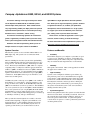
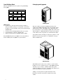
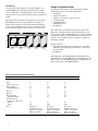
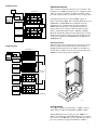
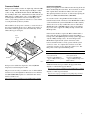
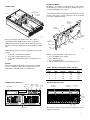
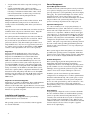
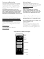
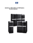
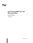
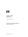
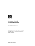
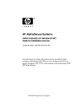
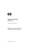
AlphaServer GS80, GS160, and GS320 Systems
Technical Summary
Contents
System Overview 1
Hardware and Software Partitioning 12
Features and Benefits 1
Storage 12
Fibre Channel 12
RAID 12
Quad Building Block 2
QBB Features 2
Packaging and Upgrades 2
System Configurations 3
Color Coding 3
Site Planning 4
Comparison of System Features 4
Design and Implementation 4
Switch Interconnect 5
Hierarchical Switch 5
Switch Bandwidth 5
System Control 6
System Control Features 6
Console Serial Bus Block Diagram 6
Power 7
AC/DC and Vaux 7
Power Supply Features 7
PCI Power Supply 7
Modularity of Power System 7
Power Modules in the QBB 7
Benefits of Power System 7
Third-Generation Alpha Chip 8
Chip Operation 8
Alpha 21264 Features 8
Processor Module 9
Performance Upgrades 9
Memory 10
Performance Considerations 10
Upgrades 10
System I/O 10
All PCI Boxes 10
PCI Master Box 11
Standard I/O Module 11
Features 11
PCI Master Box, Front and Rear Views 11
Clustering 12
Compaq Tru64 UNIX 13
OpenVMS 13
Reliability, Availability, and Maintainability 13
System Features 13
High Availability 13
Parity and Error Correction 14
Diagnostics 14
Diagnostics and Firmware Upgrades 14
Installation and Upgrades 14
Server Management 14
System Management Console 14
Operational Management 14
Platform Management 14
Error Reporting 14
Performance and Benchmarking 15
Sources of Performance Information 15
Information for Compaq Partners 15
Service and Support 15
Hardware Warranty 15
Software Warranty 15
Compaq AlphaServer GS80 System Diagram 15
Compaq AlphaServer GS160/320 System Diagram 16
System Features at a Glance 17
Physical Characteristics and Operating Environment 18
Compaq AlphaServer GS80, GS160, and GS320 Systems
The newest offerings in the high-end enterprise market
OpenVMS on a single AlphaServer GS series platform.
are the AlphaServer GS80, GS160, and GS320 systems
This allows you to stage new operating systems, database
with the Alpha 21264 processors. When combined with
or application releases; or, combine your production,
very large memory (VLM64), the Alpha processors provide
development, and test environments in a single system;
unprecedented response times in transaction processing,
or, support your server consolidation plans and strate-
database access, simulations, and file serving.
gies, adding value to your hardware investment.
The two-level switch design provides for incremental
growth, supported by a modular power system that is key
to the system management control and redundant features.
Hardware and software partitioning allows you to run
These servers are ideal for applications such as gene
research, weather tracking, and industrial design.
For more information on these AlphaServer systems, see
http://www.compaq.com/alphaserver/servers.html
multiple instances or copies of either Tru64 UNIX or
System Overview
Features and Benefits
The GS series systems are now available with the 1001 or 731
MHz Alpha chip. The systems even accommodate mixedspeed CPUs.
•
The basic building block of these systems is the quad building
block or QBB, which provides the switch interconnect for up to
four processors, four memory modules, and the I/O port to PCI
boxes. The memory bandwidth for a QBB, which is a complete
computing entity, is 7 Gbytes/second. The aggregate I/O bandwidth for a QBB is 1.6 Gbytes/second. Two QBBs communicate
through their global ports. A system with more than two QBBs
requires a hierarchical switch, which allows up to eight QBBs to
communicate. Each QBB can have up to two PCI boxes, each
with 14 slots for PCI options.
A GS80 rack system can have up to two QBBs, each of which is
the backplane of a system drawer. All power, PCI boxes, and
storage are in the same cabinet. In the GS160/320 systems, the
QBBs are mounted back to back in a system box. The GS160 has
one or two system boxes (two or four QBBs), and the GS320 has
three or four system boxes (six or eight QBBs). Both the GS160
and GS320 have a separate cabinet used for power, storage, and
PCI boxes. A fully configured GS320 supports up to 32 CPUs, up
to 256 Gbytes of memory, and up to 224 PCI slots.
These systems have been designed to be scalable, to be maintainable without requiring a complete system shutdown, to be
managed remotely, to offer reliability with support for many
redundant features, and to offer flexibility in your choice of
operating system and how you use the hardware resources.
Scalability
The modular design lets you configure a system that can grow
to 32 processors, 256 Gbytes of memory, and 224 PCI slots,
without investing in the cabinets and power components until
they are needed. Growth and performance are incremental.
•
Flexibility
CPU speeds can be mixed. CPUs can be upgraded even while
the applications continue to run.
•
High Availability
Systems can be configured to eliminate power failures, by
using alternate power sources and redundant, hot-swappable
power supplies. Other redundant features ensure that system
resources are available when needed: the console subsystem,
I/O subsystems, networks, and storage devices. Hard partitioning of the system, and the ability to power down parts of
the system, means that the system can be serviced without
shutting down the entire system.
•
System Management
Remote management features allow systems to be installed and
run from locations where accessibility is restricted. Sensors in
the system monitor environmental conditions, and alerts are
sent to the operator when needed. A system management
console allows an operator to control a partitioned system from
one management station.
1
Packaging and Upgrades
Quad Building Block
The basic building block of all systems is the quad building
block (QBB).
CPU
I/O
MEM
CPU
CPU
Switch
MEM
MEM
CPU
GP
MEM
MRO346
PK2237
GS80 System
QBB Features
•
•
•
•
Connectors for four CPU and four memory modules, a
directory module, global port, clock splitter, two I/O riser
modules, two power modules, and a power system manager
(PSM) module
Can be powered off independently from rest of system.
Can be defined as a discrete computing unit.
20-layer circuit board, 18 x 20 inches with 13 ASICs
In the GS160/320 systems two QBBs are in each system box,
and in a GS80 system one QBB is in a system drawer.
The same cabinet is used for the GS80 system, the power
cabinet in the GS160 and GS320 systems, the expander cabinet,
and the transfer switch. The GS80 system cabinet holds up to
two system drawers, each containing a QBB. The system comes
with one PCI box. Additional PCI boxes and/or storage shelves
can be added. Power components are contained in the cabinet.
An expander cabinet can hold up to eight storage shelves or four
PCI boxes and one storage shelf, or a combination of storage
shelves and PCI boxes.
System Cabinet 1
Power Cabinet
PK2236
GS160 System
The GS160 system consists of two cabinets: a system cabinet
holding one or two system boxes (two or four QBBs) populated
with the processor, memory, and I/O modules and a power
cabinet. In addition to the power components, this cabinet is also
used to house PCI boxes and storage shelves.
Adding a second system box requires installation of the
hierarchical switch located at the rear right of the system
cabinet.
2
The GS320 system requires another system cabinet to hold
additional system boxes. The second system cabinet can be a
field upgrade. If the hierarchical switch is not present in system
cabinet 1, it must be installed as part of the upgrade. The
GS320 system has three or four system boxes (six or eight
QBBs).
System Configurations
A GS160 system can have up to two system boxes, each of
which has two quad building blocks. The QBBs are mounted
back to back. Each system box requires its own power subrack
which is located in the power cabinet.
To accommodate more system boxes, you simply add another
system cabinet. Another system cabinet, holding one or two
system boxes, makes this a GS320 system. The GS160 is
identified as a Model 4 or 8; a GS320 system as a Model 8, 16,
24, or 32. The model number indicates the maximum number of
processors possible in the system.
Each system has a master PCI box, which in addition to
containing several I/O devices and PCI option slots, holds the
standard I/O module. This module is a key component of the
system. It controls the I/O subsystems and also monitors and
controls the state of the entire system. Because of its importance
in these two areas, users may want to configure a second master
PCI box into their systems. It can function as a standby console
and/or as a redundant control system. It is advised that any
system with a second console use the optional terminal server.
System Cabinet 2
System Cabinet 1
Power Cabinet
PK1522
Color Coding
Components of the system are color coded to assist service
personnel. Each system box has a different color code, and the
components that are associated with that box are all identified
by that same color code: the power subrack, the AC input box
outlets and circuit breakers, and cables. The slots in the system
box and the different types of modules (CPU, memory, power,
etc.) are also color coded so that modules can be installed in the
correct slots.
GS320 System
For details on processor upgrades, see p. 9.
System
Box 2
System
Box 4
System
Box 2
System
Box 1
System
Box 3
System
Box 1
PK0614
GS160 System
PK0615
GS320 System
3
Site Planning
Design and Implementation
An entry-level system, whether a one-cabinet GS80 or a twocabinet GS160 can be upgraded to meet future needs. Therefore, it is important to consider both space and power requirements not only for today but for the time when you expand your
system.
We asked customers what was important to them and then
designed this system to meet these requirements.
• Scalability
• Lights out operation
• Ability to consolidate or isolate resources
• Avoid downtime
• Distributed memory
• Distributed power
• Redundancy
The diagram below shows the space required for each cabinet.
The GS80 is the same size as the cabinets on the right. If a
transfer switch cabinet is to be installed, it must be beside the
power cabinet. Expander cabinets can go on either side of the
power or system cabinets, or they can be up to 7 meters away.
200 cm
(78.7 in)
60 cm
(23.6 in)
The architecture was optimized for large-scale applications,
taking into account the tradeoffs required allowing it to scale
versus the cost. With a fixed number of slots you have tradeoffs
between CPU, memory, and I/O. With these systems there is no
tradeoff. You can add more memory and I/O as you increase
the number of CPUs.
60 cm
(23.6 in)
100 cm
(39.4 in)
System
Cabinet 2
System
Cabinet 1
Power
Cabinet
Dual-AC
Cabinet
Design constraints:
• The CPUs and memory had to be kept in close proximity.
This meant segregating the power delivery system away
from the CPUs.
• Redundancy
Expander
Cabinet
PK2246
The architecture of the GS80, GS160, and GS320 systems is
essentially the same. The QBB is the basic building block. The
CPUs, memory, and the I/O and global ports communicate by
means of the switch on the QBB backplane.
Table 1 Comparison of System Features*
Feature
GS80
GS160
GS320
QBBs
2
4
8
CPUs
8
16
32
Partitions supported
2
4
8
Memory (GB)
Bandwidth (GB/sec)
64
14
128
28.5
256
57
PCI boxes
4
8
16
PCI buses
16
32
64
PCI slots (64 bit)
Bandwidth (GB/sec)
56
3.2
112
6.4
224
12.8
Internal disk storage
(system/power cabinet only)
Spindles
Gbytes
14
504
28
1008
28
1008
Single phase
Redundant DC power
supplies and redundant
PCI power supplies
Three phase
Redundant DC power
supplies and redundant
PCI power supplies
Dual AC power switch
Three phase
Redundant DC power
supplies and redundant
PCI power supplies
Dual AC power switch
Power
* Maximum configuration.
4
One-Box System
Switch Interconnect
Modem
These systems are designed around two levels of switches. The
backplane of each QBB contains the logic for a multiport switch
with ports for up to four CPUs, four memory modules, an I/O
port, and a global port that can send and receive on separate lines.
System Box
PCI Box
CPU
Standard
I/O SCM
I/O
MEM
Operator
Console
CPU
CPU
Switch
MEM
MEM
CPU
GP
MEM
PCI Box
Distribution
Board
CPU
PCI Box
I/O
MEM
CPU
CPU
Switch
MEM
PCI Box
MEM
CPU
GP
MEM
PK-0601-98
Communication between two adjacent QBBs requires an
interface between the QBBs; this is called the distribution board.
GS80 Model 8 and GS160 Model 8 configurations use the
distribution board. Communication among more than two
QBBs requires another type of switch (shown in the block
diagram of the two-box system). This is the global switch or
what is called the hierarchical switch. AlphaServer GS160
Model 16 and GS320 configurations use the hierarchical switch.
The hierarchical switch is in the system upgrade kit that is used
to upgrade an AlphaServer GS160 Model 8 to an AlphaServer
GS160 Model 16.
Hierarchical Switch
The hierarchical switch is mounted at the rear right of a cabinet
with two system boxes (the hierarchical switch assembly is
highlighted in the figure below). In addition to the ASICs for
the switch, the assembly also has its own power microprocessor
(HPM) and contains the system clock module.
Two-Box System
System Box 1
Modem
PCI Box
Standard
I/O SCM
CPU CPU CPU CPU
I/O
Switch
GP
MEM MEM MEM MEM
Operator
Console
PCI Box
CPU CPU CPU CPU
PCI Box
I/O
Switch
GP
MEM MEM MEM MEM
PCI Box
System Box 2
Hierarchical
Switch
CPU CPU CPU CPU
PCI Box
I/O
Switch
GP
MEM MEM MEM MEM
PCI Box
CPU CPU CPU CPU
PCI Box
I/O
Switch
GP
MEM MEM MEM MEM
PCI Box
PK-0623-98
REAR
PK1282
Switch Bandwidth
On a QBB each CPU is guaranteed up to 1.7 GB/sec of bandwidth. With four CPUs the bandwidth per QBB is 7 GB/sec.
The bandwidth between two global ports (two QBBs) is 1.7
GB/sec. in each direction. The bandwidth increases by a multiple of four for each QBB added, so that a GS320 system with 32
processors provides an aggregate bandwidth of 57 GB/sec.
5
System Control Features
System Control
•
The console serial bus (CSB) consists of a number of
microprocessors distributed throughout the system. Their
function is to monitor and control the system, including the
operator control panel (OCP).
•
•
•
The OCP provides a power-on keyswitch, Halt, Fault, and Reset
buttons, a four-line by 20 character display, with three LEDs
(Secure, Power OK, and Halt). The operations performed at the
control panel can also be performed from a serial console at a
local terminal or from a remote site.
•
Vaux power generated by the 48V power supplies powers
the console serial bus.
Optional standby console serial bus
Remote management interface
Option of setting up eight partitions in one system and
running different operating systems in each.
Capability of hot swapping components or adding
components to a running system.
It is the system control manager (SCM), a microprocessor on the
console serial bus that controls the system. The SCM can tell the
PSM to power up the QBB that it controls; it then tells the PBMs
to power up the PCI boxes, and the HPM to power up the Hswitch.
Console Serial Bus Block Diagram
QBB4
QBB0
GP
PSM
Hierarchical
Switch
GP
QBB5
QBB1
GP
PSM
GP
GP
GP
CSB Microprocessors:
SCM - System Control Manager
PSM - Power System Manager
PBM - PCI Backplane Manager
HPM - Hierarchical Switch Power
Manager
PSM
QBB7
QBB3
PSM
PSM
QBB6
QBB2
PSM
PSM
GP
GP
PSM
HPM
PCI1
PCI0
PBM
PCI2
PBM
SIO
PCI3
PBM
SIO
SCM
Console
6
PBM
SCM
OCP
Standby
Console
MR0341
Power
Some customers who require a system that has the size and
complexity of a fully configured GS320 want that system to
remain powered at all times. The electrical infrastructure of
their facilities must be able to provide a sure and steady supply
of power under all circumstances. To meet that need, an
optional dual AC power switch can be used to allow power to be
fed from two different sources: either another utility source or
from an uninterruptible power source (UPS).
The need for calculating power required should not be
underestimated. Consult Tables 5, 6, and 7.
AC/DC and Vaux
An auxiliary power system, known as Vaux, allows control of
the system even when DC power is not being supplied to the
QBB. Vaux powers the console serial bus, which connects the
microprocessors distributed throughout the system.
The GS160 and GS320 systems are three phase. The GS80
system and the expander cabinets are single-phase power. The
power supplies used with the system boxes and drawers are
1600 watts and 1000 watts, respectively.
Each system box and drawer requires two 48V power supplies,
and a third can be added to provide redundancy.
Power Supply Features
• Hot swappable
• Dual-speed internal fan
• Remote sense
• Remote enable
• Fault protection: overcurrent, overvoltage, overtemperature
• Status LEDs: Vaux, 48V
Converters throughout the system convert the 48 volts to the
voltage required by the various modules.
PCI Power Supply
Each PCI box has two power supplies; the second is for
redundancy, and it is hot swappable.
Modularity of Power System
Power Modules in the QBB
Each QBB has a power system manager module (PSM) that
controls the power-up and power-down of that QBB. It
responds to commands from the SCM on the console serial bus.
If the PSM detects a fault or a change in environmental
conditions, such as a rise in temperature or voltage, it will take
appropriate actions. For example, the PSM increases the speed
of the blower if more air circulation is required.
The PSM has a manual setting to turn off power to the QBB as a
safety feature for anyone servicing this area of the machine.
Each QBB also has two power modules: one called the main
power module and the other called the auxiliary power module.
Both convert the 48 VDC to the regulated DC voltages required
by the logic module.
Following are the voltages provided:
Main
Auxiliary
+3.3
+3.3
+3.3VP (PLL power)
+2.5
+1.7
–1.7 (PLL power)
+2.5
PLL (phase lock loop) power keeps clocks synchronized.
Both modules provide:
• Remote On/Off control
• Remote sense
• Fault protection and isolation
• Status indicators and signals for fault isolation
2
• I C interface
Benefits of Power System
Power supplies and converters are distributed throughout the
system. And because of the modular nature of the system, you
can add power as you add capacity. As more capacity is needed,
you then add the required power needed to support the added
capacity. Because each processor module has its own power
converter, any new processor modules with different voltage
requirements can be added without any changes to the power
system.
Each system box has its own 48V power supplies, which are
located in a power subrack of the power cabinet. For ease of
servicing, all components associated with that system box
(power supplies, power plugs and circuit breakers on AC input
boxes, and cables) are labeled with the same color coding.
7
Third-Generation Alpha Chip
The third generation of the Alpha microprocessor, the Alpha
21264, is a superscalar superpipelined implementation of the
Alpha architecture. The first offering of this chip was known as
EV6. These systems are offered with the EV67 chip (.28 micron)
and the EV68 chip (.18 micron). Over 15.2 million transistors
are on one die. In our discussion here, the Alpha 21264
designation applies to all variants of the chip.
Designed for performance, the Alpha 21264 achieves this goal
by carefully studied and simulated architectural and circuit
analysis. The 21264 memory system also enables high performance levels. On-chip and off-chip caches provide for very
low latency data access, which allows for very high bandwidth
data access. (With the Alpha EV67 chip the size of the off-chip
cache is 4 MB running at 366 MHz; with the EV68 chip the
size of the off-chip cache is 8 MB running at either 626 or 667
MHz, depending on the system clock speed.)
Internal to each chip is a 64-Kbyte instruction cache (I-cache)
and a 64-Kbyte data cache (D-cache).
• I-cache. 64 Kbytes, two-way set-associative, virtually
addressed cache with 64-byte blocks
• D-cache. 64 Kbytes, two-way set-associative, virtually
indexed, physically tagged, writeback cache with 64-byte
blocks
Chip Operation
Several key design choices were made in the chip architecture
to maximize performance: Four instructions are fetched each
cycle, and then how those instructions are handled boosts the
speed of execution. Register renaming assigns a unique storage
location with each write reference to a register, avoiding register
dependencies that can be a potential bottleneck to processor
performance.
Another design feature, out-of-order execution, permits
instructions to execute in an order different from the order that
the instructions are fetched. In effect, instructions execute as
soon as possible. This allows for faster execution since critical
path computations are started and completed as soon as possible.
In addition, the Alpha 21264 employs speculative execution to
maximize performance. It speculatively fetches and executes
instructions even though it may not know immediately whether
the instruction will be on the final execution path. This is
particularly useful, for instance, when the 21264 predicts branch
directions and speculatively executes down the predicted path.
The sophisticated branch prediction in the 21264 coupled with
the speculative and dynamic execution extracts the most
instruction parallelism from applications.
For more information about the chip, see:
http://www.compaq.com/alphaserver/download/ev6chip.pdf
8
Alpha 21264 Features
•
•
•
•
•
•
•
•
•
•
•
Out-of-order instruction execution
Large (64 Kbyte) on-chip data and instruction caches
Improved branch prediction through intuitive execution
Register renaming
Increased bandwidth for high-speed access to second-level
cache and system memory
Motion video instructions
Square root and divide instructions
All instructions are 32 bits long and have a regular
instruction format
Floating-point unit, supports DIGITAL and IEEE floatingpoint data types
80 integer registers, 64 bits wide
72 floating-point registers, 64 bits wide
Performance Upgrades
Processor Module
Each processor module contains one Alpha chip, either the 1001
MHz or 731 MHz chip. The CPU chip has 64-Kbyte I- and Dcaches on-chip. The B4166 module with the 1001 MHz chip
has an 8-Mbyte ECC cache, and the B4125 module with the 731
MHz chip has a 4-Mbyte ECC cache. On the QBB backplane
are DTag chips that track the status and ownership of each
CPU’s cache, making possible fast references to cache without
accessing the memory directory module.
The module has its own power converter, to convert 48 volts to
the voltages needed by the processor. With a power supply on
the module, module upgrades can be done efficiently, as new
CPU technology is developed.
Power
Converter
In the past an upgrade to faster CPUs meant removing all the old
CPUs and installing the faster CPUs. Now customers can retain
their original CPUs and add faster CPUs to the same system.
The optimal performance, however, is achieved by replacing the
B4125 (731 MHz) with B4166 CPUs (1001 MHz).
If a customer wants to keep the B4125 CPU modules, some
tradeoffs must be made. The newer, faster B4166 CPU modules
can be installed in the system with the B4125 modules, but they
will not run as fast as they would if there were no older CPUs
(B4166 CPUs run at 940 MHz with the 9.6 ns clock) and they
may not be able to support the 8-Mbyte backup cache that the
B4166 provides.
If the customer decides to replace the B4125 CPU modules, a
new system box may be required that supports the 8-Mbyte
backup cache. (The QBB backplanes in early systems supported
only the 4-Mbyte backup cache.) To run at full speed, the
B4166 CPUs require that the system clock run at 9.0 ns;
however, the B4125 CPUs can only operate with the system
clock set to 9.6 ns. To complete the conversion of an older
system, the customer can also change the cabinet color. The
blue panels can be replaced with black panels.
CPU
Chip
Early Systems
731 MHz CPU (B4125 module)
9.6 ns system clock
System box with QBBs that
support 4-Mbyte backup cache
Blue cabinets
Run LED
Hot Swap
LED
Today’s Systems
1001 MHz CPU (B4166 module)
9.0 ns system clock
System box with QBBs that
support 8-Mbyte backup cache
Black cabinets
PK0602
Each processor module has diagnostics on-board (SROM
diagnostics) used in testing the module.
The processors are easily accessible for ease of online addition
and removal. See the AlphaServer Web site for more information (EK-GSHPG-RM, AlphaServer GS160/320 CPU Online
Addition and Removal):
http://www.compaq.com/alphaserver/gs160/gs160_tech.html
Additional information is provided in the upgrade manuals:
AlphaServer GS160/320 Upgrade Manual
http://www.compaq.com/alphaserver/gs160/gs160_tech.html
AlphaServer GS80 Upgrade Manual
http://www.compaq.com/alphaserver/gs80/gs80_tech.html
9
Memory
The fact that memory is distributed throughout the system
impacts several functions of the system:
• Memory latency
• Cache coherency
• Partitions
• Configuration of memory depending upon the application
needs
Each QBB supports up to four memory modules and can keep
track of all memory transactions for that QBB. When a second
QBB is populated, a record must be kept of what has been
cached. A memory directory module is then required in each
QBB, and it functions as a memory coherency manager. Each
DIMM on a directory module is associated with a memory array
on that QBB backplane. Whenever an array is added to a
memory module, a DIMM must be added to the directory
module.
For fast retrieval of cached data, DTags are on the QBB
backplane near each memory module slot.
Each memory module supports eight DIMMs, which are split
between two arrays. A memory option consists of a base module
with one memory array. A second array can be added.
DIMMs
With four fully populated memory modules in a QBB, the
aggregate bandwidth is 7 Gbytes/second. To achieve the
maximum interleave (32-way interleave), all memory arrays
must have the same size DIMMs.
Upgrades
Memory can be upgraded in several ways.
1. Add a second array (four like DIMMs) to the base module;
the second array need not be the same size DIMMs as the
first array.
2. Add more memory modules.
3. Change the size of the DIMMs on the memory modules.
System I/O
Communication with the I/O subsystem is through the I/O riser
modules in the QBB. Each QBB can have up to two I/O riser
modules. Each I/O riser in the QBB connects to one 14-slot PCI
box, and therefore each QBB can support up to two PCI boxes.
A system box with two QBBs can support up to four PCI boxes.
In the PCI box there are also I/O riser modules. The QBB I/O
riser modules are called “local” I/O riser modules, and those in
the PCI boxes are called “remote” I/O riser modules. Each local
I/O riser module on the QBB has two cables connecting the
QBB and PCI box. Each cable connects to two PCI buses in the
PCI box, one three-slot bus and one four-slot bus.
Remote I/O
Riser Modules
PCI Box
Local I/O
Riser Modules
Remote I/O
Riser Modules
PCI Box
MR0345
PK0603
Memory options are available in the following array sizes:
512 Mbytes and 1, 2, and 4 Gbytes.
A GS80 system supports up to 64 Gbytes of memory, a GS160
system supports up to 128 Gbytes, and a GS320 up to 256
Gbytes.
All PCI Boxes
PCI boxes have four PCI bus segments: two with four slots, and
two with three slots. All PCI slots are 64-bit, 33 MHz and are
compatible with Rev. 2.2 of the PCI specification; 32-bit PCI
options are also supported.
Every PCI box must have a unique node ID from 0 to 15, which
is set using a switch on the PCI box. This setting determines the
CSB node addresses for the SCM and PBM.
Performance Considerations
When configuring a system, one must consider the number of
hardware partitions and requirements of the application. Each
memory module is capable of 4-way interleaving with one
array, or 8-way interleaving with two arrays. Interleaved
operations reduce the average latency and increase the memory
throughput over noninterleaved operations.
10
The PCI backplane has a microprocessor, the PBM, that reports
back to the SCM about the status of the PCI box. There is also a
jumper on the backplane that can be installed that will force the
PBM into fail-safe loader mode.
Standard I/O Module
In addition to the connectors for the I/O devices, each standard
I/O module has a system control manager (SCM) microprocessor and flash EROMs for the console.
PCI Master Box
DVD/CD
Remote
I/O Riser Modules
A standard I/O module is required for each partition in a system,
because each requires a console connection to the local terminal
port on the standard I/O module.
Hard Disk
Standard
I/O Module
STD I/O
Cable Interface
Connector
Unused
Fast-Wide
SCSI Connector
SCM Flash
EPROM
SCM
EEPROM
MR0343
Each system requires one PCI master box that contains a
standard I/O module, DVD/CD drive, and a system disk.
Additional PCI expansion boxes hold only PCI option boards
and do not contain the standard I/O module, DVD/CD, and disk
drive.
Additional PCI master boxes may be required for the following
reasons:
• To provide a redundant I/O subsystem.
• To provide a standby SCM and console.
• To provide a standard I/O module for each partition in a
system.
Features
The maximum I/O bandwidth for one system box (four PCI
boxes) is 3.2 Gbytes/second. The maximum aggregate I/O
bandwidth for a GS320 system is 12.8 Gbytes/sec.
PCI Master Box, Front View
DVD/CD-ROM
DVD/CD
Connector
Local
Terminal Port
SRM Console
Flash EPROM
SRM
EEPROM
USB Ports
Modem
Port
Jumpers
PK1278
Jumpers on the standard I/O module can be set to:
• Force the SRM console defaults
• Force COM1 bypass
• Force the SCM defaults
• Put the SCM into fail-safe loader mode upon reset
Table 2 Numbers of PCI Boxes, Buses, and Slots
System
Boxes
QBBs
PCI Boxes
PCI Buses
Slots
1
2
3
4
2
4
6
8
4
8
12
16
16
32
48
64
56
112
168
224
PCI Master Box, Rear View
Keyboard COM 2
Serial Port
Mouse
Operator
Control
Panel
Parallel
Port
Remote I/O
Riser Module
Remote I/O
Riser Module
Local Terminal
Port
LEDs
CSB Node
ID Switch
CSB
USB
Ports
Power Supplies
PK1279
Modem
Port
PK1277
The USB ports shown on the rear of the master PCI box are not
supported at this time.
11
Two storage shelves can be added to the power cabinet of
GS160/320 systems. One storage shelf can be added to the
These systems support partitioning, which allows you to run multiple
GS80 system cabinet. Expander cabinets that can be up to 7
instances of either the Tru64 UNIX or OpenVMS operating systems
meters away from the system can also be used for additional
on one hardware platform. This feature can help you consolidate
storage; up to eight StorageWorks shelves can be installed in an
several different computing resources into one hardware system,
expander cabinet.
thereby reducing floor space requirements, power consumption, and
heat dissipation—or it can allow you to reallocate your resources to
External storage arrays such as the ESA 10000 and 12000 and
separate environments. The GS320 system can have up to eight hard
SW800 CI storage arrays can be configured to support RAID.
partitions—one for each QBB; the GS160
can have up to four hard partitions. The GS80 can have two hard
Fibre Channel
partitions.
Available on these AlphaServer systems is the next storage
interface, Fibre Channel, which eliminates issues with today’s
The SCM is used to set up hard partitions, and the SRM console is
SCSI interfaces such as distance, bandwidth, scalability, and
used to set up soft partitions. With multiple partitions and master
reliability. Fibre Channel (FC) is the answer to not only serverPCI boxes there is one master SCM of the CSB. The master is
to-storage connections but also to server-to-server networking,
determined by the setting of the PCI box ID switch, from 0 to 15.
because multiple protocols are supported. SCSI, TCP/IP, video,
The master will be the SCM in the PCI box set to the lowest
or raw data can all take advantage of high-performance, reliable
number, 0, that is also connected to the control panel.
Fibre Channel technology.
Hardware and Software Partitioning
Each instance of an operating system requires its own console,
so each partition, hard or soft, must have a separate console
connection. This connection from the local terminal port on the
standard I/O module can be made to a stand-alone console
device or to a terminal server controlled by the system
management console, a PC.
Each hard partition must have a minimum of one processor
module, one memory module, one I/O port module, and one
master PCI box.
With OpenVMS you can have both hard partitions and soft
paritions. Soft partitioning allows some system resources to be
shared. For example, memory and CPUs can be dynamically
reallocated as applications running on different partitions change
their requirements. An AlphaServer GS system with multiple
hardware partitions could have one of those partitions configured to
run multiple instances of OpenVMS.
The Tru64 UNIX operating system supports only hard partitions.
With the KGPSA PCI Fibre Channel adapter, the GS80/160/320
systems provide a storage interconnect that is 2.5 times as fast
as UltraSCSI: 100 vs 40 Mbytes/sec data throughput. The
KGPSA adapter allows you to manage storage including the
HSG80 RAID controller in a switched FC topology.
RAID (Redundant Array of Independent Disks)
With optional PCI RAID controllers you can organize disk data
cost-effectively, improve performance, and provide high levels
of storage integrity (not yet supported).
The optional RAID controllers have the following features:
• Support for hot-swap drives
• Automatic rebuild after hot swap
• Console support for booting system from RAID
• RAID levels 0, 1, 0+1, 3, 5
• Optional write cache
• Optional read cache
• Support for command queuing
Storage
Clustering
Large numbers of storage devices can be configured into these
systems. Ultra3 and UltraSCSI StorageWorks shelves are
supported. Ultra3 shelves hold 14 one inch disks, while the
UltraSCSI shelves hold seven 3.5” disks. With Ultra3 and 36.4Gbyte disks you can have over 500 Gbytes in one shelf; with
UltraSCSI and 36.4-Gbyte disks you can have over 250 Gbytes.
A cluster is a loosely coupled set of systems that behaves (is
addressed and managed) like a single system, but provides high
levels of availability through redundant CPUs, storage, and data
paths. Clusters are also highly scalable, meaning that CPU, I/O,
storage, and application resources can be added incrementally to
efficiently grow capacity. For customers, this translates to
reliable access to system resources and data, and investment
protection of both hardware and software.
Each UltraSCSI shelf can hold a maximum of seven 3.5” devices
or two 5.25” devices and one 3.5” device. The StorageWorks
shelves are 16-bit (wide) UltraSCSI. (FAST-10 SCSI configurations require that a DWZZA or DWZZB bus adapter be installed in
each shelf, taking the place of one disk). The UltraSCSI building
blocks include embedded DWZZC, thus allowing a full complement of up to seven UltraSCSI drives per shelf.
12
Clustering allows multiple computer systems to communicate
over a common interface, share disks, and spread the computing
load across multiple CPUs.
The primary means of clustering systems depends on the
operating system.
• CI clusters, OpenVMS only
• Memory Channel, Compaq Tru64 UNIX and OpenVMS
• SCSI clusters, Compaq Tru64 UNIX and OpenVMS
• FDDI clusters, OpenVMS only
System Features
Under Compaq Tru64 UNIX and OpenVMS, you can build highavailability clusters using the Memory Channel interconnect.
The Memory Channel interconnect is a high-bandwidth, lowlatency PCI-based communications interconnect for up to eight
AlphaServer systems. Data written to one computer’s memory
is shared by other computers on the Memory Channel bus.
•
The PCI CCMAB adapter is the interface between a PCI and a
Memory Channel bus. This bus is a memory-to-memory
computer system interconnect that permits I/O space writes in
one computing node to be replicated into the memories of all
other nodes on the Memory Channel bus. A write performed by
any CPU to its reflected address region will result in automatic
hardware updates to memory regions in other nodes. One
node’s write is “reflected” to other nodes as a direct side effect
of the local write. This provides a memory region with
properties similar to a high-performance shared memory across
a group of nodes.
High Availability
Compaq Tru64 UNIX
For clustered Compaq Tru64 UNIX systems, TruCluster
Software solutions allow users access to network services and
provide further failover recovery from server, network, or I/O
failures. Compaq Tru64 UNIX cluster systems use the SCSI or
Fibre Channel interconnects between disks and systems, and
Memory Channel, Fast/Gigabit Ethernet or Quadrix ELAN
interconnects, between systems themselves.
OpenVMS
Under OpenVMS, you can build CI, SCSI, FDDI, Memory
Channel, and Ethernet-based clusters (for this class of system,
we do not recommend Ethernet-based clusters) using the
following hardware:
• CI clusters using the CIPCA
The HSJ controller connects to the CI cluster and provides
for SCSI storage.
• SCSI clusters using the KZPBA (UltraSCSI)
• SCSI clusters using the KGPSA (Fibre Channel)
• FDDI clusters using the DEFPA PCI option
• Memory Channel clusters using the CCMAB PCI adapter
Reliability, Availability, and
Maintainability
The AlphaServer GS80/160/320 systems have numerous
features that improve their reliability and availability. The
overall system reliability benefits from extensive use of CMOS
technology in the design. The improvements are gained by
having high circuit density, less interconnect and overall less
heat dissipation than other technologies. Availability is
improved by having more error detection and retry of error
conditions.
•
•
•
•
•
•
•
•
Separate management bus (CSB)
Built-in self-test and console ROM-based diagnostics at
system level
Console messages reflecting the status of booting
Parity and error correction (ECC) on the QBBs, all
secondary caches, and memory
Test-directed diagnostics and symptom-directed
diagnostics
System fault management
Ease of repair
Online system exercisers
Redundant, hot-swappable power supplies
The following features address high availability:
• Optional redundant console to manage the entire system.
• Partitioning allows you to physically isolate portions of the
system. Each partition has its own resources and runs its
own copy of an operating system. The operating system
need not be the same version or even the same operating
system as that running in other partitions. Because power
can be removed from an individual QBB, you can service
parts of the system without shutting down the entire
system.
• Online addition and removal of processor modules.
• Clustering provides continuous availability, to storage and
to computational abilities and applications, in spite of
failure of a complete system.
• With the Compaq Tru64 UNIX operating system,
TruCluster Server software provides for application
failover. By monitoring the performance of cluster
members and automatically initiating recovery procedures
in the event of system or component failures, a TruCluster
system ensures system availability.
• RAID (redundant array of independent disks) may be
deployed to enhance availability of storage. We offer
RAID level 0 which improves performance by spreading
I/O over a number of disks, RAID level 1 (a 1:1 highperformance redundancy technique), and RAID levels 3
and 5 (an N+1 redundancy technique) in a variety of
implementations: layered product software, internal
controllers on the PCI I/O bus (not yet supported), and
external controllers for clusters.
• Disks may be hot swapped to eliminate a source of system
downtime. When used with RAID configurations, hot
swapping is transparent to applications and to users.
External RAID controllers may be configured to
automatically replace failed disks in RAID sets with hot
spare units.
• Thermal management. A large custom blower in the
system cabinet controlled by the PSM speeds up to
compensate for a rise in temperature. In addition, each PCI
box has two fans.
• N+1 redundant power supplies keep a system running even
if a power supply fails. The 48V power supplies are hot
swappable. The PCI boxes and the hierarchical switch also
have redundant power supplies that are hot swappable.
13
•
•
An optional dual AC switch can provide a backup power
source.
Systems with multiple CPU or memory modules
automatically recover from failures of those modules, by
rebooting to exclude those failed modules. Thus, a hard
fault is transformed into a transient outage, followed by
continued operation with degraded performance.
Parity and Error Correction
Multiple ECC checks provide for better failure isolation. Each
checkpoint within the system preserves error information,
assisting software in determining where in the system the error
originated.
Parity protection is used on the address bus, and on the data bus an
8-bit ECC check code protects each 64 bits of data. Single-bit
errors are corrected, and double-bit errors are detected.
For optimal performance and integrity, the memory modules do
not correct the data when single-bit errors are detected. When
they are detected, the system firmware will scrub them to
prevent reoccurrence. Only CPU and I/O port modules correct
single-bit ECC errors. Any errors are logged in the system error
log, and the console program can then identify a failing DIMM,
so that it can be replaced if the same error occurs repeatedly.
Diagnostics
In keeping with the distributed nature of the system, the
diagnostics too are distributed. Each processor module has
diagnostics in an SROM used to test that module. These
diagnostics are the first to execute at power-up. Then each
PSM loads additional extended SROM diagnostics into each
processor to test the rest of the system. These diagnostics are
stored in flash ROM so that they can be updated. This testing
goes off the module to test the quad switch. All QBBs do their
testing concurrently. As the SCM sees the CPUs in the system,
it then elects a primary CPU to complete the initialization of the
hierarchical switch. The primary CPU then sees all other QBBs
besides its own and conducts tests using the H-switch. Upon the
successful completion of the tests, control then passes to the
SRM console.
Diagnostics and Firmware Upgrades
Diagnostics are available on a DVD/CD. The Loadable Firmware
Update Utility (LFU) can be used to check the revision of
firmware on all modules and to upgrade firmware as new revisions
are required. Or, the SCM update command can be used to update
firmware on a specified component.
Installation and Upgrades
System installations and upgrades must be performed by
qualified customer service technicians.
The operating systems are factory installed; software upgrades
are customer installable.
14
Server Management
System Management Console
A workstation-based system management console provides the
access point for managing system console functions such as
power-up, diagnostics, system partitioning, and console display
and logging. For systems with multiple console lines, such as
partitioned systems or those with a backup console line, a
terminal server is used to concentrate the multiple console lines
and present them to the system management console so the
operator can manage all partitions from a single point.
Operational Management
Server/Network Management. Compaq Insight Manager is
included with every system. This software tool allows you to
monitor and control Alpha-based servers. Insight Manager
consists of two components: a Windows-based console application and server- or client-based management data collection
agents. Management agents monitor over 1,000 management
parameters. Key subsystems are instrumented to make health,
configuration, and performance data available to the agent
software. The agents act upon that data, by initiating alarms in
the event of faults and by providing updated management information, such as network interface or storage subsystem performance statistics.
These systems support all the management tools and features
provided by the operating systems to manipulate and monitor
system resources such as disks, printers, networks, and backups.
These tools are usable in a highly distributed environment.
Platform Management
These systems support platform management tasks such as
manipulating and monitoring hardware performance,
configuration, and errors. For example, the operating systems
provide a number of tools to characterize system performance
and display errors logged in the system error log file. Other
software can be used to analyze and diagnose such errors.
In addition, system console firmware provides hardware
configuration tools and diagnostics to facilitate quick hardware
installation and troubleshooting. The system operator can use
simple console commands to show the system configuration,
devices, boot and operational flags, and recorded errors. Also,
the console provides inventory support and configuration
management by giving access to serial numbers and revisions of
hardware and firmware.
Error Reporting
Compaq Analyze, a diagnostic service tool used to determine
the cause of hardware failures, is installed with the operating
systems. It provides automatic background analysis, as it
constantly views and reads the error log file. It analyzes both
single error/fault events and multiple events. When an error
condition is detected, it collects the error information and sends
it and an analysis to the user. The tool requires a graphics
monitor for its output display.
Performance and Benchmarking
Service and Support
Compaq has an ongoing program of performance engineering,
using industry-standard benchmarks that allow comparisons
across major vendors’ systems. These benchmarks against
competitive systems are based on comparable or close CPU
performance, coupled with comparable memory and disk
expandability.
Compaq provides a comprehensive set of services that
range from migration, consulting, and training, to direct support
of Alpha systems, software, and applications. For information
on Compaq Services, point your Web browser to
http://www.compaq.com/services.
Hardware Warranty
The benchmarks demonstrate that these systems deliver
unsurpassed computing performance and price/performance. See
Table 3 for industry-standard benchmarks. System performance,
however, is highly dependent upon application characteristics.
Thus, benchmark information is one helpful “data point” to be used
in conjunction with other purchase criteria such as features,
service, and price.
Sources of Performance Information
Performance information is available on the Internet.
http://www.compaq.com/alphaserver/performance/index.html
AlphaServer GS80/160/320 systems and embedded
components, including CPU, memory, PCI controllers, and
power supplies, have a 1-year on-site, 5-day per week, 9-hour
per day hardware warranty with next business day response
time.
StorageWorks components are supported by the comprehensive
StorageWorks warranty: five years for disks, three years for
controllers, two years for tape devices, and one year for other
components. The first year includes on-site next-day response
time. Network products carry the network products warranty.
http://www.ideasinternational.com/benchmark/spec/specfp_s2000.html
Users can upgrade to higher levels of service through a variety
of hardware supplemental services.
Information for Compaq Partners
If you are a Channel or Reseller Partner, you can find the tools,
resources, and information you need to conduct Compaq business online on the secure Compaq Partner Network extranet
site:
http://CPN.compaq.com
Software Warranty
The warranty for Compaq Tru64 UNIX and OpenVMS is
conformance to SPD with advisory telephone support for
a period of 90 days. Users can upgrade to higher levels of
service through a variety of software supplemental services.
Also see the Compaq Solutions Alliance site at
http://csa.compaq.com
Compaq AlphaServer GS80 System Diagram
COMPAQ
Operator
Control
Panel
Storage
(optional)
PCI Box
System Drawer 2
System Drawer 1
Power Supplies
AC Input Boxes
PK1280
15
Compaq AlphaServer GS160/320 System Diagram
System Cabinet 2
System Cabinet 1
Power Cabinet
1
System
Box 4
System
Box 2
32
1.
2.
3.
4.
5.
6.
7.
Control panel in door
Storage (optional)
Master PCI box
Power supplies
Terminal server (optional)
AC input boxes
Blower
3
System
Box 3
4
System
Box 1
5
6
4
7
7
1
1
5
5
MR0340
2
2
6
7
8
Rear View of System Box
1.
2.
3.
4.
5.
6.
7.
8.
CPU
Memory
I/O
Directory
Power module
Power system manager
Clock splitter
Global port
5jCClock
3
1
3
2
1
2
4
8
MR0342
16
System Features at a Glance
Table 3 provides a quick reference to the features of the AlphaServer GS80, GS160, and GS320 systems.
Table 3 System Features at a Glance
System Features
with 1001 MHz CPU
AlphaServer GS80
AlphaServer GS160
AlphaServer GS320
CPU features
Symmetric multiprocessing
CPU clock speed (MHz)
Cache size (on chip/on board)
per processor
68/1001
Up to 8
21264A / 1001 MHz
64 KB I, 64 KB D/
8 MB ECC
68/1001
Up to 16
21264A / 1001 MHz
64 KB I, 64 KB D/
8 MB ECC
68/1001
Up to 32
21264A / 1001 MHz
64 KB I, 64 KB D/
8 MB ECC
*
56.4
621
103
784
11.8 GFlops
*
56.4
621
103
784
23.5 GFlops
230,533 @ $44.62
56.4
621
103
784
47.1 GFlops
Performance (1001 MHz CPU)
TPC-C @ $/tpmC/availability
SPECint95
SPECint2000
SPECfp95
SPECfp2000
LINPACK 1000 x 1000
System Features
with 731 MHz CPU
AlphaServer GS80
AlphaServer GS160
AlphaServer GS320
CPU features
Symmetric multiprocessing
CPU clock speed (MHz)
Cache size (on chip/on board)
per processor
67/731
Up to 8
21264A / 731 MHz
64 KB I, 64 KB D/
4 MB ECC
67/731
Up to 16
21264A / 731 MHz
64 KB I, 64 KB D/
4 MB ECC
67/731
Up to 32
21264A / 731 MHz
64 KB I, 64 KB D/
4 MB ECC
*
39.5
397
65.9
444
*
71,863 @ $55.18
39.5
397
65.9
444
16.23 GFlops
155,179 @ $55.68
39.5
397
65.9
444
33.54 GFlops
64 GB ECC
504 GB
3.2 GB/sec
Up to 56 PCI slots
128 GB ECC
1008 GB
6.4 GB/sec
Up to 112 PCI slots
256 GB ECC
1008 GB
12.8 GB/sec
Up to 224 PCI slots
Performance (731 MHz CPU)
TPC-C @ $/tpmC/availability
SPECint95
SPECint2000
SPECfp95
SPECfp2000
LINPACK 1000 x 1000
Configurations
Max memory
Max internal disk storage
Max I/O bandwidth
I/O support
Reliability/High Availability Features
Compaq OpenVMS Clusters
Ethernet, FDDI, SCSI, CI, Memory Channel Interconnect
UNIX Clusters
(Compaq Tru64 UNIX)
High availability and system
management features
TruCluster AvailableServer, TruCluster Production Server, Parallel Software
Environment (PCI to Memory Channel Interconnect)
ECC on critical data and memory paths, built-in self-tests and system fault
management, auto reboot, thermal management, disk and power supply hot
swap, memory failover, CPU failover, CPU online addition and removal, error
logging
Optional: redundant consoles, multi-path I/O, redundant power system, RAID,
dual AC power switch
Ethernet, Fast Ethernet, Gigabit Ethernet, FDDI, sync. comm., async. comm.,
ATM, RAID, FWD SCSI-2, UltraSCSI, CI, HiPPI, Fibre Channel
I/O options
Software
Operating systems
Standard software
Tru64 UNIX, OpenVMS
Internet-Energized Insight Manager
* Refer to Compaq Web site for latest performance data.
17
Physical Characteristics and Operating
Environment
Table 4 lists the clearances and the operating environment for
the AlphaServer GS80, GS160, and GS320 systems. Tables 5,
6, and 7 give the physical characteristics.
Table 4 Clearances and Operating Environment
Clearances
Front
Rear
Expander cabinet
Left side
Right side
Environmental
Operating
29.5 in., 75 cm
29.5 in., 75 cm
6.0 in.,15 cm
None
None
Operating
Service
29.5 in., 75 cm
29.5 in., 75 cm
Temperature
Humidity
Altitude
Vibration
41°F to 95°F / 5°C to 35°C
10% to 90%
0-10,000 ft / 0-3 km
5-500 Hz @ .1G maximum
-40°F to 151°F / -40°C to 66°C
10% to 95%
40,000 ft / 12.2 km
None
None
Non-Operating
Table 5 GS160/320 Physical Characteristics
Physical Characteristics
Dimensions (HxWxD)
GS160 Model 8
GS160 Model 16
67 x 55.1 x 39.4 in.
170 x 140 x 100 cm
517 (1,140)
603 (1,330)
897 (1,978)
Minimally configured system 1
(system and power cabinet)
2,100 / 7,200
3,500 / 12,000
5,000 / 17,100
6,400 / 21,900
Fully configured system 2
(system and power cabinet)
4,200 / 14,300
6,600 / 22,500
9,300 / 31,800
11,700 / 40,000
14,000 / 47,800
8,900 / 30,400
11,200 / 38,200
16,400 / 56,000
Maximum weight kg (lb)
Heat Dissipation (Watts/Btu/hr)
Fully configured system 3
(system and power cabinet with
two I/O expander cabinets)
Power Requirements 4
Nominal voltage 5
Frequency range
GS160 Model 8
U.S./Canada/Japan
120/208 V or 202 V
GS320 Model 24
GS320 Model 32
67 x 78.7 x 39.4 in.
170 x 200 x 100 cm
983 (2,168)
Europe
380−415 V
50−60 Hz
1 circuit
3-phase star
3-wire+N+GND
Phases
50−60 Hz
1 circuit
3-phase star
3-wire+N+GND
Maximum input current/phase
Rating
Surge current
Total volt-amps
18 A
30 A
225 A peak
4,400 VA
10 A
32 A
150 A peak
4,400 VA
Power Requirements 4
Nominal voltage 5
Frequency range
Phases
GS160 Model 16
U.S./Canada/Japan
120/208 V or 202 V
50−60 Hz
2 circuits
or
3-phase star
3-wire+N+GND
Europe
380−415 V
50−60 Hz
2 circuits
3-phase star
3-wire+N+GND
Maximum input current/phase
Rating
Surge current
Total volt-amps
21 A
30 A
170 A peak
6,800 VA
18
or
1 circuit
3-phase delta
4-wire mid-GND or
3-wire junction GND
2 circuits
3-phase delta
4-wire mid-GND or
3-wire junction GND
13 A
32 A
170 A peak
6,800 VA
Power Requirements 4
Nominal voltage
Frequency range
Phases
5
GS320 Model 24
U.S./Canada/Japan
120/208 V or 202 V
50−60 Hz
2 circuits
or
3-phase star
3-wire+N+GND
2 circuits
3-phase delta
4-wire mid-GND or
3-wire junction GND
Europe
380−415 V
50−60 Hz
2 circuits
3-phase star
3-wire+N+GND
Maximum input current/phase
Rating
Surge current
21 A
30 A
170 A peak
13 A
32 A
170 A peak
Total volt-amps
9,600 VA
9,600 VA
Power Requirements 4
Nominal voltage 5
Frequency range
Phases
GS320 Model 32
U.S./Canada/Japan
120/208 V or 202 V
50−60 Hz
2 circuits
or 2 circuits
3-phase star
3-phase delta
3-wire+N+GND
4-wire mid-GND or
3-wire junction GND
Europe
380−415 V
50−60 Hz
2 circuits
3-phase star
3-wire+N+GND
Maximum input current/phase
Rating
Surge current
Total volt-amps
24 A
30 A
170 A peak
12,000 VA
15 A
32 A
170 A peak
12,000 VA
1.
2.
3.
4.
5.
Minimally configured system contains 2, 4, 6, or 8 power supplies (Models 8, 16, 24, 32), single CPU module, single memory
module, single system I/O module, minimally configured PCI shelf, and 1 disk drive.
Fully configured Model 8 systems have 3 power supplies, 8 CPU modules, 8 memory modules, 4 system I/O modules, 2 PCI
shelves, and a single storage shelf with 6 disk drives. Fully configured Model 16 systems have 6 power supplies, 16 CPU
modules, 16 memory modules, 8 system I/O modules, 2 PCI shelves, and a single storage shelf with 6 disk drives. Fully
configured Model 24 systems have 9 power supplies, 24 CPU modules, 24 memory modules, 12 system I/O modules, 2 PCI
shelves, and a single storage shelf with 6 disk drives. Fully configured Model 32 systems have 12 power supplies, 32 CPU
modules, 32 memory modules, 16 system I/O modules, 2 PCI shelves, and a single storage shelf with 6 disk drives.
Fully configured system and 2 expander cabinets consist of the above “fully configured system” plus 2 expander cabinets; each
includes 3 PCI shelves, 4 StorageWorks shelves, and 24 disk drives.
Power system provides near unity power factor which allows full utilization of the input line current (watts = VA).
The U.S./Canada/Japan model supports a three-phase star connected source with a nominal voltage of 115-127/200-220V or a
three-phase delta connected source with a nominal voltage of 200-240V. The Europe model supports a three-phase star
connected source with a nominal voltage of 200-240/346-415V.
19
Table 6 GS80 Physical Characteristics
Physical Characteristics
Dimensions (HxWxD)
Heat Dissipation (Watts/Btu/hr)
Minimally configured system 1
Fully configured system 2
Fully configured system
(with one I/O expansion cabinet) 3
Power Requirements 4
67 x 24 x 39.4 in.
170 x 60 x 100 cm
Operating
1,150 / 3,800 for Model 4
2,100 / 7,150 for Model 4
4,450 / 15,100 for Model 4
1,900 / 6,400 for Model 8
3,450 / 11,650 for Model 8
5,750 / 19,600 for Model 8
GS80 Model 4
U.S./Canada
U.S./Canada/Japan
Europe
5
Nominal voltage
120 V
200−240 V
220−240 V
Frequency range
50−60 Hz
50−60 Hz
50−60 Hz
Phases
2 circuits
1 circuit
1 circuit
1-phase
1-phase
1-phase
2-wire+GND
2-wire+GND
2-wire+GND
Maximum input current/circuit
16 A
13 A
12 A
Rating
30 A
30 A
32 A
Surge current
60 A peak
160 A peak
190 A peak
Total volt-amps
2,600 VA
2,600 VA
2,600 VA
GS80 Model 8
Power Requirements 4
U.S./Canada
U.S./Canada/Japan
Europe
Nominal voltage 5
120 V
200−240 V
220−240 V
Frequency range
50−60 Hz
50−60 Hz
50−60 Hz
Phases
2 circuits
1 circuit
1 circuit
1-phase
1-phase
1-phase
2-wire+GND
2-wire+GND
2-wire+GND
Maximum input current/circuit
17 A
20 A
18 A
Rating
30 A
30 A
32 A
Surge current
60 A peak
200 A peak
240 A peak
Total volt-amps
3,900 VA
3,900 VA
3,900 VA
1. Minimally configured system contains 2 or 4 power supplies, single CPU module, single memory module, single system I/O
module, minimally configured PCI shelf, and 1 disk drive.
2. Depending on Model 4 or 8, a fully configured system contains 3 or 6 power supplies, 4 or 8 CPU modules, 4 or 8 memory
modules, 2 or 4 system I/O modules, 1 PCI shelf, and a single storage shelf with 6 disk drives.
3. Fully configured system and 1 expander cabinet consist of the above “fully configured system” and 1 expander cabinet that
includes 3 PCI shelves, 4 storage shelves with a total of 24 disk drives.
4. Power system provides near unity power factor which allows full utilization of the input line current (watts = VA).
5. The U.S./Canada model supports a nominal voltage of 115-127V. The Europe and U.S./Canada/Japan models support a
nominal voltage of 200-240V.
20
Table 7 H9A20 Expander Cabinet Physical Characteristics
Physical Characteristics
Dimensions (HxWxD)
Maximum weight
Heat dissipation
(watts/Btu/hr)
Power Requirements
Nominal voltage 3
Frequency range
Phases
Maximum input
current/circuit
Rating
Surge current
Total volt-amps
67 x 24 x 39.4 in. / 170 x 60 x 100 cm
700 lbs (320 kg)
1
Minimally configured cabinet
250 / 850
U.S./Canada
120 V
50−60 Hz
2 circuits
1-phase
2-wire+GND
22 A
Fully configured cabinet
2,400 / 8,200
U.S./Canada/Japan
200−240 V
50−60 Hz
2 circuits
1-phase
2-wire+GND
12A
30 A
150 A peak
2,600 VA
30 A
150 A peak
2,600 VA
2
Europe
220−240 V
50−60 Hz
2 circuits
1-phase
2-wire+GND
11 A
32 A
170 A peak
2,600 VA
1. Minimally configured expander cab contains a minimally configured PCI shelf and 1 disk drive.
2. Fully configured expander cab contains 3 PCI shelves and 24 disk drives.
3. The U.S./Canada model supports a nominal voltage of 115-127V. The Europe and U.S./Canada/Japan models support a
nominal voltage of 200-240V.
21
© 2002 Compaq Computer Corporation
Compaq, the Compaq logo, Compaq Insight Manager, AlphaServer,
StorageWorks, and TruCluster Registered in U.S. Patent and Trademark
Office. OpenVMS and Tru64 are trademarks of Compaq Information
Technologies Group, L.P. in the United States and other countries.
Linux is a registered trademark of Linus Torvalds in several countries.
UNIX is a trademark of The Open Group in the United States and other
countries. All other product names mentioned herein may be trademarks of
their respective companies.
Compaq shall not be liable for technical or editorial errors or omissions
contained herein. The information in this document is provided “as is” without
warranty of any kind and is subject to change without notice. The warranties
for Compaq products are set forth in the express limited warranty statements
accompanying such products. Nothing herein should be construed as
constituting an additional warranty.