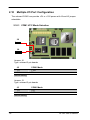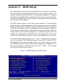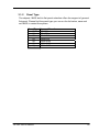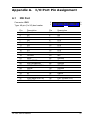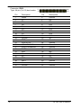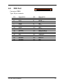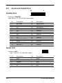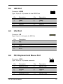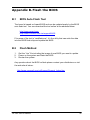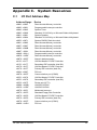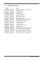
1
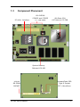
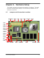
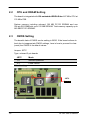
LE-362
User Manual
Edition 1.1
Copyright
Copyright© 2003 - 2004. All rights reserved. This document is copyrighted and
all rights are reserved. The information in this document is subject to change
without prior notice to make improvements to the products.
This document contains proprietary information and protected by copyright.
No part of this document may be reproduced, copied, or translated in any
form or any means without prior written permission of the manufacturer.
All trademarks and/or registered trademarks contains in this document are
property of their respective owners.
Disclaimer
Taiwan Commate Computer Inc. shall not be liable for any incidental or
consequential damages resulting from the performance or use of this product.
Taiwan Commate Computer Inc. does not issue a warranty of any kind,
express or implied, including without limitation implied warranties of
merchantability or fitness for a particular purpose.
The company has the right to revise the manual or include changes in the
specifications of the product described within it at any time without notice and
without obligation to notify any person of such revision or changes.
Trademark
All trademarks are the property of their respective holders.
Any questions please visit our website at http://www.commell.com.tw.
LE-362 User’s Manual
1
Packing List
Hardware
LE-362 Single Board Computer .................................. X 1
Cable Kit
Audio Cable ................................................................ X 1
IDE Flat Cable (UltraDMA/100, 40-pin) ....................... X 1
IDE Flat Cable (UltraDMA/66, 44-pin) ......................... X 1
26-pin slime-type FDD Cable ...................................... X 1
COM Port DB9 ............................................................ X 1
LPT Port DB25 .......................................................... X 1
PS/2 Keyboard and Mouse Cable ............................... X 1
TV-out cable................................................................ X 1
USB Cable ................................................................ X 1
LAN Cable ................................................................. X 1
VGA Port DB15 ......................................................... X 1
Printed Matter and Software
LE-362 User Manual ................................................... X 1
Driver CD .................................................................... X 1
2
LE-362 User’s Manual
Table of Content
Chapter 1.
1.1
1.2
1.3
Introduction .................................................................................. 5
Product Overview ........................................................................ 5
Specifications .............................................................................. 6
Component Placement ................................................................ 9
Chapter 2. Hardware Setup.......................................................................... 11
2.1
2.2
2.3
2.4
2.5
2.6
2.7
2.8
2.9
2.10
Jumpers and Connectors Location............................................ 11
2.1.1
Jumpers Reference..................................................... 12
2.1.2
Connectors Reference ................................................ 13
CPU and DRAM Setting ............................................................ 14
CMOS Setting ........................................................................... 14
Watchdog Timer Setting ............................................................ 15
Embedded Flash Disk ............................................................... 16
Power and Fan Connectors....................................................... 17
VGA Interface ............................................................................ 18
2.7.1
Standard Analog VGA Interface................................... 18
2.7.2
TV-out Interface ........................................................... 19
2.7.3
Digital VGA Interface................................................... 20
Ethernet Interface...................................................................... 22
Audio Interface .......................................................................... 23
Multiple I/O Port Configuration .................................................. 24
2.10.1
2.11
Expansive Bus Interfaces .......................................................... 25
2.11.1
2.12
COM1 VCC Mode Selection ....................................... 24
PC/104-plus Interface ................................................. 25
Switches and Indicators ............................................................ 26
Chapter 3. BIOS Setup ................................................................................. 27
3.1
Flat Panel Type Setting ............................................................. 28
3.1.1
Advanced Chipset Features Screen............................ 28
3.1.2
Panel Type .................................................................. 29
LE-362 User’s Manual
3
Chapter 4. Driver Installation ...................................................................... 31
4.1
4.2
4.3
4.4
4.5
4.6
4.7
Install Board’s Software ............................................................ 31
Install Ultra ATA IDE Driver........................................................ 31
Install VGA Driver...................................................................... 31
Install LAN Driver ...................................................................... 31
Install Audio Driver .................................................................... 31
Link to < Website > Homepage ................................................. 31
Browse this CD ......................................................................... 31
Appendix A.
A.1
A.2
A.3
A.4
A.5
A.6
IDE Port .................................................................................... 33
FDD Port ................................................................................... 35
Serial and Parallel Port ............................................................. 36
USB Port ................................................................................... 37
IrDA Port ................................................................................... 37
PS/2 Keyboard and Mouse Port................................................ 37
Appendix B.
B.1
B.2
Flash the BIOS .......................................................... 39
BIOS Auto Flash Tool ................................................................ 39
Flash Method ............................................................................ 39
Appendix C.
C.1
C.2
C.3
I/O Port Pin Assignment ........................................................ 33
System Resources ................................................................. 41
I/O Port Address Map................................................................ 41
Memory Address Map ............................................................... 42
System IRQ and DMA Resource............................................... 43
C.3.1 IRQ .................................................................................... 43
C.3.2 DMA................................................................................... 44
Contact Information........................................................................................ 45
4
LE-362 User’s Manual
Chapter 1.
1.1
Introduction
Product Overview
The LE-362 Single Board Computer is an all-in-one industrial 3.5” drive-size
little-board computer based on VIA EBGA Eden/C3 embedded / low power
686-level processor. The onboard VIA EBGA Eden CPU offers 667/533/400
MHz of speed at the low voltage to provide the low power embedded
computing platform for low power, an free, mobile and related applied /
embedded computing applications.
LE-362 integrates VIA CLE266 chipset with MPEG II/I decoder, onboard 128
MB PC133 SDRAM, 24-bit TTL flat panel SVGA, TV-out, 10/100BASE-Tx
Fast Ethernet, AC97 3D audio, CompactFlash solid state disk, UltraATA/100
PCI enhanced IDE interfaces, and multiple I/O ports including 1 RS232, 1 LPT
and 1 USB ports. These features make LE-362 be the ideal solution of
multimedia platform, node terminal, transaction station, POS, Kiosk, panel PC,
ATM and embedded application.
Compact Low Profile Board Size
3.5” drive size meets the industrial standard EBX form factor. The onboard
CPU and SDRAM also make LE-362 be the low profile solution for embedded
compact applications.
Advanced Embedded Computing Platform
VIA Eden embedded CPU supports up to 700 MHz at 133 MHz FSB with
onboard 128 MB PC133 SDRAM of system memory for high-end industrial
embedded computing platform with high CPU and memory loading.
Flat Panel SVGA Interface
Integrated VIA/S3 ProSavage flat panel SVGA controller with 24-bit TTL flat
panel interface offers the high 3D performance for LCD-based applications.
Multiple I/O Port Interface
Integrated 1 COM, 1 parallel, 1 USB ports for industrial applications like POS,
Kiosk, Panel PC, ATM and transaction workstation.
LE-362 User’s Manual
5
1.2
Specifications
General Specification
Form Factor
CPU
3.5” drive-size EBX compliant littleboard computer
VIA Eden 667 MHz CPU at 133 MHz FSB
Low power / fan free x86 computing platform
Optional Eden 533/400 or C3 800 MHz CPU for OEM
Chipset
VIA CLE266 with VT8623 and VT8235
MPEG II/I decoder integrated
DRAM
Onboard 128 MB PC133 SDRAM
1 x 144-pin SO-DIMM slot supports 512 MB PC133
SDRAM
Total memory capacity up to 640 MB PC133 SDRAM
BIOS
Phoenix-Award 2Mb PnP flash BIOS
Enhanced IDE
PCI enhanced IDE interface supports dual ports up to 4
ATAPI devices with UltraATA/100 supported
One 40-pin box header connector
One 44-pin box header connector
Green Function
Power saving mode supported in BIOS with DOZE,
STANDBY and SUSPEND modes. ACPI version 1.0 and
APM version 1.2 compliant
Watchdog Timer
256-level system reset programmable watchdog timer
Real Time Clock
VIA VT8235 built-in RTC with lithium battery
Multi-I/O Ports
Chipset
Serial Port
Winbond W83697HF for COM1, FFD and LPT Ports
one RS-232 serial port COM1
with 16C550 compatible UART and 16 bytes FIFO
+5V/+12V power output for RS232 peripherals
6
USB Port
two USB ports with USB version 2.0 compliant
Parallel Port
one bi-direction parallel port with SPP/ECP/EPP mode
FDD
One FPC connector to support slime type floppy
IrDA Port
1 x IrDA compliant Infrared interface supports SIR
K/B & Mouse
PS/2 keyboard and mouse ports
LE-362 User’s Manual
Solid State Disk Interface
Flash Type
CompactFlash Type-II for CFC (Compact Flash Card)
or IBM MicroDrive
Capacity
Up to 1 GB flash memory
Display Interface
Chipset
VIA CLE266 chipset with integrated S3
ProSavage™ 8X AGP 3D SVGA controller
Video Memory
8/16/32/64MB of video memory shared with system
memory, selectable in BIOS
Display Type
24-bit TTL flat panel / CRT and LCD monitor at VGA, SVGA,
XGA, SXGA, UXGA
TV-out Interface
chipset
Integrated VT1622M to support NTSC or PAL TV
display
type
One 2x5-pin header to support S-video & Composite
output
Ethernet Interface
Chipset
One 10/100BASE-Tx Fast Ethernet LAN interfaces with
VIA VT6103 PHY controller
Type
10Base-T / 100Base-TX, auto-switching Fast Ethernet,
full duplex, IEEE802.3U compliant
Audio Interface
Chipset
VIA VT8235 integrated AC97 3D audio controller with
onboard Realtek ALC201A codec
Interface
Line-in, line-out, CD-in, Mic-out
Connector
Onboard 10-pin header connector for line-in, line-out
and Mic-out
LE-362 User’s Manual
7
Expansive Interface
PC/104-plus
One PC/104-plus interface with 32-bit PCI-based
Power and Environment
Power Req.
+5V, +12V DC input on standard 4-pin AT connector
ATX Function
One 3-pin ATX interface with 5V standby
Dimension
146 x 101 mm (L x W), standard EBX size
Temperature
Operating within 0 ~ 60oC (32 ~ 140oF)
Storage within -20 ~ 85oC (-4 ~ 185oF)
Ordering Code
LE-362VL-P
With Eden 667 MHz CPU ,SVGA, Audio, LAN, Compact
Flash, PC/104+ Interface and 1 COM Ports, 1 LPT and 1
USB
LE-362VL-128
Same as LE-362VL-P but with 128MB SDRAM
onboard
Online product information detail and updates are available on http://www,commell.com.tw
8
LE-362 User’s Manual
1.3
Component Placement
VIA CLE266
PC/104+ Interface
VT8623 and VT8235
VIA Eden CPU
TTL Flat Panel
667 MHz @ 133 FSB
System Memory
Onboard 128 MB
144-pin
CompactFlash SSD
SO-DIMM
SOCKET
Type-II Socket
CFC / MicroDrive
LE-362 User’s Manual
9
Notes
10
(This page left blank intentionally)
LE-362 User’s Manual
Chapter 2.
Hardware Setup
This chapter contains the information for installation of hardware. The install
procedure includes jumper settings, CPU and memory installation, fan, I/O
and panel connections.
2.1
Jumpers and Connectors Location
CHASFAN
USB1
LCD1
JLCD
JRTC
TVOUT1
VGA1
VIO1
LAN1
CON2
CDIN
JAUDIO
KBMS1
COM1
JWOL
JFRNT
JIR
ATX1
J2 J3
NB FDD
LE-362 User’s Manual
IDE2
PRINTER
IDE1
CPUFAN
CON3
11
2.1.1
12
Jumpers Reference
Jumper
JRTC
Function
COMS Setting
J2
J3
VIO
JLCD
COM1 pin-1 Voltage setting
COM1 pin-9 Voltage setting
PC/104+ Voltage setting for V/IO
Flat Panel’s Voltage Setting
Section
2.3
2.10
2.10
2.11
2.7.2
LE-362 User’s Manual
2.1.2
Connectors Reference
Connector
DIMM1
IDE1
IDE2
NB FDD
USB1
CFD1
KBMS1
JIR
CON3
ATX1
JFRNT
CPUFAN
CHASFAN
VGA1
LCD1
JAUDIO
CDIN
LAN1
CN2
TVOUT1
LE-362 User’s Manual
Function
144-pin SO-DIMM Slot
40-pin Primary IDE Port
44-pin Secondary IDE Port
26-pin slime-type FDD Port
10-pin 1st / 2nd USB Port
Compact Flash Socket
10-pin PS/2 Keyboard / Mouse Connector
5-pin SIR IrDA Port
4-pin AT Power Connector
3-pin ATX Signal Connector
10-pin Switch and Indicator Connector
3-pin CPU Fan Connector
3-pin System Fan Connector
16-pin Internal VGA Port
40-pin TTL Flat Panel Interface
10-pin Audio Port
4-pin CD-in Interface
10-pin Primary LAN Port Connector
104-pin PC/104+ Connector
10-pin TV-out Connector
Remark
Standard
Standard
Standard
Standard
Standard
Standard
Standard
Standard
Standard
Standard
Standard
Standard
Standard
Standard
Standard
Standard
Standard
Standard
Standard
Standard
13
2.2
CPU and DRAM Setting
The board is integrated with VIA embedded EBGA Eden 667 MHz CPU at
133 MHz FSB.
System memory including onboard 128 MB PC133 SDRAM and one
144-pin SO-DIMM slot up to 512 MB SDRAM. Total memory capacity up to
640 MB PC133 SDRAM.
2.3
CMOS Setting
The board’s data of CMOS can be setting in BIOS. If the board refuses to
boot due to inappropriate CMOS settings, here is how to proceed to clear
(reset) the CMOS to its default values.
Jumper: JRTC
Type: onboard 3-pin header
JRTC
Mode
1-2
2-3
Normal Operation
Clear CMOS
Default setting
JRTC
3
14
1
LE-362 User’s Manual
2.4
Watchdog Timer Setting
The watchdog timer makes the systems auto-reset while it stop to work for
a period.
Program Sample
Watchdog timer setup as system reset with 5 second of timeout
4E, 87
4E, 87
4E, 07
Select Logical Device 8
4F, 08
4E, 30
Set Watchdog Active
4F, 01
4E, F3
Set Count as Second*
4F, 00
4E, F4
Set as 5 Second
4F, 05
* Minute: bit 3 = 1; Second: bit 3 = 0
LE-362 User’s Manual
15
2.5
Embedded Flash Disk
The board supports both IDE-based DiskOnModule and CompactFlash
embedded Solid State Disk (SSD).
Please note that this board doesn’t provide VCC on IDE1, please use external
power Connector with DiskOnModule.
CompactFlash SSD
Type-II Socket
CFC / MicroDrive
16
LE-362 User’s Manual
2.6
Power and Fan Connectors
CHASFAN
1
CPUFAN
3
123
CN3
1
4
1
ATX1
3
Connector: CN3
Type: 4-pin AT Power Connector
Pin
1
2
3
4
Description
+12V
Ground
Ground
+5V
Cable Color Reference
Yellow
Black
Black
Red
Connector: ATX1
Type: 3-pin ATX Function Connector
Pin
1
Description
5V Standby
Pin
2
Description
Ground
Pin
3
Description
Power On
Connector: SYSFAN, CPUFAN
Type: 3-pin Fan Power Wafer Connector
Pin Description
1
Ground
LE-362 User’s Manual
Pin
2
Description
+12V
Pin
3
Description
Fan Control
17
2.7
VGA Interface
2.7.1
Standard Analog VGA Interface
The board is integrated with VIA CLE266 chipset’s built-in 8xAGP S3
ProSavage™ VGA accelerator with 3D/2D engine and 64 MB of video
memory shared with system memory.
VGA1
1
16
Connector: VGA1
Type: 16-pin header
Pin
1
3
5
7
9
11
13
15
18
Description
Red
Blue
Ground
Ground
N/C / Vcc
N/C
HSYNC
Clock
Pin
2
4
6
8
10
12
14
16
Description
Green
N/C
Ground
Ground
Ground
Data
VSYNC
N/C
LE-362 User’s Manual
2.7.2 TV-out Interface
The board integrates with VIA VT1622M TV codec, supports NTSC/PAL TV
format with S-Video and RCA output.
Connector: TVOUT1
Connector type: onboard 2 x 5 pin header, pitch = 2.54mm
Pin
1
3
5
7
9
Description
Ground
Ground
Ground
Ground
Ground
Pin
2
4
6
8
10
Description
DAC_A
Y_E
C_E
CVBS_E
CSO
1
TVOUT1
10
LE-362 User’s Manual
19
2.7.3
Digital VGA Interface
The board’s digital video interface provides 24-bit TTL interface of flat
panel. The digital video interfaces used BIOS selectable 8/16/32/64 MB of
video memory shared with system memory.
LCD1
40
1
1
3
JLCD
Jumper: JLCD
Type: onboard 3-pin (1 x 3) header
JLCD
LCD Voltage Setting
1-2
2-3
+3.3V
+5V
Default setting
20
LE-362 User’s Manual
Connector: LCD1
Type: onboard 40-pin (2 x 20) 2.0 pitch header
Pin
1
3
5
7
9
11
13
15
17
19
21
23
25
27
29
31
33
35
37
39
LE-362 User’s Manual
Signal
+12V
GND
VCC (LCD)
BLON
P0
P2
P4
P6
P8
P10
P12
P14
P16
P18
P20
P22
N/C
SHFCLK
DATAENA
GND
Pin
2
4
6
8
10
12
14
16
18
20
22
24
26
28
30
32
34
36
38
40
Signal
+12V
GND
ENAVDD
GND
P1
P3
P5
P7
P9
P11
P13
P15
P17
P19
P21
P23
N/C
VS
HS
ENABKL
21
2.8
Ethernet Interface
The board integrated with 10/100BASE-TX Fast Ethernet interface at the type
of 10Base-T/100Base-TX auto-switching Fast Ethernet with full duplex and
IEEE 802.3U compliant. The LAN controller, VIA VT6103 PHY provides the
powerful Fast Ethernet interface with embedded operating system (OS)
supported, green function (power saving mode / wake-on-LAN) and advanced
network management functions.
LAN1
14
1
Connector: LAN1
Type: 14-pin header connector (1~10 pin for LAN signal & 11~14 for LED)
Pin
1
3
5
7
9
11
13
22
Description
TX+
RX+
N/C
N/C
Ground
ACT
SP100
Pin
2
4
6
8
10
12
14
Description
TXN/C
RXN/C
Ground
Vcc
Vcc
LE-362 User’s Manual
2.9
Audio Interface
The board integrates with AC97 3D audio interface VIA VT8235 and Realtek
ALC201A codec that provides line-in, line-out, Mic-in and CD-in interfaces for
industrial applications with audio function.
CDIN
1
2
3
4
JAUDIO
1
10
Connector: JAUDIO
Type: 10-pin header
Pin
1
3
5
7
9
Description
Line – Right
Line – Left
MIC
N/C
Line Out – Right
Pin
2
4
6
8
10
Description
Ground
MIC
Ground
Line Out – Left
Ground
Connector: CDIN
Type: 4-pin header
Pin
1
2
3
4
Description
CD – Left
Ground
Ground
CD – Right
LE-362 User’s Manual
23
2.10
Multiple I/O Port Configuration
The onboard COM1 can provide +5V or +12V power with J2 and J3 jumper
selectable.
2.10.1 COM1 VCC Mode Selection
J3
1
3
J2
1
3
Jumper: J2
Type: onboard 3-pin header
J2
COM1 Mode
1-2
2-3
+12V
RI
Default setting
Jumper: J3
Type: onboard 3-pin header
J3
1-2
2-3
Default setting
24
COM1 Mode
+5V
DCD
LE-362 User’s Manual
2.11
Expansive Bus Interfaces
The board offers PCI/ISA expansive bus interfaces with one PC/104-plus
connector.
2.11.1 PC/104-plus Interface
The onboard PC/104-plus interface includes 32-bit PCI-based 120-pin
PC/104-plus interface. There is one set of bus master PCI signal is
supported on the onboard PC/104-plus interface. More information about
PC/104-plus interface is available at: http://www.pc104.org/
VIO1
3
1
Jumper: VIO1
Type: onboard 3-pin header
VIO1
1-2
2-3
PC/104+ Mode
3.3V Standby
5V Standby
Default setting
LE-362 User’s Manual
25
2.12
Switches and Indicators
JFRNT
10
9
2
1
Connector: JFRNT
Type: onboard 10-pin header
Function
IDE LED
Reset
26
Signal
PIN
Signal
Vcc (+)
1
2
(+) Vcc
Active
3
4
N/C
Reset
5
6
GND
GND
7
8
N/C
PW_BN
9
10
GND
Function
Power
LED
Power
Button
LE-362 User’s Manual
Chapter 3.
BIOS Setup
The single board computer uses the Award BIOS for the system configuration.
The Award BIOS in the single board computer is a customized version of the
industrial standard BIOS for IBM PC AT-compatible computers. It supports
Intel x86 and compatible CPU architecture based processors and computers.
The BIOS provides critical low-level support for the system central processing,
memory and I/O sub-systems.
The BIOS setup program of the single board computer let the customers
modify the basic configuration setting. The settings are stored in a dedicated
battery-backed memory, NVRAM, retains the information when the power is
turned off. If the battery runs out of the power, then the settings of BIOS will
come back to the default setting. The BIOS section of the manual is subject to
change without notice and is provided here for reference purpose only. The
settings and configurations of the BIOS are current at the time of print, and
therefore they may not be exactly the same as that displayed on your screen.
To activate CMOS Setup program, press <DEL> key immediately after you
turn on the system. The following message “Press DEL to enter SETUP”
should appear in the lower left hand corner of your screen. When you enter
the CMOS Setup Utility, the Main Menu will be displayed as Figure 3-1. You
can use arrow keys to select your function, press <Enter> key to accept
the selection and enter the sub-menu.
Figure 3-1. CMOS Setup Utility Main Screen
LE-362 User’s Manual
27
3.1
Flat Panel Type Setting
3.1.1
Advanced Chipset Features Screen
The selection of display type for flat panel depends on the LCD display you
use. Please entry the “Advanced Chipset Features” screen on the main
screen and find the item of “Panel Type”, and set it with the specification of
the flat panel.
Figure 3.2 - Advanced Chipset Features Screen
Phoenix – AwardBIOS CMOS Setup Utility
28
LE-362 User’s Manual
3.1.2
Panel Type
The chipset / BIOS built-in flat panel selection offers the support of general
flat panel. Please find the panel type you use on the list below, save and
exit BIOS to restart the system.
Panel Type
00
01
02
03
04
05
06
Support Function
640x480
800x600
1024x768
1280x768
1280x1024
1400x1500
1600x1200
Default Setting
LE-362 User’s Manual
29
Notes
30
(This page left blank intentionally)
LE-362 User’s Manual
Chapter 4.
Driver Installation
The driver CD offers auto-run menu. It will detect and select the type of single
board computer and helps you install the drivers automatically.
4.1
Install Board’s Software
The selection helps you install the drivers of chipset. It will detect your version
of OS automatically.
4.2
Install Ultra ATA IDE Driver
The selection helps you to install the driver of IDE interface.
4.3
Install VGA Driver
The selection helps you to install the driver of onboard VGA interface.
4.4
Install LAN Driver
The selection helps you to install the driver of onboard LAN interface.
4.5
Install Audio Driver
The selection helps you to install the driver of onboard audio interface.
4.6
Link to < Website > Homepage
The selection help you to link to the website to find the updated technical
documents and download directly.
4.7
Browse this CD
The selection helps you to find the drivers in this CD directly.
LE-362 User’s Manual
31
Notes
32
(This page left blank intentionally)
LE-362 User’s Manual
Appendix A.
A.1
I/O Port Pin Assignment
IDE Port
Connector: IDE1
Type: 40-pin (2 x 20) box header
Pin
1
3
5
7
9
11
13
15
17
19
21
23
25
27
29
31
33
35
37
39
Description
Reset
D7
D6
D5
D4
D3
D2
D1
D0
Ground
REQ
IOW-/STOP
IOR-/HDMARDY
IORDY/DDMARDY
DACKIRQ
A1
A0
CS0 (MASTER CS)
LED ACT-
LE-362 User’s Manual
2
1
Pin
2
4
6
8
10
12
14
16
18
20
22
24
26
28
30
32
34
36
38
40
40
39
Description
Ground
D8
D9
D10
D11
D12
D13
D14
D15
N/C
Ground
Ground
Ground
IDESEL
Ground
N/C
CBLID
A2
CS1 (SLAVE CS)
Ground
33
Connector: IDE2
Type: 44-pin (2 x 22) box header
Pin
1
3
5
7
9
11
13
15
17
19
21
23
25
27
29
31
33
35
37
39
41
43
34
Description
Reset
D7
D6
D5
D4
D3
D2
D1
D0
Ground
REQ
IOW-/STOP
IOR-/HDMARDY
IORDY/DDMARDY
DACKIRQ
A1
A0
CS1
ASP1
Vcc
Ground
44
43
2
1
Pin
2
4
6
8
10
12
14
16
18
20
22
24
26
28
30
32
34
36
38
40
42
44
Description
Ground
D8
D9
D10
D11
D12
D13
D14
D15
N/C
Ground
Ground
Ground
Ground
Ground
N/C
SD
A2
CS3
Ground
Vcc
Ground
LE-362 User’s Manual
A.2
FDD Port
Connector: FDD1
Type: 26-pin connector
Pin
1
3
5
7
9
11
13
15
17
19
21
23
25
Description
VCC
VCC
VCC
DRV1
MTR1
RPM
N/C
Ground
Ground
N/C
N/C
Ground
Ground
LE-362 User’s Manual
Pin
2
4
6
8
10
12
14
16
18
20
22
24
26
Description
INDEX
DRV0
DSKCHG
N/C
MTR0
DIR
STEP
WRITE DATA
WRITE GATE
TRACK 0
WRPTR
RDATASEL
35
A.3
Serial and Parallel Port
13
1
26
14
Parallel Port
Connector: PRINTER
Type: 26-pin (2 x 13) 2.54-pitch box header
Pin
1
2
3
4
5
6
7
8
9
10
11
12
13
Description
STROBED0
D1
D2
D3
D4
D5
D6
D7
ACKNOWLEDGEBUSY
PAPER EMPTY
SELECT+
Pin
14
15
16
17
18
19
20
21
22
23
24
25
26
Description
AUTO FEEDERRORINITIALIZESELECT INPUTGround
Ground
Ground
Ground
Ground
Ground
Ground
Ground
Ground
Serial Port
1
2
Connector: COM1
Type: 10-pin (2 x 5) 2.54-pitch header
Pin
1
3
5
7
9
36
Description
DCD
TXD
Ground
RTS
RI
Pin
2
4
6
8
10
Description
RXD
DTR
DSR
CTS
N/C
LE-362 User’s Manual
A.4
USB Port
2
Connector: JUSB1
Type: 10-pin (2 x 5) header for dual USB Ports
Pin
1
3
5
7
9
A.5
Description
Vcc
Data1Data1+
Ground
N/C
Pin
2
4
6
8
10
1
9
Description
Vcc
Data0Data0+
Ground
Ground
IrDA Port
Connector: JIR
Type: 5-pin (1 x 5) header for SIR Port
Pin
1
2
3
4
5
A.6
10
1
5
Description
Vcc
N/C
IRRX
Ground
IRTX
PS/2 Keyboard and Mouse Port
Connector: JPS2
Type: 10-pin (2 x 5) header connector
Pin
1
3
5
7
9
Description
Keyboard Data
N/C
Ground
VCC
Keyboard Clock
LE-362 User’s Manual
Pin
2
4
6
8
10
9
1
10
2
Description
Mouse Data
N/C
Ground
VCC
Mouse Clock
37
Notes
38
(This page left blank intentionally)
LE-362 User’s Manual
Appendix B. Flash the BIOS
B.1
BIOS Auto Flash Tool
The board is based on Award BIOS and can be updated easily by the BIOS
auto flash tool. You can download the tool online at the address below:
http://www.award.com
http://www.commell.com.tw/support/BIOS
File name of the tool is “awdflash.exe”, it’s the utility that can write the data
into the BIOS flash ship and update the BIOS.
B.2
1.
2.
3.
Flash Method
Get the “.bin” file including the image of new BIOS you want to update.
Power on the system and flash the BIOS.
Re-star the system.
Any question about the BIOS re-flash please contact your distributors or visit
the web-site at below:
http://www.commell.com.tw/Support/Support_Index.htm
LE-362 User’s Manual
39
Notes
40
(This page left blank intentionally)
LE-362 User’s Manual
Appendix C.
C.1
System Resources
I/O Port Address Map
Address Range
Device
x0000 - x000F
Direct Access Memory controller
x0020 - x0021
Programmable interrupt controller
x0040 - x0043
System Timer
x0060 - x0060
Standard 101/102-Key or Microsoft Natural Keyboard
x0061 - x0061
System Speaker
x0064 - x0064
Standard 101/102-Key or Microsoft Natural Keyboard
x0070 - x0071
System CMOS/ Real time clock
x0081 - x0083
Direct Access Memory controller
x0087 - x0087
Direct Access Memory controller
x0089 - x008B
Direct Access Memory controller
x008F - x0091
Direct Access Memory controller
x00A0 - x00A1
Programmable interrupt controller
x00C0 - x00DF
Direct Access Memory controller
x00F0 - x00FF
Numeric data processor
x0170 - x0177
VIA Bus Master PCI IDE Controller
x0170 - x0177
Secondary IDE controller (dual fifo)
x01F0 - x01F7
VIA Bus Master PCI IDE Controller
x01F0 - x01F7
Primary IDE controller (dual fifo)
x0294 - x0297
PCI bus
x02F8 - x02FF
Communication port (COM2)
x0376 - x0376
VIA Bus Master PCI IDE Controller
x0376 - x0376
Secondary IDE controller (dual fifo)
x0378 - x037F
Printer port (LPT1)
x03B0 - x03BB
VIA/S3G CLE266
x03C0 - x03DF
VIA/S3G CLE266
x03F0 - x03F1
Mainboard resource
x03F2 - x03F5
Standard Floppy Disk Controller
x03F6 - x03F6
VIA Bus Master PCI IDE Controller
x03F6 - x03F6
Primary IDE controller (dual fifo)
x03F8 - x03FF
Communication port (COM1)
x04D0 - x04D1
PCI bus
LE-362 User’s Manual
41
C.2
Memory Address Map
Range
Device
x00000000 - x0009FFFF
System board extension for PnP BIOS
x000A0000 - x000AFFFF
VIA/S3G CLE266
x000B0000 - x000BFFFF
VIA/S3G CLE266
x000C0000 - x000CF7FF
VIA/S3G CLE266
x000CF800 - x000CFFFF
Motherboard resource
x000F0000 - x000F3FFF
Motherboard resource
x000F4000 - x000F7FFF
Motherboard resource
x000F8000 - x000FFFFF
Motherboard resource
x00100000 - x00FFFFFF
System board extension for PnP BIOS
xE0000000 - xE3FFFFFF
PCI standard host CPU bridge
xE4000000 - xE7FFFFFF
VIA CPU to AGP Controller
xE4000000 - xE7FFFFFF
VIA/S3G CLE266
xE8000000 - xE8FFFFFF
VIA/S3G CLE266
xE8000000 - xE9FFFFFF
VIA CPU to AGP Controller
xE9000000 - xE900FFFF
VIA/S3G CLE266
xEA000000 - xEA0000FF
VIA PCI to USB Enhanced Host Controller
xEA001000 - xEA0010FF
VIA Rhine II Fast Ethernet Adapter
xFEC00000 - xFEC0FFFF
System board extension for PnP BIOS
xFEE00000 - xFEE0FFFF
System board extension for PnP BIOS
xFFFE0000 - xFFFFFFFF
System board extension for PnP BIOS
42
LE-362 User’s Manual
C.3
System IRQ and DMA Resource
C.3.1 IRQ
IRQ Number
Device
0
System Timer
1
Standard 101/102-Key or Microsoft Natural Keyboard
2
Programmable interrupt controller
3
Communication port (COM2)
4
Communication port (COM1)
5
VIA PCI to USB Enhanced Host Controller
5
IRQ Holder for PCI Steering
6
Standard floppy disk controller
7
Printer port (LPT1)
8
System CMOS/ Real time clock
9
VIA Tech 3038 PCI to USB Universal Host Controller
9
IRQ Holder for PCI Steering
10
Realtek AC'97 Audio for VIA (R) Audio Controller
10
VIA Tech 3038 PCI to USB Universal Host Controller
10
IRQ Holder for PCI Steering
11
VIA Rhine II Fast Ethernet Adapter
11
VIA Tech 3038 PCI to USB Universal Host Controller
11
VIA/S3G CLE266
11
IRQ Holder for PCI Steering
12
PS/2 compatible mouse port
13
Numeric Data Proccesor
14
Primary IDE controller (dual fifo)
14
VIA Bus Master PCI IDE Controller
15
Secondary IDE controller (dual fifo)
15
VIA Bus Master PCI IDE Controller
LE-362 User’s Manual
43
C.3.2 DMA
Channel
44
Device
0
(free)
1
(free)
2
Standard Floppy Disk Controller
3
(free)
4
Direct memory access controller
5
(free)
6
(free)
7
(free)
LE-362 User’s Manual
Contact Information
Any advice or comment about our products and service, or anything we can help
you please don’t hesitate to contact with us. We will do our best to support you
for your products, projects and business.
COMMELL Industrial Computer
Taiwan Commate Computer Inc.
COMMELL
www.commell.com.tw
Your Embedded Applied Computer Partner
Address
8F, No. 94, Sec. 1, Shin Tai Wu Rd., Shi Chih
Taipei Hsien, Taiwan
TEL
+886-2-26963909
FAX
+886-2-26963911
Website
http://www.commell.com.tw
E-mail
[email protected] (General Information)
[email protected] (Technical Support)
Authorized Distributor
LE-362 User’s Manual
45