1
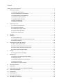
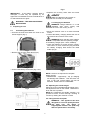
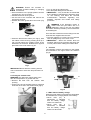
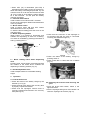
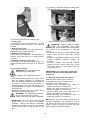
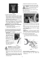
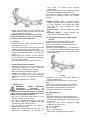
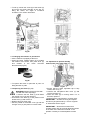
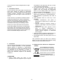
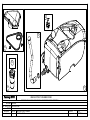
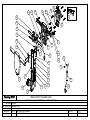
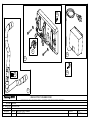
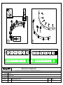
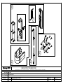
ORBIS BATTERY
SCRUBBER DRYER
OPERATOR MANUAL
Clemas & Co. Unit 5 Ashchurch Business Centre, Alexandra Way, Tewkesbury,
Gloucestershire, GL20 8NB.
Tel: 01684 850777
Fax: 01684 850707
Email: [email protected]
Web: www.clemas.co.uk
Contents
Getting to know the machine ................................................................................................................... 4
1
Product Information......................................................................................................................... 5
1.1 Important Safety Advice ....................................................................................................... 5
1.2 Non intended use of the machine ........................................................................................ 5
1.3 General warnings about batteries ........................................................................................ 6
1.4 Guidelines for the operator................................................................................................... 6
1.5 Transporting the machine..................................................................................................... 6
1.6 Symbols & Markings............................................................................................................. 6
1.7 Electrical connection ............................................................................................................ 6
2
Preparing for use ............................................................................................................................ 7
2.1 Connecting the batteries ...................................................................................................... 7
2.2 Charging the batteries .......................................................................................................... 7
2.3 Adjusting the handle height .................................................................................................. 7
2.4 Fitting brushes and pads ...................................................................................................... 7
2.5 Filling the solution tank......................................................................................................... 8
3
Controls........................................................................................................................................... 8
4
Operation ........................................................................................................................................ 9
4.1 Checks before use ............................................................................................................... 9
4.2 Preparing the machine and choosing the cycle ................................................................... 9
4.3 Using the machine.............................................................................................................. 10
5
Warnings while using the machine ............................................................................................... 10
5.1 When cleaning is finished................................................................................................... 11
5.2 Draining and cleaning the recovery tank ............................................................................ 11
5.3 Draining and cleaning the solution tank ............................................................................. 11
5.4 Cleaning the squeegee blades........................................................................................... 11
6
Storage ......................................................................................................................................... 12
6.1 Prolonged machine standstill ............................................................................................. 12
7
Maintenance ................................................................................................................................. 12
7.1 Replacing the squeegee rubber blades ............................................................................. 12
7.2 Squeegee set up ................................................................................................................ 12
7.3 Changing the brushes or pad drivers ................................................................................. 13
7.4 Replacing the fuses ........................................................................................................... 13
7.5 Operations to perform weekly ............................................................................................ 13
8
After Sales Service ....................................................................................................................... 14
9
Guarantee ..................................................................................................................................... 14
10
Waste Electrical & Electronic Equipment (WEEE) ....................................................................... 14
11
Technical specification.................................................................................................................. 15
12
Accessories................................................................................................................................... 15
13
Fault diagnosis.............................................................................................................................. 16
14
Parts Lists & Diagrams ................................................................................................................. 18
15
Declaration of Conformity ............................................................................................................. 35
3
Getting to know the machine
1
2
20
4
7
9
3
5
6
8
11
13
12
10
14
16
17
18
19
1. Handle
11. Brush guard
2. Control panel
12. Brush
3. Squeegee lifting lever
13. Squeegee
4. Lever for starting brush rotation and/or
14. Recovery tank drain hose
dispensing water
15. Vacuum hose
5. Handle adjusting lever
16. Battery charger lead
6. Recovery tank
17. Battery charger indicator
7. Recovery tank lid
18. Water regulation tap
8. Solution tank
19. Water filter
9. Solution tank filling opening
20. Solution filling hose
10. Wheels
4
15
IMPORTANT
BEFORE USE READ THESE INSTRUCTIONS AND RETAIN FOR FUTURE REFERENCE
1
• Before using the appliance, check that the
mains power voltage corresponds with the
voltage shown on the rating plate.
• All parts are to be positioned as indicated in the
instructions before using the machine.
• Do not operate the machine if it malfunctions or
is damaged in any way. Contact an authorised
service agent for repair or adjustment.
• Do not operate switches or touch the mains
plug with wet hands as this may cause electric
shock.
• When unplugging pull the plug, not the supply
cord.
• Do not pull or carry by cord, use cord as a
handle, close a door on cord, or pull around
sharp edges or corners.
• Keep hair, loose clothing, fingers and all parts
of body away from openings and moving parts.
• Keep cord away from heated surfaces.
• Do not use where hazardous dust is present.
• Do not use in an explosive atmosphere.
• Do not pick up oil or other flammable material.
• Do not operate the machine when connected to
the mains electrical supply.
• The battery charging lead must be regularly
inspected for signs of damage. If the lead is
damaged, it shall only be replaced by the
manufacturer, its service agent or a similar
qualified person in order to avoid a hazard.
• Only replace the supply cord with the type
specified in the instruction manual.
• Do not charge the machine with a damaged
battery charging lead or plug, or after the
machine malfunctions or is damaged in any
way. Contact an authorised Service Agent for
repair or adjustment.
• The plug of the charger cable must be removed
from the socket-outlet before commencing
cleaning of the machine or undertaking
maintenance operations.
• When re-charging ensure the area is
sufficiently ventilated.
• Take care when using a machine near the top
of stairs to avoid overbalancing.
Product Information
These commercial floor treatment machines are
designed for the scrubbing of hard floors in
indoor areas.
Maintenance free (gel) batteries must be used
which provide up to 80 minutes running time. A
battery life indicator allows the operator to assess
the degree of battery life available, and an on
board battery charger provides convenient
charging.
This machine must only be used for the
manufacturer’s approved application. Do not
use the machine where it is suspected that the
floor surface contains health endangering dust or
debris such as asbestos or chemical waste. If
this is suspected do not proceed, contact your
supervisor, supplier or Truvox International for
advice.
The following instructions contain important
information about the machine and safety advice
for the operator.
Equipment must be operated, serviced and
maintained
in
accordance
with
the
manufacturer’s instructions. If in doubt contact
the supplier of your machine.
These instructions are valid for the following
models:
Orbis Battery Scrubber – OBS38130…
1.1 Important Safety Advice
When using electrical equipment basic safety
precautions should be followed including the
following.
• Read all instructions carefully before use.
• Please note that the safety information
described in the manual supplements and does
not replace standards in force in the country in
which the machine is used.
• This appliance is suitable for commercial use,
for example in hotels, schools, hospitals,
factories, shops, offices, rental businesses and
other than normal housekeeping purposes.
• This machine is not intended for use by
persons (including children) with reduced
physical, sensory or mental capabilities, or lack
of experience and knowledge, unless they
have been given supervision or instruction
concerning use of the machine by a person
responsible for their safety.
• Keep children and unauthorised persons away
from the machine when in use.
1.2 Non intended use of the machine
WARNING
• Washing floors with water which is
hotter than 50°C;
• Using diesel/petrol or corrosive detergents to
wash floors;
• Washing and vacuuming of corrosive,
flammable and/or explosive liquids, even if
diluted.
5
WARNING Ensure the machine is switched off
before adding or changing accessories.
1.3 General warnings about batteries
WARNING Use appropriate personal
protection equipment to avoid contact
with the skin (see standards in force in
the country in which the machine is used).
• Do not inhale the vapour: it is dangerous.
• It is forbidden to smoke and/or use naked
flames within 2 metres of the battery during
charging, in the charging area and while the
battery is cooling after charging.
• Report any liquid leaking from the battery:
leaks are dangerous and highly polluting.
1.5 Transporting the machine
CAUTION - THIS MACHINE IS HEAVY
Do not attempt to lift the machine
without mechanical assistance.
CAUTION – Incorrect lifting techniques
may result in personal injury, where
applicable do not lift large and heavy machines
without assistance. We advise that the manual
handling regulations are followed.
Please refer to the technical table for details on
weight of machine.
WARNING In the event of a fire, use
approved powder extinguishers only; do
NOT use water to put out the fire.
When transporting the machine ensure that all
components, tanks and removable parts are
securely fastened, and that the battery charging
lead and plug are not trailing. Detach hose and
wand from machine where applicable.
1.4 Guidelines for the operator
WARNING
Operators must be fully trained in the use
of the machine in accordance with these
instructions, able to perform user maintenance
and the correct selection of accessories.
• Operators should be physically capable to
manoeuvre, transport and operate the
machine.
• Operators should be able to recognise unusual
operation of the machine and report any
problems.
• Only use the machine on firm level surfaces,
no more than a 2% slope.
• Wear suitable footwear to avoid slipping.
• Wear suitable clothing to keep dry and warm.
• Where possible implement job rotation and
adequate rest periods to avoid continuous use
of the same muscles.
• Do not leave machine running unattended.
• Do not smoke when using the machine.
• Do not put any objects into openings. Do not
use with any opening blocked: keep free of
dust, debris, hair, or anything that may reduce
air flow.
• Keep hands and feet well clear of rotating pads
and brushes.
To move the machine to the work area lock
handle and tilt backwards to raise the front off the
floor, and wheel into position.
CAUTION – Bumping over thresholds,
kerbs and similar obstacles can damage
the machine. Small obstacles can be
overcome by pulling the machine
backwards.
1.6 Symbols & Markings
In order to highlight information and procedures
regarding safety, maintenance etc, the following
symbols have been adopted in the manual:
WARNING
Earth symbol
CAUTION - This machine is for indoor
use only and should not be used or
stored outdoors or in wet conditions.
1.7 Electrical connection
Before connecting the machine to the power
supply, check that your supply voltage
corresponds with that marked on the rating label.
CAUTION - If it is suspected that there is
hazardous dust or flammable materials
stop cleaning the area immediately and
consult your superior.
UK only
The supply cord is fitted with a plug containing a
3 amp fuse. Should the fuse require replacement
it must only be replaced by a 3 amp fuse
conforming to BS1362, and the fuse cover must
be refitted. If the fuse cover is lost the plug must
not be used until the correct replacement cover is
fitted.
WARNING Only use accessories and
spare parts provided with the machine or
those approved by the manufacturer.
The use of other accessories may impair
the safety of the machine.
6
Fig 4
• Replace the recovery water tank and screw
into place.
WARNING
Make sure that the mains system is
equipped with an RCD (circuit breaker).
IMPORTANT - If the battery charging lead is
damaged, it must only be replaced by an
approved cord available from the manufacturer or
an authorised service agent.
WARNING – THIS APPLIANCE MUST
BE EARTHED
2
2.1
2.2 Charging the batteries
WARNING Charge batteries in a well
ventilated area which comply with
standards in force in the country of use.
Preparing for use
Connecting the batteries
• Move the machine close to a mains electrical
socket.
• Unwind the battery charging lead at the rear of
the machine and connect to the outlet.
• Unscrew the bolts that fasten the tank to the
handle support (Fig 1).
WARNING Check that the mains voltage
is compatible with the operating voltage
of the battery charger (220 – 240V, 50/60Hz).
• Leave the batteries to charge until the “Green”
LED comes on, then remove the plug and wind
the battery charging lead around the cable
holder (Fig 5).
Fig 1
• Remove the recovery water tank (Fig 2).
Fig 2
• Connect the battery connectors (Fig 3 & 4).
Fig 5
NOTE: 10 hours are required for complete
battery charge.
• IMPORTANT - Opportunity / top up charging
will damage the batteries. This will cause run
time to fall and overall battery life will be
affected. AVOID TOP UP CHARGING.
2.3 Adjusting the handle height
Select the most comfortable handle height using
the adjustment lever on the handle. Release the
lever and lock in position.
NOTE: By positioning the handle vertically, it is
possible to effect a more thorough cleaning of
corners by rotating the machine on itself.
Fig 3
2.4 Fitting brushes and pads
WARNING – This appliance has been
designed for use with quality brushes
and pads only. The fitting of
inappropriate brushes and pads may
affect its performance and safety.
7
•
•
•
•
WARNING Ensure the machine is
switched off before adding or changing
accessories.
Ensure handle is in the upright position and the
squeegee is in the up position.
Position the brush on the ground.
Lift the front of the machine and remove the
polystyrene support.
Position the brush guard above the brush (Fig
6).
• Turn on the tap and fill the tank.
• Pour the liquid detergent into the tank.
• IMPORTANT - Only chemicals recommended
by the appliance manufacturer should be used,
i.e. non foaming, and follow the chemical
manufacturer’s directions regarding use,
handling, disposal and health and safety
provisions.
WARNING If the detergent comes in
contact with the eyes and/or skin or if
swallowed, refer to the use and safety
information booklet provided by the manufacturer
of the detergent.
Once the tank is filled remove the filling hose and
insert the filter supplied into the tank.
• The tank capacity is 17 litres. Do not overfill the
tank as spillage may occur when in use.
• IMPORTANT - When the solution tank has
emptied, switch off the machine and empty the
recovery tank before refilling the solution tank.
Fig 6
• Press the brush motor button (3 in Fig 9), start
the rotation of the brush by pressing lever (5 in
Fig 10) until hearing the coupling “Click” of the
attachment of the brush. Release lever (5) and
press the brush motor button (3) off.
3 Controls
The operating controls are located on the handle
and indicated in the logos below the switches
(Fig 9).
Fig 7
IMPORTANT Never allow the cleaning head to
rest on the brush or drive disc and pad when not
in use.
Fig 9
2.5 Filling the solution tank
WARNING Only add clean mains water to the
tank at a temperature no greater than 50º.
• Remove the filter from the solution tank
opening.
• Connect one end of the filling hose to a tap and
insert the other end in the solution tank (Fig 8).
5
6
Fig 10
1 - LEDs status of battery charge
When the brush button is pressed it is illuminated
and indicates the charging status of the battery.
• When
LED
(1c)
is
illuminated, it indicates
that the battery charge
status is at maximum.
• When
LED
(1b)
is
illuminated, it indicates
that the battery charge
status is at about half.
Fig 8
8
• When LED (1a) is illuminated (red LED) it
indicates that the battery charge is at minimum.
When the battery is discharged (red LED 1a), the
machine turns off or will not start and the red LED
“R” (Fig 5 page 8) of the battery charger flashes
for a few seconds. At this point the battery
requires recharging.
2 – Vacuum motor switch
Used to switch motor ON and OFF. Provides
suction at the squeegee. Button illuminated when
in the on position.
3 – Brush motor switch
Used to switch motor ON and OFF. Button
illuminated when in the on position.
To start the brush rotating press the lever on the
right hand side.
4 – Water dispensing button
When button 4 is pressed it illuminates and
enables the dispensing of water for scrubbing.
The water is controlled by pressing both switch 3
and by pressing lever 5.
Fig 12
• Check that the connector on the squeegee is
not blocked and that the hose is connected
correctly (See detailed image 13).
5
6
Fig 13
• Check the status of the battery charge by
pressing switch 3.
• Check water filter is clean and free of debris
(Fig 14).
Fig 11
5 – Brush rotating and/or water dispensing
lever
Pressing lever 5 and holding it pressed will start
the rotation of the brush and if enabled the
dispensing of cleaning solution (Fig 11).
6 - Handle adjustment lever
Used to adjust handle to comfortable working
height.
4
Operation
Fig 14
4.1 Checks before use
• Check the status of the battery charge by the
indicator (1 in Fig 9).
• Check the drain hose tube of the recovery tank
is properly coupled and sealed.
• Check that the squeegee vacuum hose is
correctly coupled and inserted in the recovery
tank (See Fig 12).
4.2 Preparing the machine and choosing the
cycle
• Press the brush motor button, switch 3, the
light illuminates.
• Pull the squeegee lifting lever and release it to
lower the squeegee to the floor (Fig 15).
9
• If necessary, adjust the quantity of solution flow
using the tap (See fig 16 & 17).
Fig 16 Water regulation tap fully opened
Fig 15
The machine can perform 4 working cycles:
• Drying cycle
To perform the drying cycle, pull lever 5 to start
brush rotation and press button 2 to start the
vacuum.
• Brushing only cycle
To operate the rotating brush only press lever 5.
Releasing the lever stops the brush.
• Washing, brushing cycle:
Press button 4 to prepare for the dispensing of
solution, then press lever 5 to release solution
onto floor.
• Washing, brushing, drying cycle
Press button 2 to start the vacuum, button 4 to
release solution and press lever 5 to start the
cycle.
Fig 17 Water regulation tap fully closed
WARNING - If foam or liquid is emitted,
switch off immediately and empty
recovery tank. Liquid emitted could be hazardous
as a result of its temperature, or chemical
content.
• To STOP the machine, release solution feed
levers, switch off brush motor then vacuum
motor.
• Proceed to operate the machine in the normal
manner, releasing cleaning solution as
required.
• For heavy soilage, scrub floor with cleaning
solution but with vacuum motor OFF. Scrub
floor again picking up the solution with the
vacuum motor on.
4.3 Using the machine
WARNING Never start the machine
without a brush or pad fitted.
IMPORTANT If it is necessary to replace the
brush or pad during cleaning please follow
section 2.4.
With the handle set at a comfortable working
height:
• Start the machine and select the type of cycle.
Start the cleaning operation by pressing the
lever and holding it pressed to start rotation of
the brush or pad and the dispensing of
cleaning solution, then push the machine in a
forwards direction by means of the handles on
the handle bar.
• Releasing the lever stops the rotation of the
brush and the dispensing of water.
WARNING – to avoid damaging the floor
do not use the machine in a fixed
position with the brush rotation activated.
5 Warnings while using the machine
While using the machine, the occurrence
of the following errors is indicated by the
illumination of the LEDs (Fig 18).
• Vacuum motor overcurrent error LED
flashing and LED 2 is constantly lit.
• Brush unit outlet overcurrent error LED
flashing and LED 3 is constantly lit.
• Vacuum motor open circuit error LED
flashing and LED 4 is constantly lit.
• Brush unit outlet open circuit error LED
flashing and LED 5 is constantly lit.
• IMPORTANT – the correct way of cleaning and
drying the floor is to move the machine
forwards.
Moving the machine backwards
damages the blades as well as not allowing
correct vacuum of the water present on the
floor.
1 is
1 is
1 is
1 is
NOTE: When any of the above mentioned error
signals are displayed, it is necessary to turn off
the machine and then turn the machine back on
again, in order to clear the error and re-set the
machine back to normal functioning.
10
• Replace all components in reverse order.
5
5.3 Draining and cleaning the solution tank
WARNING – at the end of the cleaning
operation, it is necessary to drain and
clean the solution tank to prevent
deposits or scaling.
After draing the recovery tank, drain the clean
water tank as follows:
• Position the machine over a drain outlet.
• Turn the drain connector outwards (Fig 20).
4
3
2
1
Fig 18
5.1 When cleaning is finished
• When cleaning is finished and before turning
off the machine, stop the dispensing of solution
and the rotation of brushes by releasing levers.
Continue with the vacuum on to remove all of
the liquid present on the floor, and then turn off
the vacuum by pressing button 2.
• Raise the squeegee by pulling the squeegee
lifting lever and releasing it. The lever remains
in an upper position thus maintaining the
squeegee blades in the raised position.
IMPORTANT – to prevent the deformation of the
squeegee blades always lift up the squeegee at
the end of the cleaning cycle.
• Remove brush or pad from machine and
wash in warm soapy water.
Fig 20
• Push the hose clip inwards and at the same
time remove the cap and let all the water drain
out.
• Wash the inside of the tank, leaving the drain
cap off and flush water through the solution
tank filling opening
• After cleaning, replace the cap, pushing
inwards.
• IMPORTANT – To dispose of unused cleaning
solution, comply with the standards in force in
the country in which the machine is being used.
5.2 Draining and cleaning the recovery tank
At the end of the cleaning cycle or when the
recovery tank is full, it is necessary to empty the
tank by proceeding as follows:
• IMPORTANT – To dispose of the recovery
water tank, comply with
the standards in force in
the country in which the
machine is being used.
• Position the machine
near to a drain outlet.
• Disconnect the drain
hose from the support
at the rear of the
machine.
• Remove the cap from
the hose and drain all
the water contained in
the tank (Fig 19).
Fig 19
5.4 Cleaning the squeegee blades
In order to clean the squeegee correctly,
it is necessary to remove it as follows (Fig
21):
WARNING at the end of the cleaning
operations it is necessary to clean the
recovery tank to prevent deposits or
scaling and the proliferation of bacteria, odours or
mould.
• Remove the cover and clean the inside of the
cover and the vacuum safety float with running
water.
• Leaving the hose lowered and the cap off, add
water though the upper opening, cleaning the
inside of the tank until clean water comes out
of the drain hose.
Fig 21
• Pull the squeegee unit outwards (1).
• Disconnect the hose (2) from the squeegee (1).
• Loosen the knobs (3) and remove the
squeegee (1).
11
work safely by placing fixed supports
underneath it.
• Contact an authorised service agent for repairs
and request ORIGINAL spare parts only.
The machine requires minimum maintenance
apart from the following checks by a trained
operator.
• Battery charge cord - Regularly inspect
sheath, plug and cord anchorage for damage
or loose connection. Only replace the supply
cord with the type specified in these
instructions.
• Recovery tank – Check condition and clean
tank
• Squeegee blades – Check condition and
replace worn or damaged blades.
Fig 22
• Wash the squeegee and in particular the
rubber blades (4) and the inside of the vacuum
hose connector (5) (Fig 22).
If, during washing, it is clear that the rubber
blades are damaged or worn, it is necessary
to replace them or turn them over.
6
7.1 Replacing the squeegee rubber blades
(Fig 23).
When it becomes clear that drying the floor
is difficult or traces of water remain on the
floor, it is necessary to check the wear on the
squeegee rubber blades (3):
• Remove the squeegee unit (1) as indicated in
the “Cleaning the squeegee blades” paragraph.
• Loosen the thumb screws (2) and remove the
rubber blades (3).
Storage
• Always switch off, empty, wipe down and dry
the machine after use.
• The solution tank and recovery tank should be
emptied and flushed out with clean water.
• Wrap the battery charger lead around the cable
winder ensuring that the plug is not trailing on
the floor.
• When storing the machine for long periods,
ensure the brush is removed and the squeegee
is in the upright position.
• Store the machine in a dry indoor area only.
6.1 Prolonged machine standstill
• Place the machine under cover, sheltered from
atmospheric agents in a place where the
temperature is between 5°C and +40°C.
• Drain the solution contained in the tank.
• Charge the batteries and, once they are
charged, disconnect them from the charger.
Refer back to section 2.1 and follow in reverse
order.
• Charge the batteries once a month.
Fig 23
• Replace or turn over the rubber blades (3)
without inverting them.
• Replace all the components in reverse order.
N.B.:
There are two squeegee blade types available.
Para rubber blades for all types of floor and
polyurethane rubber blades for mechanical
workshop floors which are dirty with oil.
7
Maintenance
WARNING - Before undertaking
maintenance
operations
or
adjustments switch off machine and
unplug from the electricity supply. In addition
safely disconnect the non earthed pole of the
battery (or by equivalent method).
• Do not rest tools and metal objects on the
batteries; danger of short circuits.
• Do not use aggressive detergents, acid, lye
etc. during cleaning and washing and take
particular care with electrical parts.
• Do not wash the machine with direct or
pressurised jets of water.
• When the machine must be lifted for any
maintenance operations, it is necessary to
7.2 Squeegee set up
(Fig. 24)
• Lower the squeegee using the specific lever.
• Start the vacuum motor and advance for some
metres before stopping the vacuum motor and
the machine.
• Check for the correct squeegee blade
positioning (1) on the floor.
Fig. A = too squatted
Fig. B = too high
Fig. C = correct position.
• Take off the squeegee from the machine
12
• To set up, loosen the screw (2) of the wheel (3)
and move the wheel vertically in the slot; by
lifting the wheel, the angle of incidence
increases, vice versa it decreases.
Fig 24
Fig 26
7.3 Changing the brushes or pad drivers
• Lift the machine up slightly at the front.
• Press the brush rotation button (3) to enable
the rotation of the brush, then press lever (5)
and release it; the brush becomes
disconnected (Fig 25).
7.5 Operations to perform weekly
Cleaning the clean water filter (Fig. 27)
Fig 25
• To replace the brush or pad refer to point 2.4
fitting brushes or pads.
Fig 27
• Ensure that the water regulation tap is fully
closed, refer to fig 17.
• Unscrew the transparent filter cover (1) and
remove the filter (2).
• Clean the filter (2) in running water. If it is
blocked, replace it.
• Replace all the components in reverse order.
IMPORTANT – All other servicing and repairs
should only be performed by a Truvox engineer
or Authorised Service Agent.
7.4 Replacing the fuses (Fig 26)
WARNING Replace the blown fuse with
one with the same amperage.
• Unscrew the two bolts (1) that fasten
the charger cover (2) and remove it.
• Unscrew the two bolts (3) of the printed circuit
board cover (4) and remove it.
• Replace fuse (5) Green 30A
• Put the printed circuit board cover (4) and the
charger cover (2) into place in reverse order.
IMPORTANT – Should the machine fail to
operate please refer to the fault diagnosis section
in the back of the instruction manual. If the
problem / remedy is not listed please contact
13
Truvox Customer Service Department for rapid
attention.
2.
8 After Sales Service
Truvox machines are high quality machines that
have been tested for safety by authorised
technicians. It is always apparent that after longer
working periods, electrical and mechanical
components will show signs of wear and tear or
ageing.
3.
4.
5.
Under extreme or specialised conditions and/or
insufficient maintenance, shorter maintenance
intervals are necessary. Use only original Truvox
spare parts. Use of other spare parts will
invalidate all warranty and liability claims.
Should you require after sales service please
contact the supplier from whom you purchased
the machine, who will arrange service. Repairs
and servicing of Truvox products should only be
performed by trained staff. Improper repairs can
cause considerable dangers to the user.
•
•
invoice/bill of sale issued at the time of sale,
or the machine Serial Number.
For claims under this guarantee contact the
supplier from whom you purchased the
product who will arrange the appropriate
action. Do not initially return the product as
this could result in transit damage.
Neither Truvox nor its distributors shall be
liable for any incidental or consequential loss.
This guarantee is governed by the laws of
England.
This guarantee does not cover any of the
following:
• Periodic maintenance, and repair or
replacement of parts due to normal wear
and tear.
• Damage caused by accident, misuse or
neglect, or the fitting of other than genuine
Truvox parts.
• Defects in other than genuine Truvox
parts, or repairs, modifications or
adjustments performed by other than a
Truvox service engineer or authorised
service agent.
Costs and risks of transport relating directly or
indirectly to the guarantee of this product.
Consumable items and wear parts such as
drive belts.
This guarantee does not affect your statutory
rights, nor your rights against the supplier arising
from their sales or purchase contract.
9 Guarantee
Your product is guaranteed for one year from the
date of original purchase, or hire purchase,
against defects in materials or workmanship
during manufacture. Within the guarantee period
we undertake at our discretion, to repair or
replace free of charge to the purchaser, any part
found to be defective, subject to the following
conditions.
10 Waste Electrical & Electronic Equipment
(WEEE)
Do not dispose of this device
with unsorted waste. Improper
disposal may be harmful to the
environment and human health.
Please refer to your local waste
authority for information on
return and collection systems in
your area
CONDITIONS
1. Claims made under the terms of the
guarantee must be supported by the original
14
11 Technical specification
Class I construction. Enclosure to IPX3.
Model
Charging voltage AC (~) / Frequency
Battery voltage DC
Charge time
Run time
Brush/cleaning width
Drying width
Brush pressure
Brush speed
Theoretical hourly working capacity
Solution tank capacity
Recovery tank capacity
Brush motor rating
Vacuum motor rating
Air flow rate
Waterlift
Sound pressure level
Handle vibration
Size (L x W x H)
Height (handle folded)
Weight – with batteries
Weight – without batteries
Weight – GVW
Warranty
V / Hz
V
hours
minutes
cm
cm
g/cm²
rpm
m²/hour
litres
litres
W
W
l/sec
inches
dB(A)
m/s²
cm
cm
kg
kg
kg
Orbis Battery Scrubber
OBS38130
220 – 240 / 50 – 60
24
10
80 minutes
38
45
35
130
1100
17
26
260
250
28
28
65
<2.5
90 x 40 x 110
90 x 40 x 75
62
43
76
1 year
•
Noise levels measured at a distance of 0.25 metre from machine and 1,5 metres
above floor, when scrubbing a hard floor. Measurements recorded using a hand
held meter.
• Handle vibration does not exceed 2,5 m/s², when operating on any surface with
brush or pads.
Measurements recorded by an independent test laboratory
12 Accessories
Item
Part No.
Usage
Standard brush (black)
05-4621-0000
General purpose scrubbing
Soft brush (white)
05-4622-0000
Light scrubbing
Drive board
05-4620-0000
For use with pads
Squeegee front & rear blades
PARA (1 pair of blades)
95.0048.00
Wet pick up on all types of floor
Squeegee front & rear blades
PARA (5 pairs of blades)
95.0049.00
Wet pick up on all types of floor
Squeegee front & rear blades
Anti-oil (1 pair of blades)
95.0050.00
Oil resistent squeegee blades
Squeegee front & rear blades
Anti-oil (5 pairs of blades)
95.0051.00
Oil resistent squeegee blades
IMPORTANT: Genuine accessories are only available from authorised Service Agents or
Truvox Customer Services Department
15
13 Fault diagnosis
WARNING - Before undertaking maintenance operations or adjustments switch
off machine and unplug from the electricity supply. In addtion safely
dsconnect the non earthed pole of the battery (or by equivalent method).
The following simple checks may be performed by the operator.
Trouble
The machine does not
start up
The brush does not
rotate
Vacuum does not work
The machine does not
dry well, leaving traces
of water
Reason
Low battery
Remedy
Check the battery is charged
Main fuse blown
Replace the GREEN 30A main
fuse.
See paragraph ‘Warning signals
while using the machine’
Brush unit outlet overcurrent
error or brush unit open
circuit error
Brush rotation button not
pressed on handle controls
Vacuum motor over current
error or vacuum motor circuit
error
Vacuum button not pressed
on handle controls
Vacuum off
Press the button
Vacuum tube blocked
Check and if necessary clean the
vacuum tube that connects the
squeegee to the recovery tank.
Set up the squeegee rubbers as
indicated in paragraph
“squeegee set up”
Empty the recovery tank
Replace or turn over the
squeegee blades.
Fill the tank
Press the button
Squeegee rubbers not
correctly set up
No water comes out
Insufficient floor cleaning
Recovery tank full
Squeegee rubber blades
worn
Tank empty
Solenoid valve button not
pressed on handle controls
See paragraph ‘Warning signals
while using the machine’.
Press the button
Start the vacuum
Water regulation tap turned
off
Turn on the tap located at the
bottom of the machine
Filter blocked
Clean the filter
Solenoid valve does not work
Unsuitable burshes or
detergent
Call the technical support service
Use brushes or detergents which
are suitable for the type of floor
or dirt to be cleaned.
Replace the brush.
Brush worn
* If the fuse blows several times, the machine should be checked by an authorised Service
Agent
16
14. Parts Lists & Diagrams
Orbis Scrubber Drier
Tacony CFC
Part Reference: CHASSIS ASSEMBLY
MACHINE: OBS38130
REF. DWG. #: 09-1125-0000 SHEET 1
SERIES: A
REVISION
ECN#
1
N/A
ORIGINAL ISSUE
Drawing Ref. No.
Kit No.
1
95.0025.00
DESCRIPTION OF CHANGE
Part Description
Qty
95.0026.00
1
2
6
2
2
2
2
2
1
1
2
2
10
4
4
3
3
2
WHEEL ASSEMBLY (2 KITS PER MACHINE) CONSISTING OF:
1
1
1
1
Wheel Tube
Wheel
Screw M6 x 16 A2 DIN 7991
Ball Bearing Cover
3
95.0027.00
BRUSH COVER FIXING KIT CONSISTING OF:
Pin
Washer D.14XD.20X1
Split Pin A2,8
4
2
2
2
DIN 998
95.0002.00
5
34.0031.00
6
95.0028.00
ELECTRONIC BOARD CONSISTING OF:
Spacer
Electronic Board ( 1 fuse included )
4
1
Fuse 30Amp
1
ELECTRONIC BOARD COVER ASSEMBLY CONSISTING OF:
2
1
2
Nut M4 A2 DIN 982
Electronic Board Cover
Washer D4X12 A2
7
95.0029.00
HOSE CONNECTOR KIT CONSISTING OF:
1
1
1
1
1
1
1
1
1
1
Connection Nipple
Connection Elbow
Flow Valve
Connection 1/4" TUBO D. 8 RL1
Connection D.3/8" TUBO 8 DIRITTO
Connection 1/4" TUBO D. 8
Elbow Connector 3/8" D.12
Hose Connector D.12
Elbow Connection Tank Drain 3/8" TUBO D. 8
Elbow Connector 1/4" D.8
8
9
95.0030.00
95.0031.00
DATE
27-09-2010
CHASSIS ASSEMBLY CONSISTING OF:
Chassis
Washer D 6 A2 DIN 127
Washer D.6X18 A2 DIN9021N
Nut M 6 A2 DIN 982
Solution Tank Fixing Plate
Washer D6 A2 DIN 125A
Screw M 6X12 A2 DIN 933
Screw M6X20 A2 DIN 933
Handle Support
Handle Support Frame
Handle Support Fixing Pin
Screw M8X25 A2 DIN 7991
Washer D8 A2 DIN 125A
Washer D8 A2 DIN 127
Screw M8X16 A2 DIN 933
Nut M8 A2 DIN 982
Screw M8X60 A2 DIN 933
Screw M6X20 A2 DIN 7991
2
MOD. BY
SOLUTION FILTER KIT CONSISTING OF:
Solution Filter
Screw TCC M3,5x12 A2 DIN 7982C
1
2
SOLENOID VALVE KIT CONSISTING OF:
Solenoid Valve EV.2/2NC 1/4" 24VDC D150PS75/3/301
Washer M4 A2 DIN 125A
Nut M4 A2 DIN 982
Cap
1
2
2
1
10
34.0126.00
SOLENOID VALVE CONNECTOR
1
11
95.0067.00
CAP
1
12
95.0061.00
SOLUTION HOSE KIT CONSISTING OF:
1
1
1
Solution Hose L=360
Solution Hose L=400
Solution Hose L=560
13
04-3918-0000
14
95.0069.00
GEL BATTERY 12V 25Ah
1
BATTERY CONNECTION CABLE KIT CONSISTING OF:
Cover
Battery Connection Cable
4
2
1
13
5
13
13
4
3
3
6
9
10
11
2
12
12
7
7
7
12
7
7
8
7
ORBIS BATTERY SCRUBBER DRIER
DRAWING NO: 09-1125-0000 SHEET 1 - CHASSIS ASSEMBLY
MACHINE: OBS38130
REF. PARTS LIST: OBS38130 ISSUE 1
SERIES: A
REVISION
ECN #
DESCRIPTION OF CHANGE
A
ORIGINAL ISSUE
-
MOD. BY
-
DATE
27 SEPT 10
Orbis Scrubber Drier
Tacony CFC
Part Reference: BRUSH HEAD ASSEMBLY
MACHINE: OBS38130
REF. DWG. #: 09-1125-0000 SHEET 2
SERIES: A
REVISION
ECN#
1
N/A
ORIGINAL ISSUE
Drawing Ref. No.
Kit No.
15
95.0032.00
DESCRIPTION OF CHANGE
Part Description
Qty
95.0033.00
1
1
1
FULCRUM ARM ASSEMBLY CONSISTING OF:
2
1
4
2
2
2
Fulcrum
Fulcrum Arm Bracket
Washer D.6X18 A2 DIN9021N
Screw M 6X25 A2 DIN 933
Bush
Nut M6 A2 DIN 982
17
95.0034.00
SQUEEGEE SUPPORT ASSEMBLY CONSISTING OF:
8
5
2
2
1
4
5
1
2
4
2
Washer D.6X18 A2 DIN9021N
Screw M 6X25 A2 DIN 933
Washer D6 A2 DIN 125A
Fulcrum Arm Bar
Squeegee Support
Bush
Nut M6 A2 DIN 982
Connection to squeegee lift cable
Coupling
Washer D5 A2 DIN 125A
Spring split pin
18
95.0035.00
BUMPER ASSEMBLY CONSISTING OF:
2
2
2
2
2
Washer D.6X18 A2 DIN9021N
Washer D 6 A2 DIN 127
Bumper Spacer
Bumper
Screw M 6X25 A2 DIN 933
19
DATE
27-09-2010
BRUSH MOTOR KIT CONSISTING OF:
Brush Motor 250W 24V + CONNETTORE IP44
Shaft Key 5X5X20 UNI 6604 A2
Circlip UNI 7435 D.15 E A2
16
MOD. BY
95.0036.00
BRUSH COVER ASSEMBLY (MALISH CLUTCH) CONSISTING OF:
Brush Cover
Washer D.6X18 A2 DIN9021N
Washer D 6 A2 DIN 127
Screw M 6X30 A2 DIN 933
Brush Cover Angle Bracket
Washer D6 A2 DIN 125A
Malish Clutch
Screw M 6X16 A2 DIN 933
1
3
7
3
2
4
1
4
18
15
16
17
19
ORBIS BATTERY SCRUBBER DRIER
DRAWING NO: 09-1125-0000 SHEET 2 - BRUSH HEAD ASSEMBLY
MACHINE: OBS38130
REF. PARTS LIST: OBS38130 ISSUE 1
SERIES: A
REVISION
ECN #
DESCRIPTION OF CHANGE
A
ORIGINAL ISSUE
-
MOD. BY
-
DATE
27 SEPT 10
Orbis Scrubber Drier
Tacony CFC
Part Reference: SOLUTION TANK AND VACUUM MOTOR ASSEMBLY
MACHINE: OBS38130
REF. DWG. #: 09-1125-0000 SHEET 3
SERIES: A
REVISION
ECN#
1
N/A
ORIGINAL ISSUE
Drawing Ref. No.
Kit No.
DESCRIPTION OF CHANGE
Part Description
PART OF HOSE CONNECTOR KIT 95.0029.00 SEE SHEET 1
95.0037.00
SOLUTION TANK KIT CONSISTING OF:
1
4
4
2
6
2
2
2
2
1
1
1
2
Solution Tank RAL 9005
Washer D 6 A2 DIN 127
Nut M 6 A2 DIN 982
Cap
Washer D.6X18 A2 DIN9021N
Solution Tank Fixing Plate
Washer D6 A2 DIN 125A
Screw M 6X12 A2 DIN 933
Screw M6X20 A2 DIN 933
Elbow Connector 3/8" D.12
Hose Connector D.12
Elbow Connection Tank Drain 3/8" TUBO D. 8
Screw M6X35 A2 DIN 933
21
VACUUM MOTOR KIT CONSISTING OF:
95.0038.00
Vacuum Motor 2ST 24VDC 250W UL + IP44
Vacuum Motor Protection Grid
Vacuum Motor Gasket
Screw M5X22
Washer D5 A2 DIN 127
22
1
1
1
4
4
VACUUM AIR FLOW & SOUND PROOFING KIT CONSISTING OF:
95.0039.00
Sound Proofing
Air Flow Breaker
Foam Ring
23
DATE
27-09-2010
Qty
7
20
MOD. BY
1
1
1
VACUUM MOTOR HOLDER KIT CONSISTING OF:
95.0040.00
Anti Vibration Mounts 20X20 M6X12
Vacuum Motor Holder
Washer D.6X18 A2 DIN9021N
Nut M 6 A2 DIN 982
Cable Clamp
25
30.0024.00
26
95.0062.00
4
1
4
4
1
SOLUTION TANK FILLING HOSE
1
HOSE CONNECTOR KIT (5 PER KIT)
Hose Connector D.12
5
25
22
21
26
23
22
7
20
ORBIS BATTERY SCRUBBER DRIER
DRAWING NO: 09-1125-0000 SHEET 3 - SOLUTION TANK AND VACUUM MOTOR ASSEMBLY
MACHINE: OBS38130
REF. PARTS LIST: OBS38130 ISSUE 1
SERIES: A
REVISION
ECN #
DESCRIPTION OF CHANGE
A
ORIGINAL ISSUE
-
MOD. BY
-
DATE
27 SEPT 10
Orbis Scrubber Drier
Tacony CFC
Part Reference: RECOVERY TANK ASSEMBLY
MACHINE: OBS38130
REF. DWG. #: 09-1125-0000 SHEET 4
SERIES: A
REVISION
ECN#
1
N/A
ORIGINAL ISSUE
Drawing Ref. No.
Kit No.
27
95.0041.00
DESCRIPTION OF CHANGE
Part Description
Qty
95.0042.00
1
1
1
1
1
2
2
2
1
DRAIN HOSE CLAMP KIT CONSISTING OF:
1
2
Drain Hose Clamp 29-33
Screw M4X12 A2 DIN 912
29
95.0043.00
DRAIN HOSE KIT CONSISTING OF:
1
1
Drain Hose D.25 L=500
Hose Clamp
30
95.0044.00
INSPECTION CAP ASSEMBLY CONSISTING OF:
1
4
1
1
Inspection Cap
Screw M2,2X13 A2 DIN 7991C
Inspection Cap Gasket
Protection Cap Gasket
31
95.0045.00
VACUUM MOTOR FLOAT CAGE ASSEMBLY CONSISTING OF:
1
1
Cone
Ball D.35
32
24.0138.00
DATE
27-09-2010
RECOVERY TANK ASSEMBLY CONSISTING OF:
Recovery Tank Truvox RAL 5021 Water Blue
Hose Connector 1"-DN25
Drain Hose D.25 L=500 CON TAP
Hose Clamp
Drain Hose Clamp 29-33
Screw M4X12 A2 DIN 912
Washer D 6 A2 DIN 125A
Screw M 6X40 A2 DIN 933
Protection Cap
28
MOD. BY
BALL D.35
1
28
29
30
32
31
27
ORBIS BATTERY SCRUBBER DRIER
DRAWING NO: 09-1125-0000 SHEET 4 - RECOVERY TANK ASSEMBLY
MACHINE: OBS38130
REF. PARTS LIST: OBS38130 ISSUE 1
SERIES: A
REVISION
ECN #
DESCRIPTION OF CHANGE
A
ORIGINAL ISSUE
-
MOD. BY
-
DATE
27 SEPT 10
Orbis Scrubber Drier
Tacony CFC
Part Reference: HANDLE ASSEMBLY
MACHINE: OBS38130
REF. DWG. #: 09-1125-0000 SHEET 5
SERIES: A
REVISION
ECN#
1
N/A
ORIGINAL ISSUE
Drawing Ref. No.
Kit No.
33
34
35
36
37
38
39
40
41
42
43
44
45
46
47
48
49
50
03-6096-0000
03-7831-0000
03-6097-0000
02-3511-0000
03-8228-0000
03-6091-0000
03-6087-0067
03-7917-0067
03-6693-0067
03-6090-0067
03-6089-0067
03-6092-0067
02-3517-0000
04-3237-0000
03-6086-0067
02-3516-0000
23.0044.00
24.0168.00
51
95.0018.00
52
53
54
55
56
57
58
59
60
61
62
63
33.0128.00
23.0009.00
23.0047.00
12-109
12-118
23.0043.00
23.0041.00
00-0655-0011
34.0240.00
13-922
34.0237.00
34.0226.00
DESCRIPTION OF CHANGE
MOD. BY
DATE
27-09-2010
Part Description
Qty
Handle Adjusting Gear
Aluminium Knuckle
Handle Adjusting Gear Dog
Gear Dog Spring
TON
Handle Rubber Boot
Handle Case Rear RAL9005
Solution Trigger Blanking Plate RAL9005
Handle Socket Blanking Plate RAL9005
Trigger Left & Right RAL9005
Gear Lever RAL9005
Interlock RAL9005
Self Tapper
Switch
Handle Case Front RAL9005
Self Tapper
Nut M 6 A2 DIN 982
Operator Panel
1
1
1
1
1
2
1
1
1
2
1
2
2
1
1
11
2
1
PUSH BUTTON KIT CONSISTING OF:
Push Button
Push Button Cover
3
3
Adjusting Gear Rod
Washer D8 A2 DIN 125A
Screw M8X16 A2 DIN 933
Cable Restraint
Cable Strain Relief
Washer D.5X15 A2 DIN9021N
Nut M 5 A2 DIN 982
Screw Pan Head M6x55
Battery Level Indicator
Screw M 4,5X20
Power cord from handle to main board
Power cord from brush switch to handle power cord
1
1
1
1
1
1
1
2
1
1
1
1
60
44
46
45
48
50
48
51
44
42
48
43
38
38
48
49
59
39
40
41
63
45
55
48
58
61
57
54
37
47
56
53
35
33
52
36
62
34
ORBIS BATTERY SCRUBBER DRIER
DRAWING NO: 09-1125-0000 SHEET 5 - HANDLE ASSEMBLY
MACHINE: OBS38130
REF. PARTS LIST: OBS38130 ISSUE 1
SERIES: A
REVISION
ECN #
DESCRIPTION OF CHANGE
A
ORIGINAL ISSUE
-
MOD. BY
-
DATE
27 SEPT 10
Orbis Scrubber Drier
Tacony CFC
Part Reference: CHARGER AND REAR COVER ASSEMBLY
MACHINE: OBS38130
REF. DWG. #: 09-1125-0000 SHEET 6
SERIES: A
REVISION
ECN#
1
N/A
ORIGINAL ISSUE
Drawing Ref. No.
Kit No.
64
18.0032.00
65
95.0046.00
DESCRIPTION OF CHANGE
Part Description
1
3
1
1
1
2
VACUUM HOSE CLIP KIT CONSISTING OF:
95.0047.00
1
1
1
1
VACUUM HOSE KIT CONSISTING OF:
95.0070.00
Vacuum Hose D.25 L=1200
Clamps
Vacuum Hose Elastic Tie
68
95.0068.00
69
95.0063.00
1
REAR COVER ASSEMBLY CONSISTING OF:
Vacuum Hose Clamp
Screw M 6X20 A2 DIN 7991
Washer D.6X18 A2 DIN9021N
Nut M 6 A2 DIN 982
67
DATE
27-09-2010
Qty
Gel Battery Charger 24V 4.5Ah Euro plug
Rear cover with cable hook
Washer D.6X18 A2 DIN9021N
Nut M 6 A2 DIN 982
Vacuum Hose Clamp
Screw M 6X20 A2 DIN 7991
Screw M 6X50 A2 DIN 933
66
MOD. BY
1
2
1
VACUUM HOSE ELASTIC TIE KIT (NOT PART OF VACUUM HOSE KIT)
10
CHARGER FIXING KIT CONSISTING OF:
Fixing Plate
Nut M 4 A2 DIN 982
Washer D.4X12 A2 DIN9021N
1
1
1
66
66
64
65
69
68
67
ORBIS BATTERY SCRUBBER DRIER
DRAWING NO: 09-1125-0000 SHEET 6- CHARGER AND REAR COVER ASSEMBLY
MACHINE: OBS38130
REF. PARTS LIST: OBS38130 ISSUE 1
SERIES: A
REVISION
ECN #
DESCRIPTION OF CHANGE
A
ORIGINAL ISSUE
-
MOD. BY
-
DATE
27 SEPT 10
Orbis Scrubber Drier
Tacony CFC
Part Reference: SUCTION BEAM ASSEMBLY
MACHINE: OBS38130
REF. DWG. #: 09-1125-0000 SHEET 7
SERIES: A
REVISION
ECN#
1
N/A
ORIGINAL ISSUE
DESCRIPTION OF CHANGE
Drawing Ref. No.
Kit No.
70
22.0134.01
Part Description
COMPLETE SQUEEGEE ASSEMBLY WITH PARA BLADES
71
22.0134.00
COMPLETE SQUEEGEE ASSEMBLY WITH ANTI-OIL BLADES
72
95.0048.00
SQUEEGEE FRONT & REAR BLADES PARA (PAIR) CONSISTING OF:
1
1
95.0049.00
SQUEEGEE FRONT & REAR BLADES PARA (5 PAIRS) CONSISTING OF:
5
5
Front Squeegee Blade PARA
Rear Squeegee Blade PARA
74
95.0050.00
SQUEEGEE FRONT & REAR BLADES ANTI-OIL (1 PAIR) CONSISTING OF:
1
1
Front Squeegee Blade Anti-Oil
Rear Squeegee Blade Anti-Oil
75
95.0051.00
SQUEEGEE FRONT & REAR BLADES ANTI-OIL (5 PAIRS) CONSISTING OF:
5
5
Front Squeegee Blade Anti-Oil
Rear Squeegee Blade Anti-Oil
76
30.0098.00
77
95.0052.00
ELBOW CONNECTOR 1,1/4" DN 25
2
2
2
2
SQUEEGEE RETAINER KIT CONSISTING OF:
95.0053.00
Front retainer
Screw M 5X30 A2 DIN 603
Screw M 5X40 A2 DIN 603
Squeegee Blade Retainer Fastener
Rear Retainer
Squeegee Blade Assembly Fastener
Screw M5X30 A2 DIN 913
79
1
BUMPER WHEEL ASSEMBLY CONSISTING OF:
Washer D.5X15 A2 DIN9021N
Wheel
Spacer
Screw self tapper M5x16
78
DATE
27-09-2010
Qty
Front Squeegee Blade PARA
Rear Squeegee Blade PARA
73
MOD. BY
1
2
4
6
1
2
2
SQUEEGEE BLADE WHEELS CONSISTING OF:
95.0054.00
Washer D.5X15 A2 DIN9021N
Wheel
Spacer
Screw M 5X20 A2 DIN 603
Nut M5 UNI5588 A2
3
3
3
3
3
77
76
79
70 71
78
72
73
74
75
ORBIS BATTERY SCRUBBER DRIER
DRAWING NO: 09-1125-0000 SHEET 7 - SUCTION BEAM ASSEMBLY
MACHINE: OBS38130
REF. PARTS LIST: OBS38130 ISSUE 1
SERIES: A
REVISION
ECN #
DESCRIPTION OF CHANGE
A
ORIGINAL ISSUE
-
MOD. BY DATE
27 SEPT 10
-
Orbis Scrubber Drier
Tacony CFC
Part Reference: SQUEEGEE LIFTING SYSTEM ASSEMBLY
MACHINE: OBS38130
REF. DWG. #: 09-1125-0000 SHEET 8
SERIES: A
REVISION
ECN#
1
N/A
ORIGINAL ISSUE
Drawing Ref. No.
Kit No.
80
95.0055.00
DESCRIPTION OF CHANGE
Part Description
Qty
1
1
95.0056.00
LEVER RETURN SPRING KIT CONSISTING OF:
1
2
2
Spring
Washer D4 DIN 125A
Screw M3,5x13 DIN 7982C
82
95.0057.00
LEVER KIT CONSISTING OF:
1
1
1
1
1
1
Lever
Spring
Curser
Spring
Washer D8 A2 DIN 125A
Circlip D8 E UNI7435
83
95.0058.00
CLAMP & SUPPORT KIT CONSISTING OF:
1
1
4
Squeegee Lifting Clamp
Squeegee Lifting Support
Screw 5X16 SP INOX A2
84
DATE
27-09-2010
SQUEEGEE LIFTING CABLE KIT CONSISTING OF:
Squeegee Lifting Cable
Screw 5X13 SP ZB
81
MOD. BY
95.0059.00
LEVER ENCLOSURE KIT CONSISTING OF:
Screw 5X13 SP ZB
Circlip D8 E UNI7435
Washer D8 A2 DIN 125A
Spring
Spring
Holder, closure, lever, curser and spring kit
Washer Dia 4
Screw M3.5 x 13
6
1
1
1
1
1
2
2
MACHINE WIRING KIT (NOT SHOWN ON DRAWINGS) CONSISTING OF:
95.0060.00
Main board cable
Brush motor cable
Suction motor cable
Handle cable
Batteries connection cable
Packging bag 250x350mm
1
1
1
1
2
1
84
81
82
83
83
80
ORBIS BATTERY SCRUBBER DRIER
DRAWING NO: 09-1125-0000 SHEET 8 - SQUEEGEE LIFTING SYSTEM ASSEMBLY
MACHINE: OBS38130
REF. PARTS LIST: OBS38130 ISSUE 1
SERIES: A
REVISION
ECN #
DESCRIPTION OF CHANGE
A
ORIGINAL ISSUE
-
MOD. BY
-
DATE
27 SEPT 10