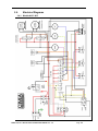
1
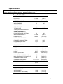
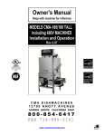
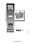
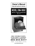
Owner’s Manual Keep with machine for reference MODELS AH/B/C/Scullery/Pizza/Bowl INSTALLATION & OPERATION Rev 1.01 CMA DISHMACHINES 12700 KNOTT STREET GARDEN GROVE, CALIFORNIA 92841 800-854-6417 FAX 714-895-2141 www.cmadishmachines.com TABLE OF CONTENTS MODEL AH/B/C/S. 1. SPECIFICATIONS ........................................................................................ 3 1.1 MODEL AH/C ...................................................................................................................................... 3 1.2 MODELS B/B ENERGY SAVER ............................................................................................................. 4 1.3 AH, B AND C OPERATIONAL CYCLE.................................................................................................... 5 2. GETTING STARTED ..................................................................................... 7 2.1. INTRODUCTION TO MODELS AH, B ,C&” S” SERIES. ........................................................................... 7 2.2. RECEIVING AND INSTALLATION........................................................................................................... 8 3. 2.2.1. Electrical .................................................................................................................................... 8 2.2.2. Plumbing ..................................................................................................................................... 8 2.2.3. Connecting the Scrap Accumulator and Drain ........................................................................... 9 2.2.4. Installer’s Checklist .................................................................................................................. 10 OPERATION ............................................................................................... 11 3.1. INITIAL SETUP ................................................................................................................................... 11 3.1.1. Check… ..................................................................................................................................... 11 3.1.2. Filling the Machine................................................................................................................... 11 3.1.3. Chemicals ................................................................................................................................. 11 3.1.4. Run a Cycle ............................................................................................................................... 11 3.2. GENERAL ........................................................................................................................................... 12 3.3. ADDENDUM FOR MACHINES INSTALLED IN THE CITY OFCHICAGO .................................................... 13 3.4. ELECTRICAL DIAGRAMS .................................................................................................................... 14 3.4.1. Models AH/ C & B .................................................................................................................... 14 3.4.2. Solid Bowl ................................................................................................................................. 15 1. Specifications Electrical and plumbing connections must be made by a qualified service person who will comply with all available Federal, State, and Local Health, Electrical, Plumbing and Safety codes 1.1 Model AH/C USA METRIC PER RACK 1.7 GAL. (6.45 L) PER HOUR 74 GPH (280.1 LPH) WASH TIME-SEC. 45 45 RINSE TIME-SEC. 30 30 DWELL TIME-SEC. 15 15 90 SEC.* 90 SEC.* 40 40 WATER CONSUMPTION OPERATING CYCLE TOTAL CYCLE *Other cycle times are available OPERATING CAPACITY RACKS PER HOUR (NSF Rated) WASH TANK CAPACITY 1.7 GAL. (6.45 L) PUMP CAPACITY 52 GPM (197 LPM) REQUIRED MINIMUM TEMP. 120°F (49°C) RECOMMENDED TEMP. 140°F (60°C) WATER INLET ¾” 1.9cm DRAIN CONNECTION 2” 5.1cm DEPTH 25 ¾” (65.4cm) WIDTH 25 ¾” (65.4 cm) WATER REQUIREMENTS DIMENSIONS HEIGHT 56-57” (142-144.8cm) 66”-67” (168-170 cm) MAX CLEARANCE FOR DISHES 17” (43.18 cm) MAX CLEARANCE FOR DISHES (S) 27” (68,58”cm) STANDARD TABLE HEIGHT 34” (86.36 cm) 19 ¾” x 19 ¾” (50 x 50 cm) VOLTS (60-Hz) AMPS 115 16 HEIGHT (SCULLERY) STANDARD DISH RACKS ELECTRICAL RATING WASH PUMP MOTOR 1 HP SHIPPING WEIGHT APPROXIMATE 270# (122.5 kg) APPROXIMATE (SCULLERY) 295# (133.8 kg) MODEL AH, B & C INSTALLATION & OPERATION MANUAL Rev. 1.01 Page 3 Electrical and plumbing connections must be made by a qualified service person who will comply with all available Federal, State, and Local Health, Electrical, Plumbing and Safety codes 1.2 Models B/B Energy Saver USA METRIC WATER CONSUMPTION PER RACK 1.5/ .96 GAL. (5.7/ 3.63 L) PER HOUR 118.4/ 76.8 GPH (448/291 LPH) 45 45 OPERATING CYCLE WASH TIME-SEC. RINSE TIME-SEC. 30 30 DWELL TIME-SEC. 15 15 90 SEC.* 90 SEC.* 80 80 WASH TANK CAPACITY 3.0 GAL. (11.4 L) PUMP CAPACITY (two pumps) 104 GPM (393.68 LPM) REQUIRED MINIMUM TEMP. 120°F (49°C) RECOMMENDED TEMP. 140°F (60°C) WATER INLET ¾” 1.9cm DRAIN CONNECTION 2” 5.1cm DEPTH 25 ¼” (64 cm) WIDTH 44 ¼” (112 cm) TOTAL CYCLE *Other cycle times are available OPERATING CAPACITY RACKS PER HOUR (NSF Rated) WATER REQUIREMENTS DIMENSIONS HEIGHT HEIGHT (SCULLERY) 55 ½”-56 ½” (141-143.5 cm) 65-66” (165-168cm) MAX CLEARANCE FOR DISHES 17” (43.18 cm) MAX CLEARANCE FOR DISHES (S) 27" (68,58cm) STANDARD TABLE HEIGHT 34” (86.36 cm) 19 ¾” x 19 ¾” (50 x 50 cm) VOLTS (60-Hz) AMPS 115 30 STANDARD DISH RACKS ELECTRICAL RATING WASH PUMP MOTORS (2) 1 HP each SHIPPING WEIGHT APPROXIMATE 352# (160 kg) APPROXIMATE (SCULLERY) 377# (171 kg) Note: The required flowing water pressure to the dishwasher is 15-65 PSIG. If pressures higher than 65 PSIG are present, a pressure regulating valve must be installed in the water line to the dishwasher (by others). If flowing pressure is lower than 15 psi, improper machine operation may result. MODEL AH, B & C INSTALLATION & OPERATION MANUAL Rev. 1.01 Page 4 AH, B and C Operational Cycle* 1.3 The AH, B and C Operational Cycle have a total cycle time of 90 seconds. The Timing Diagram and the steps listed below detail the individual functions that are executed during each Operational Cycle. Seconds: 0 10 20 30 40 50 60 70 80 90 Cam 1 Start/Stop Cam 2 Cycle Reset Cam 3 WASH DRAIN RINSE Drain/Rack Counter Cam 4 Flush/Fill Cam 5 Detergent Cam 6 Sanitizer Cam 7 Rinse Aid Cam 8 Pump Motor 1. With the machine powered up, closing the doors begins a cycle. 4sec. delay to prevent chemical damage a) When the door closes the timer assembly motor is energized through the normally closed contact of the Start/Stop Relay. b) Within a couple of seconds cams 1 and 2 close their respective switches. Cam switch 1 (Start/Stop) maintains power to the timer assembly motor throughout the 90-second cycle. Cam switch 2 (Cycle Reset) energizes the Start/Stop Relay. c) The Start/Stop Relay, once it is energized by cam switch 2, is held in by its own normally open contact for as long as the doors remain closed. 2. Cam switch 8 controls the pump motor. The pump motor comes ON at the beginning of the operational cycle and continues to run until the end of the drain function (controlled by cam switch 3), at which time it turns off for about eight seconds allowing time for the machine to refill enough to avoid running the pump dry before the pump motor restarts and runs to the completion of the operational cycle. * “S” series same otherwise noted MODEL AH, B & C INSTALLATION & OPERATION MANUAL Rev. 1.01 Page 5 The pump motor runs the pump for the 45-second wash cycle, then pumps the water out through the drain, turns off for about 8 seconds (allowing the machine to refill with clean rinse water) and then runs the pump for the 30-second rinse cycle. 3. Cam switch 3 controls the drain function. At the end of the 45-second wash cycle, cam switch 3 energizes the drain solenoid allowing the wash water out of the machine. Cam switch 3 also increments the rack counter by one each cycle. 4. Cam switch 4 controls the water solenoid valve on the water supply to flush and fill the machine. At the end of the wash cycle the drain solenoid valve is open and drain begins, the pump motor continues to run. About the middle of the drain cycle, Cam 4 opens the fill solenoid valve and the flush function begins flushing residual detergent. At the end of drain cycle, drain solenoid valve closes and the pump motor is stopped— the machine begins to fill for the rinse cycle. Once the machine has refilled sufficiently, the pump motor restarts carrying out the rinse portion of the cycle as the filling of the wash tank completes. This can be adjusted as necessary for water pressure situation. 5. Cam switch 5 controls the detergent pump and turns ON about 5 seconds after the operational cycle is started and runs for a few seconds to provide sufficient detergent for the wash cycle. This cam can be adjusted as necessary for proper detergent dosage. 6. Cam switches 6 and 7 control the sanitizer and rinse pumps respectively. They turn ON at the beginning of the rinse cycle and run for a few seconds to provide sufficient sanitizer and rinse aid for the rinse cycle. These cams can be adjusted as necessary for proper chemical dosage. 7. At the end of the cycle cam switches 1 and 2 open (de-energize) stopping the cycle. The Start/Stop relay is held energized by its normally open contact until the doors are opened. Opening the doors de-energizes the Start/Stop Relay, which will then cause a new cycle to start when the doors are once again closed. Note: Holding the START switch on for a couple of seconds will start a cycle without opening and closing the doors. MODEL AH, B & C INSTALLATION & OPERATION MANUAL Rev. 1.01 Page 6 2. Getting Started All sections of the manual address dishmachine models AH, B ,C & “S”series. Separate information on each machine is only provided where differences exist between the models. 2.1. Introduction to Models AH, B ,C&” S” series. The CMA AH, B ,C &”S”series.Dishmachines are safe and easy to operate with their “Auto Start/Stop” function. The Dishmachines’ top mounted controls include built-in chemical pumps controlled by adjustable cams to insure proper chemical usage. The integrated scrap accumulator prevents food soil from entering the drain system. The models AH and C can be run at a rate of 40 racks/160 covers per hour, while the model B can be run at a rate of 80racks/320 covers per hour and their heavy-duty stainless steel construction assures long life and years of trouble free operation. There are also accessories that can be chosen when desired such as the optional Sani Alarm, Solid Bowl, dish tables,temp sure booster heater. The supply water to the dishmachine should be 140°F. The pipe supplying the water must be ¾” minimum. The supply water connects to the gate valve located at the back of the machine (¾” female pipe thread connection). The drain is 2" and comes off of the scrap accumulator for easy attachment of your drain line. See section 2.2.3 Connecting the Scrap Accumulator and Drain. This manual is structured to provide a complete reference guide to the models AH,B,C &”S” series Dishmachines. It is presented in a manner that all users will be able to comprehend and use as an effective tool in supporting the operation and maintenance of the dishmachine. The first section explains how the machine is packaged and what to look for when receiving the machine. After unpacking the machine, this manual explains how to install and set up the machine for use. Requirements are given for plumbing, wiring, and space considerations. These attributes of the machine are always taken into consideration by our well-trained sales representatives prior to the order being placed. In the manual, guidance is also given for installation to ensure that the machine will be able to run at optimum conditions. The Operation section of the manual may be used for instruction and procedures when required. This section also includes electrical diagrams for the Dishmachines. This portion of the manual is made easy to understand so that all levels of operators may be able to read and comprehend the operation of the machine. The function of the machine itself is mostly automatic and takes little training to put into full operation. There is also an addendum for machines installed in the city of Chicago. CMA warranties the workmanship of the machine. At CMA we are committed to providing the best machines and customer service in the food industry and your feedback is welcome. DISCLAIMER OF LIABILITY OF WARRANTY: CMA EXPRESSLY DISCLAIMS ANY AND ALL WARRANTIES, EXPRESS OR IMPLIED, RELATING TO THE INSTALLATION OF ANY AND ALL CMA EQUIPMENT THAT IS INSTALLED BY CHEMICAL DEALERS, CONTRACTED SERVICERS OR THIRD PARTY SERVICERS TO CMA EQUIPMENT. IF THE INSTALLATION INSTRUCTIONS ARE NOT FOLLOWED EXACTLY (TO THE LETTER), OR, IF ANY PERSON OR COMPANY CONDUCTING THE INSTALLATION OF THE CMA EQUIPMENT, REVISE THE INSTALLATION PROCEDURES OR ALTER THE INSTRUCTIONS IN ANY MANNER, THE CMA WARRANTY BECOMES VOID. IF, DUE TO THE IMPROPER INSTALLATION OF CMA EQUIPMENT, THIS EQUIPMENT CEASES TO OPERATE PROPERLY OR AFFECTS OTHER PARTS OF THE CMA DISHWASHING EQUIPMENT, IN THAT THE OTHER PARTS BECOME DEFECTIVE, THE CMA WARRANTY BECOMES VOID. CMA WILL NOT BE LIABLE OR RESPONSIBLE OR WARRANT CMA EQUIPMENT, DUE TO IMPROPER INSTALLATION OF ANY CMA MODEL DISHWASHER. MODEL AH, B & C INSTALLATION & OPERATION MANUAL Rev. 1.01 Page 7 Getting Started 2.2. Receiving and Installation The dishwasher is shipped from the factory in a corrugated box on a wooden pallet. The installation guidelines give a systematic procedure for setting up the machine. Start by removing the dishmachine from the box. Remove the packaging, unwrap the machine and check for the following components: Scrap Accumulator complete with lid and scrap tray. Inside the wash tank is a box with one control box key, 4 legs, thermometer, spray arms, machine manual and a cam timer wrench. Tube Stiffeners: The tube stiffeners must be used to prevent the feed tubes from curling up inside the chemical pail allowing the tip to rise out of the chemical. Remove the tie-wraps securing the tube stiffeners to the dishmachine to free them up for use. Be careful not to remove any of the tie-wraps securing the tube bundle. Red is for detergent, white for sanitizer, and blue for rinse aid. 2.2.1. Electrical * Prior to installation make sure the electrical supply is compatible with the specifications on the machines data plate. 115 volt, 60 Hz dedicated circuit must be used to supply electrical power to the models AH, B, C and S Dishmachines (see model AH specifications on page 3, model B specifications on page 4, model C specifications on page 5). WARNING: Electrical and grounding connections must comply with the applicable portions of the National Electrical Code and/or other local electrical codes. Note: For supply connections, use copper wire only rated at 90 degree C minimum. 2.2.2. Plumbing* The water supply connection is made with a ¾” hot water line to the water supply inlet on the top of the machine. The water supplied to the machine is recommended to be 140° F (120° F minimum). Caution: Do not connect galvanized pipe water supply to dishmachine. This will create electrolysis, causing corrosion. Notice to Plumber: The plumber connecting this machine is responsible for making certain that the water lines are THOROUGHLY FLUSHED OUT BEFORE connecting to the dishwasher. * Electrical and plumbing connections must be made by a qualified service person who will comply with all available Federal, State, and Local Health, Electrical, Plumbing and Safety codes MODEL AH, B & C INSTALLATION & OPERATION MANUAL Rev. 1.01 Page 8 Getting Started Ask your municipal water supplier for details about your local water conditions prior to installation. Recommended water hardness is 3 grains per gallon or less. Note: high iron levels in the water supply can cause staining and may require an iron filter. High chlorine levels in the water supply can cause pitting and may require a chloride removal system. If an inspection of the dishwasher or booster heater reveals lime buildup after the equipment has been in service, water treatment is recommended. If water softener is already in place, ensure there is a sufficient level of salt. Technical personnel are available during normal business hours at CMA Headquarters should you, as an installer, have any questions please call 800-854-6417. 2.2.3. Connecting the Scrap Accumulator and Drain The scrap accumulator is designed to perform two basic functions: 1. It allows all the heavy solids to discharge out of the machine with each wash cycle and collect in a clean out tray. 2. It provides accumulation capacity to allow draining the contents of one cycle regardless of the discharge rate of the existing drain. The drain pipe is connected to the scrap accumulator drain using a 2” no-hub connector (not supplied) as shown in Figure 2.2.3 below. Figure 2.2.3 MODEL AH, B & C INSTALLATION & OPERATION MANUAL Rev. 1.01 Page 9 Getting Started 2.2.4. Installer’s Checklist Dishmachine checked for concealed damage Hot water supply is minimum 120°F, recommended 140° F (49/60 C) Incoming water supply line is ¾” minimum (not galvanized) Supply circuit breaker for machine is properly sized Service voltage and phase type are correct to machine data plate Drain pipe is installed with adequate air gap (must meet local codes) Dishmachine is properly grounded Dishmachine is properly leveled Machine circuit breaker is labeled “DISHWASHER” Machine has been connected with correctly sized wire MODEL AH, B & C INSTALLATION & OPERATION MANUAL Rev. 1.01 Page 10 3. Operation 3.1. Initial Setup All machines are equipped with switches to prime the peristaltic pumps at anytime the master switch is "ON". Following completion of the installation, always fill the machine with water before starting it. Caution: Do not operate the dishmachine without the drain screen in place. Debris getting into the pump impeller can damage the pump. 3.1.1. Check… Drain screen is in place Spray arms and end plugs are secure 3.1.2. Filling the Machine With the power “ON” hold the fill button until the water level is approximately ½” to ¾” below the overflow hole in the PVC standpipe. The water level should be approximately even with the bottom edge of the splash guard in the sump area of the machine. 3.1.3. Chemicals • Assure there is a sufficient supply of chemicals before beginning a shift. • Check the chemical lines to the chemical containers. a. Red: detergent line. b. Blue: rinse agent line. c. Clear/White: sanitizer line. • Activate the prime switches for the three chemical pumps until product is discharging into the machine. Note: Use only commercial-grade detergents and rinse aids recommended by your chemical professional. Do not use detergents and rinse aids formulated for residential dishwashers. Low Temperatures chemical-sanitizing dishmachines must not exceed 6% sodium hypochlorite solution (bleach) as the sanitizing agent. Higher levels may damage stainless or components. Follow the directions precisely that are on the litmus paper vial and test the water on the surface of the bottom of the glasses. Concentration should be 50 p.p.m. minimum to 100 p.p.m. maximum. If concentration is incorrect contact your chemical supplier. 3.1.4. Run a Cycle To start the machine close the doors - the machine will automatically start and run through its cycle. Watch to ensure that the chemicals are delivered and stop during the cycle. The amount of chemical delivered, whether it is detergent, sanitizer or rinse aid, is determined by its respective cam on the cam timer. • Cam number 5 runs the detergent pump • Cam number 6 runs the sanitizer pump • Cam number 7 runs the rinse aid pump These cams were set at the factory but can be adjusted after final installation to maximize efficiency of chemical use .Check the water temperature at the end of the cycle for minimum 120°F, recommended 140°F (49/60°C). MODEL AH, B & C INSTALLATION & OPERATION MANUAL Rev. 1.01 Page 11 Operation CAUTION: Excessive tightening of the cover plate screws may stall the motors on the new peristaltic pumps. If a peristaltic pump does not turn when the micro switch is activated, loosen the screws on the cover plate. 3.2. General Please follow the instructions given here before each shift to assure trouble free operation. Caution: Do not operate the dishmachine without the drain screen in place. Debris getting into the pump impeller can damage the pump. 1. Drain the water if it is cold by lifting the drain ball until all the water is out of the machine. 2. Check the drain screen and, if needed, remove it from the machine and clean it out. After cleaning, replace it properly into the sump housing. 3. Check the wash arm spray tips. If they are clogged, clean them with a toothpick and rinse them at the sink. Replace the wash arms. 4. Check the chemical lines to the chemical containers. a. Red: detergent line. b. Blue: rinse agent line. c. Clear/White: sanitizers destainer line. 5. Press and hold the fill switch until the water level is approximately ½” to ¾” below the overflow hole in the PVC standpipe. The water level should be approximately even with the bottom edge of the splash guard in the sump area of the machine. 6. Once a proper water level is established, check the temperature of the water (it should be minimum 120°F, recommended 140°F, 49/60°C). 7. Insert a rack of dishes into the machine and close the doors. The machine will automatically start when the doors are closed. 8. After the machine stops, raise the doors, remove the rack of dishes (allow to dry before stacking). 9. Insert the next rack of dishes into the machine and close the doors. Again the machine will automatically start when the doors are closed. 10. At the end of the shift, drain the machine by lifting the drain ball out of the drain until the machine is completely drained. 11. Remove and clean the drain screen. Remove and clean the spray arms. (See wall chart instructions). 12. Replace the drain screen and spray arms. If the doors are lifted during a cycle, the machine will automatically stop running. The machine will run through the wash and rinse cycles automatically feeding the proper chemicals and then turn itself off. In an emergency you can turn off the machine by turning off the main power switch at the back of the control box. Note: It is essential that the operator thoroughly understand the importance of pre-scrapping the dishes before loading them. All Dishmachines are equipped with a removable drain screen. The drain screen can be easily removed for cleaning between Operational Cycles of the dishmachine. Properly prescrapping the dishes should permit the dishmachine to operate for an entire shift before needing to remove and clean the drain screen. MODEL AH, B & C INSTALLATION & OPERATION MANUAL Rev. 1.01 Page 12 Operation 3.3. Addendum for Machines Installed in the City ofChicago "All food dispensing establishments using chlorine or other approved chemical sanitizers shall, at all times, maintain an adequate testing device." "Dishes and other eating and drinking utensils to be washed in a dishwashing machine shall be properly scraped and pre-rinsed and shall be stacked in racks or trays so as to avoid overcrowding, and so as to permit the wash and rinse waters to reach all surfaces of each utensil." "In machine washing, multi-use eating and drinking utensils shall be washed in water containing a suitable detergent at a temperature minimum 120 degrees F,recommended 140 degrees F. or other method approved by the Department of Health. "The water in the wash tank shall be changed during operation as often as is necessary to keep it reasonably clean. An effective concentration of detergent in the wash water shall be maintained at all times." "Bactericidal treatment shall consist of exposure of all surfaces of dishes and utensils being washed to a rinse of clean water, at a temperature of not less than 180 degrees F. or other method approved by the Department of Health." "All dishwashing machines shall maintain a flow pressure not less than 15 or more than 25 pounds per square inch on the fresh water line at the machine and not less than 10 pounds per square inch at the rinse nozzles. A suitable gauge cock shall be provided immediately upstream from the final rinse spray to permit checking the flow of the final rinse water. An easily readable thermometer accurate to ± 2 degrees F. shall be provided on both the wash and rinse water lines of the dishwashing machine which will indicate the temperature of the water solution therein." "Dishwashing machines shall be thoroughly cleaned at least once each day. The pumps and the wash and rinse sprays or jets shall be so designed that a forceful stream of water will reach all surfaces of the utensils when they are properly racked. These parts shall be thoroughly cleaned at least once each day. The pumps and the wash and rinse sprays or jets shall be so designed that a forceful stream of water will reach all surfaces of the utensils when they are properly racked. These parts shall be readily accessible for inspection and cleaning." "After bactericidal treatment, utensils and containers shall be stored at a sufficient height above the floor in a clean, dry place, protected from flies, splash, dust, overhead leakage and condensation, and other contamination. Containers and utensils shall be inverted, covered, or otherwise protected from contamination until used for serving." Drain racks, trays, and shelves shall be made of non-corrodible material and shall be kept clean. In handling containers and utensils the surfaces thereof which come in contact with food or drink shall not be touched by the hands, except during the process of washing. Tables for clean and dirty dishes and food shall be so arranged that the dirty dishes will be as far removed from the food and clean dishes as may be possible. All single-service articles and utensils shall be purchased in sanitary cartons and stored therein in a clean, dry place until used, and after removal from the cartons, these articles shall be handled in such a manner as to prevent contamination. Please note the following procedures must be followed for City of Chicago Approval: 1. All low energy models must have low level sani-alarms, both visual and audio. 2. All models must have a City of Chicago approval data label affixed to the machine. 3. Chlorine sanitizer must be a minimum of 100 PPM. MODEL AH, B & C INSTALLATION & OPERATION MANUAL Rev. 1.01 Page 13 3.4. Electrical Diagrams 3.4.1. Models AH/ C & B MODEL AH, B & C INSTALLATION & OPERATION MANUAL Rev. 1.01 Page 14 3.4.2. Solid Bowl MODEL AH, B & C INSTALLATION & OPERATION MANUAL Rev. 1.01 Page 15