1
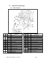
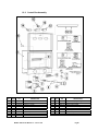
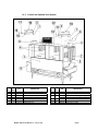
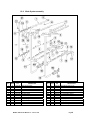
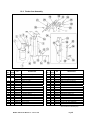
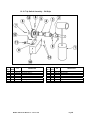
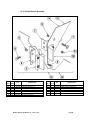
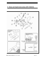
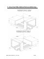
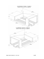
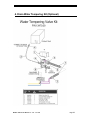
MODEL CMA-66
PARTS MANUAL
Rev 1.06A
CMA DISHMACHINES
12700 KNOTT AVENUE
GARDEN GROVE, CALIFORNIA 92841
800-854-6417
FAX 714-895-2141
www.cmadishmachines.com
Table of Contents
CMA-66
1.
PARTS MANUAL...................................................................................................... 4
1.1.
Initial Parts Kit (P/N 13996.80)...................................................................................................... 4
1.2.
Exploded View Drawings............................................................................................................... 5
1.2.1.
1.2.2.
1.2.3.
1.2.4.
1.2.5.
1.2.6.
1.2.7.
1.2.8.
1.2.9.
1.2.10.
1.2.11.
1.2.12.
Cabinet Assembly ................................................................................................................... 5
Control Box Assembly ............................................................................................................ 6
Curtain and Optional Vent System ......................................................................................... 7
Temperature Control System .................................................................................................. 8
Pump Assembly....................................................................................................................... 9
Drain System Assembly......................................................................................................... 10
Plumbing System Assembly................................................................................................... 11
Wash System assembly.......................................................................................................... 12
Rocker Arm Assembly ........................................................................................................... 13
Trip Switch Assembly – Old Style ......................................................................................... 14
Trip Switch Assembly – New Style........................................................................................ 15
Paddle Switch Assembly ....................................................................................................... 16
2.
TABLE LIMIT SWITCH INSTRUCTIONS (P/N 13469.20).......................... 17
3.
CORNER FEED TABLE (OPTIONAL FACTORY INSTALLED ONLY)... 19
4.
DRAIN WATER TEMPERING KIT (OPTIONAL) ........................................ 21
www.cmadishmachines.com
Parts Manual
1. Parts Manual
1.1.
Initial Parts Kit (P/N 13996.80)
P/N
DESCRIPTION
Qty
00201.85
Pump Motor, 1HP, 3Ph, 60 Hz, 220V
1
00206.00
Pump Seal Kit
1
00208.00
Slip Joint Nut Gasket
1
00411.00
Micro Switch
1
00421.83
CMA-66 Power Rocker Switch, Red
1
00421.87
CMA-66Heater Rocker Switch, White
1
00557.30
Kynar Reed Switch Gray, 110/220V, 12’
1
00557.56
Kynar Reed Switch Black, 110/220V, 12’
1
00707.00
½” Water Solenoid Repair Kit JE
1
00738.15
¾” & ½” Solenoid Coil JE 220V
1
03202.00
Thermometer (Capillary)
1
03226.00
Pump O-Ring Gasket
1
03623.00
½ Vac Breaker Repair Kit Watts
1
13003.50
Contactor, 30-Amp
1
13003.70
Toggle Switch SPDT 20AMP
1
13012.26
CMA-66P Motor Contactor, 220V
1
13403.26
Fuse, 3-Amp/250V Slow Blow
2
13417.80
Immersion Heater, 3Ph/1Ph, 208-230V, 10kW
1
13418.85
60-Second Timer Relay
1
13463.10
Liquid Level Switch, SS – CMA-66
1
13501.85
Motor 1/3Hp 200-230/460 60hz 3ph
1
13507.50
Cam Bearing, SS
1
13508.60
Swivel Hook Spring Assembly
1
MODEL CMA-66 Part Manual rev. 1.06
01/11/05
Page 4
1.2.
Exploded View Drawings
1.2.1. Cabinet Assembly
ITEM NO.
NO. REQ’D
1
2
1
1
3
1
4
5
6
7
8
9
10
11
12
13
14
15
16
2
2
4
4
4
2
26
60
54
2
8
1
1
17
1
P/N
13903.36
13902.35
13902.45
13900.36
13900.46
01506.30
13901.00
01554.30
00636.10
13915.00
00535.30
00905.00
00924.00
00912.00
13906.36
00914.10
13511.26
13511.06
13511.16
DESCRIPTION
ITEM NO.
NO. REQ’D
Frame Stand
L-R Pan
R-L Pan
L-R Wrapper
R-L Wrapper
Door
Wrapper Shield
Door Guide
Door Guide Plastic
Door Latch Bracket
Door Handle
1/4-20 x 1/2” Trusshead Bolt
1/4” Washer, SS
1/4-20 Nylon Lock Nut
Tray Track Rail
1/4-20 x 5/8” Hex Head Bolt
Overflow Chute Gasket
L-R Overflow Chute
R-L Overflow Chute
18
19
20
21
22
23
24
25
26
27
28
29
30
31
32
33
3
1
1
8Ft
2
1
1
2
1
1
1
1
2
2
2
1
34
35
13927.06
L-R Heater Cover
36
13927.16
R-L Heater Cover
MODEL CMA-66 Part Manual rev. 1.05 01/11/05
P/N
DESCRIPTION
1
2
13910.82
13913.00
13542.00
03705.00
13010.06
13504.26
13504.06
13701.00
01577.10
17579.00
01577.20
13912.36
00557.60
00557.30
13912.81
13704.08
13704.06
13522.06
00962.00
Strainer Basket, Wash/Rinse
Drip Chute
Drip Chute Gasket
Foam Tape
Drain Valve Handle Support
Gearbox Cover Mount (Optional)
Gearbox Cover (Optional)
Door Latch
Scrap Trap Body molded
Scrap Trap Holder
Scrap Trap Drawer molded
Splash Shield
Reed Switch Magnet
Kynar Reed Switch only 110/120
Splash Shield Clip
L-R Curtain Splash Shield
R-L Curtain Splash Shield
Conveyor bar guide
¼’-20x1” Hexhead Bolt
1
01577.36
Scrap Trap Cover SS
Page5
1.2.2. Control Box Assembly
ITEM NO.
NO. REQ’D
1
2
3
4
5
6
7
8
9
1
4
2
2
2
1
1
1
1
P/N
13904.06
13012.26
13003.50
03202.00
03202.08
00454.06
13003.70
00470.10
13003.60
DESCRIPTION
Control Box w/Lid
Motor Contactor, 220V
Contactor, 30-Amp
Thermometer
Thermometer Bracket
6-Pole Terminal Block
Timer Relay Override Switch
Toggle Switch Rubber Boot
Starter DIN Rail
MODEL CMA-66 Part Manual rev. 1.05 01/11/05
ITEM NO.
NO. REQ’D
10
11
12
13
14
15
16
17
2
2
1
1
1
1
2
1
P/N
DESCRIPTION
17503.17
17503.18
00421.87
00421.26
00421.83
00449.50
13403.26
13013.30
Control Box Sponge, Long
Control Box Sponge, Short
Rocker Switch, White
Rocker Switch Hole Plug
Power Rocker Switch, Red
Lock, Keyless
Fuse, 3-Amp/250V Slow Blow
1/3 HP Overload Relay 1.2amp-1.8Amp
Page6
1.2.3. Curtain and Optional Vent System
ITEM NO.
NO. REQ’D
1
2
3
4
5
6
7
1
2
1
4
2
3
4
P/N
13912.82
13702.25
13702.15
13702.30
13704.26
13705.00
13705.10
DESCRIPTION
Splash Shield
Curtain, 20-5/8” x 15”
Curtain, 20-5/8” x 11”
Curtain, 24-5/8” x 15”
Double Curtain Splash Guard Bracket
Curtain Rod, Short
Curtain Rod, Long
MODEL CMA-66 Part Manual rev. 1.05 01/11/05
ITEM NO.
NO. REQ’D
8
9
10
1
1
2
11
12
13
2
4
4
P/N
13901.82
13932.06
13704.16
13704.36
13704.46
00907.00
00965.00
DESCRIPTION
(Optional) Hood Adapter – set of 2
(Optional) Conveyor Motor Cover Kit
Dual Curtain Holder (Right to Left)
Dual Curtain Holder (Left to Right)
Dual Curtain Rod Stop
6-32 x 1/2" Pan Head Screw
6-32 Nylon Lock Nut
Page7
1.2.4. Temperature Control System
ITEM NO.
NO. REQ’D
P/N
DESCRIPTION
1
1
13417.80 Immersion Heater, 3Ph, 240V, 10kW*
2
1
13463.10 Liquid Level Switch, SS
3
1
13417.89 Thermostat 12KW Heater
4
1
03202.00 Thermometer
5
1
13463.50 Liquid Level Switch Shield
* Includes P/N 13417.89 Thermostat w/c can be ordered separately
MODEL CMA-66 Part Manual rev. 1.05 01/11/05
ITEM NO.
NO. REQ’D
6
7
8
9
10
1
1
4
4
8
P/N
13416.10
13417.45
00901.00
13805.00
00926.00
DESCRIPTION
Thermostat Bracket
Heater Gasket
5/16 – 18 x 1” Hexhead Bolt
5/16 – 18 Nylon Nut
5/16” SS washer
Page8
1.2.5. Pump Assembly
ITEM NO.
NO. REQ’D
1
2
3
4
5
6
7
8
9
10
11
2
2
2
2
2
2
2
2
2
4
4
P/N
DESCRIPTION
00201.85
03224.00
00206.00
03226.00
03222.85
04206.00
00208.00
04204.00
13916.00
00906.00
00922.00
Pump Motor, 1HP, 3Ph, 60 Hz, 220V
Pump Base Mount
Pump Seal Kit
Pump O-Ring Gasket
CMA-66 Water Pump Impeller
Pump Cover
Slip Joint Nut Gasket
Compression Nut, 2.5”
Motor Support Bracket
1/4-20 x 1/2” Hex Bolt
1/4” Lock Star Washer
MODEL CMA-66 Part Manual rev. 1.05 01/11/05
ITEM NO.
NO. REQ’D
12
13
14
15
16
17
18
19
20
21
4
4
16
2
4
2
2
1
2
2
P/N
DESCRIPTION
00924.00
00912.00
00921.00
13829.00
00238.00
00213.00
00225.00
00704.85
00200.85
00208.20
1/4” SS Washer
1/4-20 Nylon Lock Nut
3/8-16 x 3/4” SS Hex Head Bolt
7/16-20 Thin Nylon Lock Nut
3/8” Male Plug
1” Ford Adapter, MIP x PJ Tube
1” Compression Gasket
1”, 90° Elbow*
Motor Assembly, 1HP, 3Ph, 220V, 60 Hz**
Slip Joint Nut Friction Ring
*For CMA-66 R-L only.
**Includes Items 1, 2, 3, 4, 5 and 14.
Page9
1.2.6. Drain System Assembly
ITEM NO.
NO. REQ’D
1
2
3
4
5
1
2
2
2
2
P/N
13001.85
20500.06
01317.17
03001.82
50109.00
DESCRIPTION
Drain Manifold
Waste Drain Valve
1-1/2” x 2” No Hub
Drain Pipe Support Bracket
Hose Clamp
MODEL CMA-66 Part Manual rev. 1.05 01/11/05
ITEM NO.
NO. REQ’D
6
7
8
9
2
4
1
2
P/N
00912.00
00924.00
13024.00
00906.0
DESCRIPTION
1/4-20 Lock Nut
1/4“ Washer, SS
Dynamite Plug, 2”
1/4-20 x 1/2” Hex Head Bolt
Page10
1.2.7. Plumbing System Assembly
ITEM NO.
NO. REQ’D
1
2
3
4
5
6
7
7A
7B
8
9
10
11
12
13
14
15
16
1
1
1
1
4
2
1
1
1
1
1
1
1
1
1
1
2
1
P/N
03603.15
00738.15
03603.20
00707.00
03614.00
41030.10
03624.00
03623.00
03624.25
00716.00
13602.45
03202.00
13604.00
13605.00
13028.00
00743.10
01525.06
13610.30
DESCRIPTION
1/2” Water Solenoid Valve 220V, JE*
Water Solenoid Valve Coil, 220V, ½” & ¾”
1/2” Water Solenoid Valve Bonnet
1/2” Water Solenoid Valve Repair Kit
1/2” Close Nipple, Brass
1/2” 90° Elbow, F x F, Brass
1/2” Vacuum Breaker, Watts**
1/2” Vacuum Breaker Repair Kit
1/2” Vacuum Breaker Bonnet
1/2” x 1/2” x 3/4” F x F x F Tee, Brass
1/2” Pressure Regulator
Thermometer (Capillary)
1/2” x 1/4” Bushing
Pressure Gauge
3/4” Ball Valve, 3-piece
1/2” Tee, F x F x F
Plumbing Support Bracket
1/2” Union, SS
*Includes Items 2, 3 and 4.
**Includes Items 7A, 7B, 25C and 25D.
MODEL CMA-66 Part Manual rev. 1.05 01/11/05
ITEM NO.
NO. REQ’D
17
18
19
20
21
22
23
24
25
25A
25B
25C
25D
26
27
28
29
30
1
1
2
2
1
3
1
1
1
1
1
2
4
2
1
1
1
1
P/N
00747.30
13669.60
03232.00
13606.00
13612.00
00704.00
13634.06
13633.00
00710.50
00735.00
00735.60
00739.50
00421.51
00742.00
00781.00
00749.00
00786.00
00780.00
DESCRIPTION
1/2” x 3” SS Nipple
Mixing Chamber, 1/2” SS
1/8” Male Plug
3/4” Jamb Nut, Brass
3/4” x 5” Brass Nipple
3/4” 90° Street Elbow
3/4” x 8” Nipple, Brass
3/4” 90° Elbow, F x F, Brass
3/4” Vacuum Breaker***
3/4” Vacuum Breaker Repair Kit
3/4” Vacuum Breaker Bonnet
Vacuum Breaker Cap
6-32 x 1/4” SS Panhead Screw
1/2” x 2” Nipple, Brass
3/4” x 3-1/2” Nipple, Brass
Coupling 3/4” Brass
Water Solenoid Plunger with Spring
Nipple, Brass, 1/2” x 2-1/2”
***Includes Items 25A, 25B, 25C and 25D.
Page11
1.2.8. Wash System assembly
ITEM NO.
NO. REQ’D
1
2
3
4
5
6
7
7A
8
9
10
11
6
2
2
6
6
2
2
8
2
4
3
1
P/N
13305.06
13327.06
13327.26
13303.06
04306.10
13310.00
13304.30
13304.56
13618.00
00721.20
13629.00
13630.00
DESCRIPTION
Spray Arm End Cap
Socket Bracket, Double
Socket Bracket, Single
Spay Arm
Square Manifold Gasket
1/2” Cap, Brass
Final Rinse Spay Arm*
Final Rinse Spray Jets, SS
1/2” Coupling
1/2" Jamb Nut, Brass
1/2" Close Nipple, SS
1/2”F x F x F Tee, SS
*Includes Item 7A
MODEL CMA-66 Part Manual rev. 1.05 01/11/05
ITEM NO.
NO. REQ’D
12
13
14
15
16
16A
17
18
19
20
21
22
1
1
1
1
2
2
32
64
32
1
1
2
P/N
13307.00
13628.00
13301.26
13301.06
00213.00
00225.00
13305.40
00924.00
00912.00
13304.53
13669.60
03232.00
DESCRIPTION
Final Rinse Tube, 23-1/2”
1/2" 90° Elbow, F x F, SS
Wash Manifold
Pre-wash Manifold
1” Ford Adapter, MIP x PJ Tube**
1” Compression Gasket
Shoulder Bolt
1/4" SS Washer
1/4-20 Nylon Lock Nut
Long Support Bracket
Mixing Chamber, 1/2" SS
1/8 Maze Plug
Page12
1.2.9. Rocker Arm Assembly
ITEM NO.
NO. REQ’D
1
2
3
1
1
1
4
5
6
7
8
9
10
11
12
13
14
15
16
17
18
1
1
1
1
1
1
2
2
2
1
1
2
2
1
1
P/N
DESCRIPTION
13570.20
13501.85
13504.00
13504.12
13505.10
13507.50
13816.00
13505.20
13829.10
13508.06
13513.10
13509.52
13509.53
13509.51
13510.10
00922.00
00914.00
13808.00
13809.00
Conveyor Drive Assy, 220V, 60Hz, 3Ph*
Motor, 1/3HP, 220V, 60Hz, 3Ph
Gear Reducer, Right
Gear Reducer, Left
Rocker Arm Cam
Cam Bearing, SS
5/16-18 x 1/2" Socket Set Screw
Keyway Cam
7/16-20 Hex Lock Jam Nut
Rocker Arm
Rocker Arm Spacer
7/8” ID External Lock Ring
1” ID Brass Washer
Rocker Arm Shaft Bearing
Bearing Shaft
1/4" Lock Star Washer
1/4-20 x 3/4" Hex Head Bolt
1/2-13 x 3-1/2”
1/2-13 Nylon Lock Nut
*Includes Items 2 through 8.
MODEL CMA-66 Part Manual rev. 1.05 01/11/05
ITEM NO.
NO. REQ’D
19
20
21
22
23
24
25
26
27
28
29
30
31
32
33
34
35
36
37
1
1
5
1
1
1
10
5
5
2
2
1
1
1
1
1
4
4
1
P/N
DESCRIPTION
00912.00
13514.85
13515.00
13514.82
13514.84
13521.50
13520.00
13806.00
13818.00
00924.00
00914.10
00903.00
13508.10
13508.26
13508.60
13508.40
00912.00
00914.00
13505.06
1/4-20 Nylon Lock Nut
Conveyor Bar
Conveyor Dog, SS
Left Conveyor Bar Bracket
Right Conveyor Bar Bracket
Conveyor Bar Slide Bearing
Conveyor Dog Bearing
3/8” Nylon Lock Nut
3/8-16 x 1-3/4” Hex Head Bolt
1/4" SS Washer
1/4-20 x 5/8” Hex Head Bolt
1/4-20 x 1-3/4” Hex Head Bolt
Rack Saver Rocker Arm
Rack Saver Clutch Bar
Swivel Hook Spring Assembly
Complete Rack Saver Rocker Arm Assy
1/4-20 Nylon Lock Nut**
1/4-20 x 3/4" Hex Head Bolt**
Cam Guide
**Number required is for Complete Rack
Saver Rocker Arm Assembly only.
Page13
1.2.10. Trip Switch Assembly – Old Style
ITEM NO.
NO. REQ’D
1
2
3
4
5
6
7
1
1
1
1
1
2
1
P/N
13408.85
13424.50
13455.00
13435.00
13409.51
13411.00
13825.00
DESCRIPTION
Trip Switch Assembly*
Trip Switch Bearing
Switch Sleeve, Brass
Bearing Nut
Shaft Extender, Threaded
Lock Ring
8-32 x 1” Pan Head Screw
*Includes Items 2, 3, 4 and 8.
MODEL CMA-66 Part Manual rev. 1.05 01/11/05
ITEM NO.
NO. REQ’D
8
9
10
11
12
13
14
2
1
1
2
3
1
2
P/N
13411.50
00411.00
13414.82
00965.00
13826.00
01115.15
13826.50
DESCRIPTION
Large Ring
Micro Switch
M-2 Micro Switch Support Bracket
6-32 Nylon Lock Nut
4-40 x 5/8” Pan Head Screw
Adjustable Cam
4-40 Hex Nut
Page14
1.2.11. Trip Switch Assembly – New Style
ITEM NO.
NO. REQ’D
1
2
3
4
5
6
7
8
9
10
1
4
1
1
1
1
4
4
4
4
ITEM NO.
NO. REQ’D
1
2
3
4
5
6
7
8
9
10
1
4
1
1
1
1
4
4
4
4
DESCRIPTION
P/N
13408.61
00907.50
00557.70
13408.62
00557.56
13408.63
00965.00
00924.00
00906.00
00912.00
Actuator Arm
6-32 x 3/8” Pan Head Screw
Reed Switch Magnet (SS)
Actuator Bracket
Reed Switch
Reed Switch Bracket
6-32 Nylon Lock Nut
¼” SS Washer
¼” –20 x ½” Hex Head Bolt
¼” – 20 Nylon Lock Nut
MODEL CMA-66 Part Manual rev. 1.05 01/11/05
Page15
1.2.12. Paddle Switch Assembly
ITEM NO.
NO. REQ’D
1A
1B
2
3
4
5
6
1
1
1
1
1
4
4
P/N
13409.86
13409.89
13409.87
00557.56
13409.30
00914.00
00912.00
DESCRIPTION
Paddle with Magnet, R-L
Paddle with Magnet, L-R
Paddle Support Brackets
Kynar Reed Switch
PS Reed Switch Bracket
1/4-20 x 3/4" Hex Head Bolt
1/4-20 Nylon Lock Nut
MODEL CMA-66 Part Manual rev. 1.05 01/11/05
ITEM NO.
NO. REQ’D
7
8A
8B
9
10
11
1
1
1
1
1
2
P/N
00109.00
13409.85
13409.84
03801.00
00557.70
00927.00
DESCRIPTION
Shoulder Bolt
Paddle Switch Assembly, R-L
Paddle Switch Assembly, L-R
10-32 Lock Nut
Kynar Reed Switch Magnet
8-32 Nylon Lock Nut
Page16
2. Table Limit Switch Instructions (P/N 13469.20)
MODEL CMA-66 Part Manual rev. 1.06
01/11/05
Page 17
QTY
1
2
3
4
5
6
7
8
9
10
11
12
13
14
15
16
12 FT
1
1
2
24 FT
1
1
1
1
2
2
2
2
2
2
1
P/N
00400.00
00401.00
00402.00
00666.00
00529.00
13427.60
13427.61
13427.62
13427.63
03817.00
03814.10
00914.10
00968.00
00924.00
00912.00
13427.10
DESCRIPTION
Conduit 3/8 sealtite
ST-3/8 straight connector
ST-90 deg.3/8 connector
Fork tongue connector
Wire 18 gauge black
Template kit
Mounting bracket
Actuator
Bumper
6-32 wing nut
Lock star washer
1/4-20 x 5/8 hexhead bolt
1/4 split lock washer
1/4 ss washer
1/4-20 nylon lock nut
Limit switch
Instructions:
1. Determine the approximate centerline of the dish rack as it travels down the
clean table.
2. Place the template from the template kit (6) with the lower edge resting on the
table surface, against the end roll, and centered along the dish rack’s line of
travel. Mark the positions of the four holes and follow up with a center
punch.
3. Drill a 1/8” hole through each position .The upper two holes then drilled out
to1/2”.
4. Fasten the template with two bolts and nuts from the template kit (6).The
lower holes then drilled out to 3/8”.
5. From the outside, place the mounting bracket (7) halfway through the 3/8”
lower holes on the table and the hinged actuator (8) through two 1/2” upper
holes in the table.
6. Secure the bumper (9) by tightening the two bolts (12) with lock washers (13)
through the two holes in the actuator.
7. Push the mounting bracket all the way into the holes in the table and tighten it
with two lock nuts (15) and two washers (14).
8. Attach the conduit (1) between the control box and the table limit switch (16).
Run two wires (5) through the conduit and conduit connectors (2,3), and
attach one to the COMMON terminal on table limit switch, and the other to
the normally OPEN terminal, using two fork tongue connectors (4). Secure
the table limit switch on the mounting bracket with two wing nuts (10).
Remove jumper from the optional table limit switch connection in the control
box (see note 1 of the wiring diagram). Then, attach the other ends of the two
wires to the terminal block (it does not matter which table limit switch wire
you attach to either terminal because it is only a loop).
MODEL CMA-66 Part Manual rev. 1.06
01/11/05
Page 18
3. Corner Feed Table (Optional factory installed only)
MODEL CMA-66 Part Manual rev. 1.05 01/11/05
Page19
MODEL CMA-66 Part Manual rev. 1.05 01/11/05
Page20
4. Drain Water Tempering Kit (Optional)
MODEL CMA-66 Part Manual rev. 1.06
01/11/05
Page 21