1
Rev.1.03
www.cmadishmachines.com
Table of Contents
EST-66
1.
SPECIFICATIONS................................................................................................. 2
1.1.
2.
EST- 66........................................................................................................................................... 2
GETTING STARTED ............................................................................................ 3
2.1.
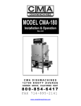
Introduction to CMA Model EST -66............................................................................................. 3
2.2.
Receiving and Installation .............................................................................................................. 4
2.2.1.
Box Item List ........................................................................................................................... 4
2.2.2.
Electrical ................................................................................................................................ 5
2.2.2.1.
Control Box Components ............................................................................................... 6
2.2.3.
Plumbing................................................................................................................................. 7
2.2.4.
Scrap Tray Assembly Installation ........................................................................................... 9
2.2.5.
Conveyor Drive/ Rack Speed ................................................................................................ 10
2.2.6.
Wash Pump Assembly and Impeller...................................................................................... 11
2.2.7.
Table Limit Switch Installation ............................................................................................. 12
2.2.8.
Optional Vent Hood Adapter’s Installation .......................................................................... 13
2.2.9.
Chemical Dispenser Connection .......................................................................................... 14
2.2.10. Optional Exhaust Fan Motor ................................................................................................ 14
2.2.11. (Optional) E-Temp Booster Heater ...................................................................................... 15
2.3. EST-66 Safety Tips ...................................................................................................................... 16
3.
OPERATION ........................................................................................................ 17
3.1.
Beginning Operation..................................................................................................................... 17
3.2.
Cleaning Instructions .................................................................................................................... 19
3.3.
Regular Service and Maintenance Checklist ................................................................................ 20
3.4.
Trouble Shooting .......................................................................................................................... 21
4.
EST-66 CUSTOMER NOTICE .............................................................................. 22
5.
PARTS MANUAL ................................................................................................ 24
5.1.
Initial Parts Kit ............................................................................................................................. 24
5.2.
Exploded View Drawings ............................................................................................................. 25
5.2.1.
5.2.2.
5.2.3.
5.2.4.
5.2.5.
5.2.6.
5.2.7.
5.2.8.
5.2.9.
5.2.10.
5.2.11.
5.2.12.
Cabinet Assembly ................................................................................................................. 25
Control Box Assembly .......................................................................................................... 26
Curtain and Optional Vent System ....................................................................................... 27
Old Wash Temperature Control System (Square Flange) .................................................... 28
New Wash Temperature Control System (Triangular Flange) ............................................. 29
Rinse Temperature Control System ...................................................................................... 30
Wash Pump Assembly ........................................................................................................... 31
Power Rinse Pump Assembly................................................................................................ 32
Drain System Assembly......................................................................................................... 33
Plumbing System Assembly (Auto-Fill) ................................................................................ 34
Plumbing System Assembly (Final Rinse)............................................................................. 35
Wash System Assembly ......................................................................................................... 36
www.cmadishmachines.com
5.2.13.
5.2.14.
5.2.15.
Rocker Arm Assembly ........................................................................................................... 37
Start Switch and Rinse Switch Assembly .............................................................................. 38
Optional E-Temp Heater ...................................................................................................... 39
6.
TABLE LIMIT SWITCH (P/N 13469.20) .......................................................... 40
7.
DRAIN WATER TEMPERING KIT (OPTIONAL) ........................................ 41
8.
ELECTRICAL DIAGRAM FOR 230V EST-66 ................................................ 42
9.
ELECTRICAL DIAGRAM FOR E-TEMP HEATER ONLY ......................... 43
10.
ELECTRICAL DIAGRAM FOR 480V EST-66 ................................................ 44
www.cmadishmachines.com
1. Specifications
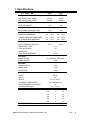
1.1. EST- 66
EST-66
L.T.
EST-66
H.T.
PER RACK (FINAL RINSE)
.49 GAL.
.49GAL.
PER HOUR (FINAL RINSE)
119 GAL.
119 GAL.
6.75
6.75
243
243
WATER CONSUMPTION
CONVEYOR SPEED
FEET PER MINUTE
OPERATING CAPACITY
RACKS PER HOUR (NSF rated)
OPERATING TEMPERATURE
WASH RECOMMENDED
140° - 150° F
150° - 160° F
PUMPED RINSE RECOMMENDED
140° - 150° F
150° - 160° F
FINAL RINSE RECOMMENDED
140° - 150° F
180° - 195° F
140° F
180° F
WATER REQUIREMENTS
INLET TEMPERATURE (MIN)
WATER INLET SIZE
1/2”
FINAL RINSE SIZE
1/2”
DRAIN SIZE
2”
FINAL RINSE PRESSURE
20 PSI
HEATERS
WASH HEATER
13.3 KW/240V, 10KW/208V
RINSE HEATER
3KW
MOTORS
WASH PUMP (2)
1 HP
RINSE PUMP
1/3 HP
CONVEYOR
1/8 HP
DIMENSIONS
DEPTH
25-1/8”
WIDTH
66”
HEIGHT
55 -1/2”-56-1/2”
STANDARD TABLE HEIGHT
32 ½” adjusts to 34”
MAX CLEARANCE FOR DISHES
19”
STRANDARD RACKS
ELECTRICAL RATING
19 ¾” x 19 ¾”
VOLTS
PHASE
AMPS
208
1
76
240
1
84
208
3
50
240
3
54
480
3
26
SHIPPING WEIGHT
MODEL EST-66 Installation and Operation Manual Rev. 1 .03
810#
(367kg)
Page
2
Getting Started
2. Getting Started
2.1.
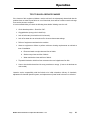
Introduction to CMA Model EST -66
The EST is designed to give maximum cleaning in 66 inches. It represents the cleaning power
of machines twice its length. The curtains incorporated in the dishwasher minimize the transfer
of water from tank to tank during the wash and sanitizing procedures.
The energy costs for running the new EST-66 have been greatly reduced, by the introduction of
our new Stage Washing Process. The EST-66 Conveyor dishwasher (EST is abbreviation for
ENERGY STAR) lowers gallon/rack ratings and is directly related to CMA’s new Power-Rinse
Stage that has been introduced. The EST-66 new Re-circulating Wash and new Power-Rinse
Stage greatly reduce the amount of chemicals being used, thus adding a significant cost
reduction and energy efficiency to its’ operation.
The EST-66 can be used as a high or low temperature dishwasher, with the new wash tank and
power rinse tank designs, both having their own re-circulating pumps. The Power Rinse Stage
provides a fresh cleansing rinse, before the dish rack advances into the Power Rinse and Fresh
Water and Sanitizing Rinse Stages.
The initial-fill water and the final rinse water that is supplied to the EST-66 must be a minimum of
140°F, in low-temperature applications, while high-temperature machines will require two water
lines; one at a minimum water temperature of 140°F to fill the dishwasher, and the second with a
minimum of 180°F for the final rinse. With the introduction of the new optional E-Temp Booster
Heater, it will be offered fully integrated to the dishwasher.
The EST-66 also features a stainless steel scrap accumulator tank and tray, which must be
emptied on a periodic basis, as necessary. The EST machine is designed to deliver 0.49 gallons
of fresh rinse water for each rack. This water flows from the rinse and power-rinse tanks into the
wash tank, and then overflows into the scrap tray, carrying any debris that may have fallen into
the wash tank, thereby providing a much cleaner environment for the washed and rinsed dishes.
If preferred, there are also options such as a Corner Feed System, optional Vent Hood Adapters,
Exhaust Fan Control Circuits and a Drain Tempering Kit. CMA also offers a full line of other
machine accessories, including stainless steel dishtables. (See equipment catalog)
DISCLAIMER OF LIABILITY OF WARRANTY: CMA EXPRESSLY DISCLAIMS ANY AND ALL WARRANTIES, EXPRESS OR IMPLIED, RELATING TO THE INSTALLATION OF ANY AND ALL
CMA EQUIPMENT THAT IS INSTALLED BY CHEMICAL DEALERS, CONTRACTED SERVICERS OR THIRD PARTY SERVICERS TO CMA EQUIPMENT.
IF THE INSTALLATION
INSTRUCTIONS ARE NOT FOLLOWED EXACTLY (TO THE LETTER), OR, IF ANY PERSON OR COMPANY CONDUCTING THE INSTALLATION OF THE CMA EQUIPMENT, REVISE THE
INSTALLATION PROCEDURES OR ALTER THE INSTRUCTIONS IN ANY MANNER, THE CMA WARRANTY BECOMES VOID. IF, DUE TO THE IMPROPER INSTALLATION OF CMA
EQUIPMENT, THIS EQUIPMENT CEASES TO OPERATE PROPERLY OR AFFECTS OTHER PARTS OF THE CMA DISHWASHING EQUIPMENT, IN THAT THE OTHER PARTS BECOME
DEFECTIVE, THE CMA WARRANTY BECOMES VOID. CMA WILL NOT BE LIABLE OR RESPONSIBLE OR WARRANT CMA EQUIPMENT, DUE TO IMPROPER INSTALLATION OF ANY
CMA MODEL DISHWASHER.
MODEL EST-66 Installation and Operation Manual Rev. 1 .03
Page 3
Getting Started
2.2.
Receiving and Installation
2.2.1. Box Item List
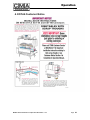
When you receive your new EST-66, prior to installation of the dishwasher, remove the box
containing the all items needed for the installation. (See item list below)
•
Literature & Manuals
•
Instructional Operation Video
•
Scrap Tank Assembly, w/Mounting Bracket
•
Curtains Interior and Exterior, w/Rods
•
Exterior Wrapper Shields
•
Installation Hardware
•
Operation Wall Chart
•
Optional Vent Hood Adapters when ordered.
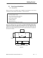
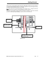
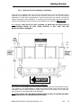
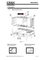
Start by first installing the Scrap Tray Assembly (see Scrap Tray Assembly, Section 2.2.4),
along with the Overflow Chute, then the two wrapper shields and the exterior and interior
curtains and rods, which are shipped inside the machine. All of the wash-arms are fully
installed over the wash and power-rinse tanks. There are a total of three curtains used in the
EST-66: two long-exterior curtains and one short-interior curtain, all with their own curtain rods.
(See Figure 2.2-1, below)
EST-66
3
1
4
2
5
6
SHORTWIDE
CURTAINS
LONG-NARROW
CURTAIN
LONG-NARROW
CURTAIN
DISH FLOW
DISHMACHINE FRONT VIEW
Figure 2.2.1
MODEL EST-66 Installation and Operation Manual Rev. 1 .03
Page
4
Getting Started
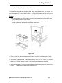
2.2.2. Electrical *
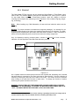
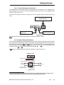
The CMA Model EST-66 Conveyor can be ordered as Single-Phase or Three-Phase, using
208v to 240v. The machine must be connected to a dedicated circuit. (See Figure 2.2.2 below
for amp draw). When installing a Three-Phase machine, check the voltage on all three
incoming lines, and place the highest leg on the L2 terminal. (This is called a high-leg, stingerleg, or Wild-leg.)
Note: When installing any CMA dishwasher, all state and local electrical codes must be
observed.
Warning: To prevent excessive overloads and component damages, it is essential for the
Dispenser Power Supply to be wired to the supplied Power Block on all conveyors. The CMAsupplied power block has been pre-wired to the wash heater contactor L1 and L3 terminals, to
assure a correctly balanced power, as well as accurate surrounding components.
Only for dispensers requiring constant power, connect to L1 and L3 of main contactor;
otherwise, use the Dispenser Power Block that has been provided.
Main Power
Knockout
Figure 2.2.2
On a 3-phase machine the water pump motors are also 3-phase and, depending on the terminal
that each phase is connected to, the motor can rotate in either direction. Check the direction of
rotation by removing the dust cap on the back of the motor. The motors must turn clockwise,
when looking at the shaft from the back of each motor. To change the direction of rotation,
switch any two power lead wires at the motor.
DANGER: ALWAYS TURN OFF THE DISHWASHER’S MAIN POWER SUPPLY BEFORE
SERVICING THE DISHWASHER. ALTHOUGH THE MACHINE’S MAIN POWER SWITCH IS
“OFF”, THE MAIN CONTACTOR LEADS WILL STILL HOLD VOLTAGE.
*
Electrical and plumbing connections must be made by a qualified person who will comply with all
available Federal, State, and Local Health, Electrical, Plumbing and Safety codes
MODEL EST-66 Installation and Operation Manual Rev. 1 .03
Page
5
Getting Started
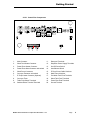
2.2.2.1. Control Box Components
15
A 1
T2
T1
L1
L2
L3
A 1
L2
L1
MAIN
CONTACTOR
WASH HEATER
CONTACTOR
L2
L1
T1
T2
L1
L2
L3
T3
T1
T2
L2
L3
A 1
WASH PUMP
CONTACTOR
T1
RINSE PUMP
CONTACTOR
T2
L1
T3
A2
L2
T1
T2
T3
T2
BOOSTER HEATER
CONTACTOR
A2
L3
L2
A 1
T1
T2
T3
L3
L2
WASH PUMP
CONTACTOR
T1
T2
T1
T3
A2
95
4
T3
1
2
3
9
10
11
7
6
5
12
3
GROUND
T2
95
L1
8
OVERLOAD
RELAY
7
2
L1
2
1
OVERLOAD
RELAY
6
T3
A2
3
CHEMICAL
DISPENSER
208-230V
T1
L3
CONVEYOR
CONTACTOR
T3
A2
T3
T2
L3
RINSE HEATER
CONTACTOR
T1
L3
A 1
POWER
SWITCH
L1
T3
20
13
AUTO
MANUAL
16
PRE-WASH
TANK
WASH
TANK
PRE-RINSE
TANK
17
18
19
14
1.
Main Contactor
11.
Detergent Terminals
2.
Wash Tank Heater Contactor
12.
Dispenser Power Supply Terminals
3.
Power Rinse Heater Contactor
13.
On-Off Power Switch
4.
Power Rinse Motor Contactor w/overload
14.
Auto/Manual Switch
5.
Wash Pump Contactors
15.
E-Temp Power Cable Knockout
6.
Conveyor Contactor w/overload
16.
Main Power Knockout
7.
E-Temp Heater Contactor (Optional)
17.
Pre-Wash Tank Float Terminals
8.
Conveyor Timer
18.
Wash Tank Float Terminals
9.
Table Limit Switch Terminals
19.
Power Rise Float Terminals
10.
Sanitizer/Rinse Terminal Terminals
20.
Ground Terminal
MODEL EST-66 Installation and Operation Manual Rev. 1 .03
Page
6
Getting Started
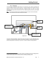
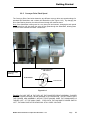
2.2.3. Plumbing *
The water supply connection is made with two ½” hot water lines; the valves are located at the
top of the machine, behind the main control box. The water supplied to the machine must be a
minimum of 140° F to the main fill valve and a minimum of 180° F to 195° F for a high
temperature final rinse, with no more than 140° F for a lower temperature final rinse. (See Figure
2.2.3a below)
Note:
The Low Temp machine can be supplied with single point water inlet kit with braided
hose included for fill and final rinse inlets connection.
Vacuum
Breaker
Main water inlet
valve connection ½”
Pressure
regulator
Final rinse water inlet
valve connection ½”
Figure 2.2.3a
To set the final rinse pressure, the final rinse must be running. Turn the adjustment screw
clockwise to increase final rinse pressure; and counter-clockwise to decrease the pressure set
the final rinse pressure to 20-psi ±5 psi. (Set to 22 - 23 psi for optimum running pressure)
*
Electrical and plumbing connections must be made by a qualified person who will comply with all
available Federal, State, and Local Health, Electrical, Plumbing and Safety codes
MODEL EST-66 Installation and Operation Manual Rev. 1 .03
Page
7
Getting Started
There are two 2” drain openings off both ends of the dishwasher, however only one connection
is on the horizontal drainpipe. Place the 2” drain plug, supplied in the end of the pipe not being
connected to the drain line (See Figure 2.2.3.b below).
Note: One of the ends of the horizontal drainpipe has a stopper cap on it – simply move the cap
to the other end, if it’s currently on the end needed for the drain connection.
The Scrap Tray Assembly is placed inside the machine for shipping. Follow the instructions
provided in 2.2.4 Scrap Tray Assembly to properly install to the dishmachine.
Scrap Tray
Main Drain & Scrap
Drain Connection
Drain Stopper
Cap
Main Drain Line from Wash &
Power Rinse Tanks
Figure 2.2.3b
MODEL EST-66 Installation and Operation Manual Rev. 1 .03
Page
8
Getting Started
2.2.4. Scrap Tray Assembly Installation
The Scrap Tray Assembly and Overflow Chute, which were shipped inside the machine, can
easily be installed by executing the following steps: Figure 2.2.4 below illustrates the assembly,
as it would appear for a Left-to-Right machine – (a Right-to-Left machine would simply be the
mirror image).
Caution:
1. For proper spacing, the SS flat washer must not be located between the head of the truss
head bolt and the inside of the machine.
2. The Illustration below shows the correct placements of the scrap trap holder. Do not
install upside down, otherwise water deflection takes place.
Figure 2.2.4
1. Remove items from their packaging and verify that all “installation hardware” was included.
2. Secure the scrap trap holder to the dishmachine by using the four ¼-20 X ½” Hex Head
Bolts, the ¼” SS Flat Washers, and the ¼”-20 Nylon Lock Nuts that were provided.
3. Set the scrap trap body—with the scrap trap drawer inserted—into position on the scrap trap
holder.
(Attach the drain as specified in Section 2.2.3)
MODEL EST-66 Installation and Operation Manual Rev. 1 .03
Page
9
Getting Started
2.2.5. Conveyor Drive/ Rack Speed
The Conveyor Drive Cam below shows the two different conveyor drive cam speed settings; for
standard 243 Racks/Hour and a slower 205 Racks/Hour (See Figure 2.2.5). By changing the
Drive Cam Bearing location, the racks will travel through the machine slower.
Note: If the dishwasher is being used in a very heavy soil environment, changing the rack speed
to 205 racks/hour will slow down the racks as they pass-through the dishwasher, allowing them
to receive more chemical and water “contact time”.
Conveyor Drive Cam
P/N 13505.14
Conveyor Cam
Bearing
205 RACKS/HOUR
243 RACKS/HOUR
Figure 2.2.5
Caution: DO NOT GET IN THE PATH OF THE CONVEYER DRIVE ASSEMBLY, ROCKER
ARM, OR CONVEYOR BAR, WHILE MACHINE IS IN OPERATION. DO NOT REACH INTO
THE ROCKER ARM ASSEMBLY WITHOUT FIRST MAKING SURE THE DISHWASHER IS
TURNED “OFF” AT THE MAIN PANEL. EVEN WITH THE MACHINE’S POWER SWITCH
“OFF”, THE MAIN CONTACTOR LEADS WILL STILL CARRY VOLTAGE.
MODEL EST-66 Installation and Operation Manual Rev. 1 .03
Page
10
Getting Started
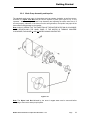
2.2.6. Wash Pump Assembly and Impeller
The standard wash pump motor is three-phase and can operate clockwise, as well as counterclockwise; the Nylon Lock Nut used to hold the impeller in place (See Figure 2.2.6), is very
important. When servicing the Wash Pump Assembly and replacing the seals, make sure it is
secured properly; otherwise, if the motor turns the wrong direction, the impeller may spin-off the
motor shaft causing damage to the impeller.
Note: ALWAYS CHECK THAT THE DIRECTION OF THE MOTOR ROTATION IS CLOCKWISE,
WHEN REINSTALLING THE WASH PUMP. IF THE MOTOR IS TURNING COUNTERCLOCKWISE, EXCHANGE L1 AND L3 WIRES ON MAIN CONTACTOR
Figure 2.2.6
Note: The Nylon Lock Nut indicated by the arrow in Figure 2.2.6 must be removed before
attempting to remove the water pump impeller.
MODEL EST-66 Installation and Operation Manual Rev. 1 .03
Page
11
Getting Started
2.2.7. Table Limit Switch Installation
The Model EST-66 is shipped with a Table Limit Switch fully wired and connected in the main
control box, ready to be installed on the clean side of the dishtable. The Table Limit Switch
MUST be installed to prevent dishrack and Conveyor Drive damage.
1. Remove the template that was shipped to hold the table-limit switch assembly
together.
2. Remove the activator bar (Figure 2.2.7a).
3. Position the template in the middle of the clean side of the dishtable.
4. Mark the end of the table, where the holes need to be drilled (Figure 2.2.7b).
5. Drill the holes.
6. Attach the Table Limit Switch, using the hardware supplied.
7. Reattach the activator bar removed earlier.
8. Test that it functions properly (Figure 2.2.7c).
Figure 2.2.7a
Figure 2.2.7b
Note: This terminal is not actual size ,not to be used
for installation!
Figure 2.2.7c
MODEL EST-66 Installation and Operation Manual Rev. 1 .03
Page
12
Getting Started
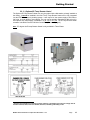
2.2.8. Optional Vent Hood Adapter’s Installation
CMA Vent Hood Adapters have been designed and engineered to draw only the steam that is
released from underneath the curtains at the entrance and exit of the EST-66 conveyor
dishwasher. This will allow the dishwasher to retain the heat within the machine, reducing the
energy consumption of the dishwasher. To maintain proper CFM’s (600), and not evacuate the
heat from the dishwasher tanks, CMA Vent Hood Adapters (PN # 13901.82) MUST be used.
Note: ON ALL PANT-LEG-STYLE VENT SYSTEMS, BY MODIFYING OR INSTALLING AN
UNAUTHORIZED BRAND OF VENT HOOD ADAPTER, IT WILL VOID THE CMA
MANUFACTURERS’ WARRANTY.
Exit
Entrance
Adjusting the internal baffles of the Vent Hood Adapters:
Once the vent hood adapters have been installed, completely close the internal baffle using two
7/16” wrenches. Run the dishwasher to create heavy steam buildup; start at the exit end of the
dishwasher, open the baffle enough to draw the steam into the vent system. Then repeat the
same process on the entrance side of the dishwasher.
Note: ONLY ONE OF THE TWO NUTS ON EACH BAFFLE IS USED TO TIGHTEN AND KEEP
THE INTERNAL BAFFLE FROM BEING REPOSITIONED.
MODEL EST-66 Installation and Operation Manual Rev. 1 .03
Page
13
Getting Started
2.2.9. Chemical Dispenser Connection *
The Model EST-66 will supply both the main power and the signals for the Detergent and
Sanitizer/Rinse Aid. Connect the chemical dispenser main power leads, to the supplied power
terminals. (See Figure 2.2.9)
Connect the Detergent and Rinse Aid signal wires to the supplied signal terminals (See Figure
2.2.9)
Dispenser Power only
208 to 240 Volts
Sanitizer/Rinse
Signal only
Detergent Signal only
Figure 2.2.9
Note: Sanitizer/Rinse and Detergent signals can draw more than 0.5 Amps.
2.2.10. Optional Exhaust Fan Motor
First, when field-installing the Optional Exhaust Fan Control, locate the detergent signal terminals
on the dispenser terminal block; mount the contactor, that was supplied with the kit, securely to
the control box; connect the Blue and Brown wires, also supplied in the kit, to the detergent signal
terminals; attach the power for the exhaust fans to the L1 and L2 incoming terminals of the
contactor, and the T1 and T2 terminals, to the exhaust fan.
Note: Wires for exhaust fan to be supplied by electrician. (See Figure 2.2.10)
TERMINAL BLOCK
DETERGENT SIGNAL
T2
L2
FAN CONTACTOR P/N 404.81
WIRES FROM THE
POWER SOURCE *
T1
L1
WIRES TO THE FAN
* 220 VAC OR 110 VAC
SUPPLIED BY ELECTRICIAN
Figure 2.2.10
*
Electrical and plumbing connections must be made by a qualified person who will comply with all
available Federal, State, and Local Health, Electrical, Plumbing and Safety codes
MODEL EST-66 Installation and Operation Manual Rev. 1 .03
Page
14
Getting Started
2.2.11. (Optional) E-Temp Booster Heater *
The Optional E-Temp Booster Heater can only be ordered with a dishwasher, already installed at
the factory; it cannot be installed in the field. The E-Temp Booster heater will be fully integrated
into the EST-66 conveyors’ plumbing system. It will require its’ own power supply of 208 volts to
240 volts, in single-phase or three-phase. The unit can be specially ordered as a 480-volt unit, in
three-phase only; temperature is available in a 40° rise or 70° rise. The E-Temp Booster heater
contactor is located in the EST-66 Main Control Box (See item 7, page 6).
Note: 70° degree rise E-temp Booster Heater is only available in Three-Phase.
*
Electrical and plumbing connections must be made by a qualified person who will comply with all
available Federal, State, and Local Health, Electrical, Plumbing and Safety codes
MODEL EST-66 Installation and Operation Manual Rev. 1 .03
Page
15
Getting Started
2.3.
EST-66 Safety Tips
DANGER:
Always turn off the main circuit breaker at the wall when
installing or servicing this dishmachine and/or an E-Temp
Booster Heater. Even with the machine’s power switch “off”,
there is a live connection being carried to the switch from the
dishmachine contactor.
CAUTION:
Do not get in the path of the Conveyor Rocker Arm or the
conveyor’s moving bar. Do not reach into the rocker arm area
without first making sure the dishmachine is turned “off” at the
circuit breaker.
CAUTION:
Do not open the front door when the machine is in operation.
CAUTION:
Avoid spraying water on or around the electrical control box
located on the top of the machine. When cleaning, do not
spray water directly on the motors.
CAUTION:
When removing the Final Rinse Arms for cleaning, exercise
caution. The Final Rinse Arms may be filled with chemicals or
have additional pressure applied.
MODEL EST-66 Installation and Operation Manual Rev. 1 .03
Page
16
Operation
3. Operation
3.1.
Beginning Operation
Figure 3.1
Step 1.Close both drains at
the bottom of machine (see
Fig.3.1 items 2,6 above)
MODEL EST-66 Installation and Operation Manual Rev. 1 .03
Step 2.Turn on main power and
machine will fill with water (see
Fig.3.1 item1 above)
Page 17
Operation
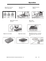
Step 3.Allow machine to
come to temperature
Step 4.Rinse rack
thoroughly
Step 6.Remove dishes
from rack
Step 8.Pre-soak flatware
Step 5.Place rack in
entrance
Step 7.Place
properly in rack
Step 9.Wash flatware
MODEL EST-66 Installation and Operation Manual Rev. 1 .03
Step 10.Place flatware in containers
with handles down; wash a second
time
Page
18
Operation
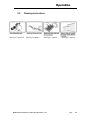
3.2.
Cleaning Instructions
See Fig.3.1, Items 2,6
See Fig.3.1, Items 4
See Fig.3.1, Items 5
MODEL EST-66 Installation and Operation Manual Rev. 1 .03
See Fig.3.1, Items 3
Page
19
Operation
3.3.
Regular Service and Maintenance Checklist
Check
all electrical connections, assuring they are tight and secure.
Check
all Water, Drain, and Plumbing connections for leaks; tighten if needed.
Check
Final Rinse Arms: the Rinse Jet Spray should be straight up & down.
Check
Wash Pump motor rotation, making sure it is turning clockwise.
Check
Dish rack Movement, Conveyor Arm & Bar, and Conveyor Dog Alignment.
Check
Tray Track Guide and Rail & Table Alignment throughout dishwasher.
Check
Timer Dipswitch Setting; only switch 6 should be in “on” position (32 seconds)
Check
Wash-Tank Temperature 150° F Minimum.
Check
Power-Rinse Tank Temperature 160° F Minimum.
Check
Final-Rinse Temperature 180° to 195° F (High-Temp)
(140° F for Low Temp)
Check
Final Rinse Pressure 20 psi, ±5 psi
Check
Table-Limit Switch operation (If not installed, Warranty will be voided)
Check
Vent Hood adapter baffle position to draw steam. (Optional)
(Keep baffles open to a minimum)
Check
and make sure the dishwasher is level.
Check
to make sure all curtains are in place.
Read
all labeling and follow procedures.
Review installation section before beginning the installation of the Model EST-66
Conveyor Dishwasher. All installation procedures and guidelines MUST BE followed
precisely.
MODEL EST-66 Installation and Operation Manual Rev. 1 .03
Page
20
Operation
3.4.
Trouble Shooting
PROBLEM
LIKELY CAUSE
SOLUTION
Wash or power rinse
Bad motor or capacitor
Replace defective motor or
motor not running
Faulty contactor
Replace contactor
Machine inoperative
Fuse is burned out
Replace fuse
Table limit switch
Remove dish rack at switch
Defective door reed switch
Replace reed switch
Defective start reed switch
Replace reed switch
Defective auto/manual switch
Replace switch
Defective Conveyor Timer
Replace timer
Timer or settings@ 60 Sec
Replace timer or change settings
Contactor stuck
Replace contactor
Float switch
Check movement-replace it
Defective thermostat or setting
Replace thermostat or adjust
Defective heater contactor
Replace heater contactor
Defective heater
Replace heater
Wire connections
Check and correct
Machine runs continuously
Heater (no heat)
Racks stuck
Wash & Power rinse tank
temperature low
Low final rinse pressure or
no rinse pressure
Machine using too much
chemical
Machine loosing water
Low wash arm pressure
Old or broken rack
Replace rack
Tray track alignment
Adjust track to table properly
Incoming water supply
Check hot water supply
(Low temp 120°F-Recommende140°F;
High temp 180°F minimum)
Thermostat setting
Adjust thermostat to mach NSF label
Vent hoods baffle setting
Set CMA Vent hood adapter baffles as
instructed on page 13
Plugged rinse jets
Remove and clean
Pressure regulator out of adjustment
Adjust pressure regulator20psi to 23psi
Water sol. valve coil or diaphragm
Replace or clean
Dirty rinse jets
Remove and clean jets
Defective rinse reed switch
Replace reed switch
Quick drain on wash end
Plumb quick drain back into wash tank
Dispenser or settings
Check dispenser troubleshooting guide
Rinse pressure
Set 20 psi.
Soil
Check scrap basket sand float function
Quick drain on dirty side table
Check quick drain connections
Sheet pans
Use CMA sheet pan rack
Drain valves open
Close completely
Debris In wash & power rinse arm
manifolds
Remove arm, check & clean debris from
manifolds
Clogged jets
Clean jets
Motors connected wrong
Connect motors to reverse impeller
direction
MODEL EST-66 Installation and Operation Manual Rev. 1 .03
Page
21
Operation
4. EST-66 Customer Notice
MODEL EST-66 Installation and Operation Manual Rev. 1 .03
Page 22
Operation
TIPS TO SAVE A SERVICE CHARGE
If the Lessee of this equipment initiates a service call and it is subsequently determined that the
problem does not relate to part failure or out of chemicals, there will be a minimum service charge
for a service person to respond.
It is recommended that you check the following items before initiating a service call:
Circuit breaker position. Should be “ON”.
Clogged drains (at any point in drain line).
Lack of soft water (check salt level in brine tank).
Lack of hot water due to valves shut off or incorrect thermostat settings.
Failure of equipment unrelated to the machine.
Abuse to equipment or failure to perform minimum cleaning requirements as outlined at
time of installation.
a. Rinse and wash arm tips clean and free of debris.
b. Strainer trays clean and free of debris.
c.
Water tank drains clean and free of debris.
Trip switch blocked or held from free movement due to a lodged utensil or dish.
Lines to chemical buckets found in wrong containers or empty. (Lines to the buckets are
color-coded.)
Lessee’s service responsibility shall be limited to its initial orientation, delivery of chemicals,
adjustment of chemical injection system, and replacement of parts found to be worn or defective.
MODEL EST-66 Installation and Operation Manual Rev. 1 .03
Page
23
Operation
5. Parts Manual
5.1.
Initial Parts Kit
P/N
DESCRIPTION
Qty
00120.02
Bi Metal Thermometer
1
00201.85
Pump Motor, 1HP, 3Ph, 60 Hz, 220V
1
00206.30
Pump Seal Kit
1
00208.21
Slip Joint Nut Friction Ring Plastic
1
00208.40
Slip Joint Nut Gasket
1
00225.00
1" Compression Gasket
1
00421.83
00556.60
Power Rocker Switch, Red
Reed Switch Magnet -ISI
1
1
00556.10
Reed Switch-ISI
1
00631.05
Ice Cube Relay 220V 12Amp
1
00707.00
½” Water Solenoid Repair Kit JE
1
00738.15
Solenoid Coil JE 220V
1
03202.00
Thermometer (Capillary)
1
03226.00
Pump O-Ring Gasket
1
03623.00
½ Vac Breaker Repair Kit Watts
1
13003.17
Contactor, 60-Amp
1
13003.50
Contactor, 30-Amp
1
13003.70
Toggle Switch SPDT 20AMP
1
13012.26
Motor Contactor, 220V
1
13403.26
Fuse, 3-Amp/250V Slow Blow
2
13415.47
Heater 3kW (GL-C & EST-66)
1
13417.80
Immersion Heater, 3Ph/1Ph, 208-230V, 10kW
1
13417.92
Heater Thermostat
1
13465.00
Liquid Level Switch, SS
1
13503.60
Rinse Pump - 1ph 208-240v 60HZ
1
13503.06
EST-44 Gear Motor Assy
1
13507.65
Cam Bearing Assy (New Dec 2007)
1
13508.70
Heavy Duty Clutch Spring
1
MODEL EST-66 Installation and Operation Manual Rev. 1 .03
Page
24
Operation
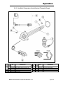
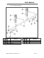
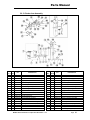
5.2.
Exploded View Drawings
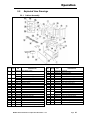
5.2.1. Cabinet Assembly
ITEM NO.
NO. REQ’D
1
1
P/N
13949.22
2
1
3
1
4
5
6
7
8
8A
9
10
11
12
13
14
15
1
2
4
4
1
1
1
27
60
52
2
8
2
13949.06
13949.16
13949.09
13949.19
01506.30
13901.10
01554.30
00636.10
13915.20
13910.06
00535.30
00905.00
00924.00
00912.00
13906.00
00914.10
13939.50
DESCRIPTION
ITEM NO.
NO. REQ’D
CMA-66/EST Stand
P/N
17
1
13913.00
Drip Chute
18
1
13542.00
Drip Chute Gasket
Foam Tape
Drain Valve Handle Support
Door Latch
Scrap Trap Body (Univ)
EST Scrap Trap Holder
Scrap Trap Drawer (Univ)
CMA-66 Splash Shield
Reed Switch Magnet -ISI
Reed Switch-ISI
Splash Shield Clip
L-R Curtain Splash Shield
R-L Curtain Splash Shield
Conveyor Bar Guide
8-32x1-1/2” Panhead Screw
8-32 Nylon Lock Nut
Door Latch Bracket Spacer
Bent Stem Single Float Switch
EST-44/66 Dual Float Switch
EST-66 Pan L-R Zoppas
EST-66 Pan R-L Zoppas
EST-66 Wrapper L-R
EST-66 Wrapper R/L
Door
Wrapper Shield
Door Guide
Door Guide Plastic
Door Latch Bracket
Door Latch Bracket W/Nut
Door Handle
1/4-20 x 1/2” Trusshead Bolt
1/4” Washer, SS
1/4-20 Nylon Lock Nut
Tray Track Rail
1/4-20 x 5/8” Hex Head Bolt
EST-44 Heater Cover
19
20
21
22
23
24
25
26
27
28
29
4
2
2
1
1
1
1
1
1
2
1
30
32
33
34
35
1
1
1
2
1
03705.00
13010.06
13701.00
01579.10
17579.20
01579.20
13912.36
00556.60
00556.10
13912.81
13704.08
13704.06
13522.00
00960.00
00927.00
13915.30
13465.30
36
1
13465.00
16A
3
13942.00
Strainer Basket, Wash/Rinse
16
1
13942.20
Strainer Basket EST-66 (3" deep)
MODEL EST-66 Installation and Operation Manual Rev. 1 .03
DESCRIPTION
Page 25
Operation
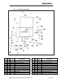
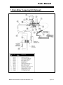
5.2.2. Control Box Assembly
ITEM NO.
NO. REQ’D
1
2
3
4
5
6
7
8
9
10
11
12
1
2
1
4
8
4
1
1
1
4
1
2
P/N
00449.50
13403.26
13941.12
00909.00
00924.00
13941.20
13003.17
13003.50
13013.45
13012.26
13426.50
03202.08
DESCRIPTION
ITEM NO.
NO. REQ’D
Lock, Keyless
Fuse, 3-Amp/250V Slow Blow
EST-44 Control Box Body
¼-20x3 ¼ SS Hexhead Bolt
¼ SS Washer
EST-44 Control Box Legs
Contactor 60 Amp 3 Pole
Contactor 30 Amp
EST-44 Conv Motor Overload
Motor Contactor, 220V
Ground Block
Thermometer Bracket
MODEL EST-66 Installation and Operation Manual Rev. 1 .03
13
14
15
16
17
18
19
20
21
22
23
24
2
1
1
1
1
1
1
1
1
4
2
1
P/N
03202.00
13013.40
00470.10
13003.70
00454.20
15520.00
00421.83
13003.60
13941.22
00912.00
13003.62
13418.60
DESCRIPTION
Thermometer
Overload Relay 2.5/4. 1/3 hp 1ph
Toggle Switch Rubber Boot
Toggle Switch SPDT 20AMP
8-Pole Terminal Block
Power Block 12-Position
Power Rocker Switch, Red
Starter DIN Rail
EST-44 Control box lid
¼-20 Nylon Lock Nut
Din Rail Mounting Bracket
Dip Switch Timer 230 V
Page 26
Operation
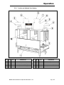
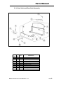
5.2.3. Curtain and Optional Vent System
ITEM NO.
NO. REQ’D
P/N
DESCRIPTION
ITEM NO.
NO. REQ’D
P/N
DESCRIPTION
1
1
13912.36
CMA-66 Splash Shield
6
2
13705.10
Curtain Rod Long
2
2
13702.25
Curtain CMA-44( 20-5/8” x 15”)
7
4
00914.10
1/4-20 X 5/8 Hexhead Bolt
3
1
13901.82
Hood Adapter EST-44 (2 pc set)
8
2
13901.12
CMA 44 Wash Curtain Support ('07)
4
2
13901.30
Outer Wrap Shield Curtain Support
9
4
00912.00
1/4-20 Nylon Lock Nut
5
2
13705.00
Curtain Rod Short
10
2
13702.35
Curtain CMA-44 (24 5/8" x 11-1/2”)
MODEL EST-66 Installation and Operation Manual Rev. 1 .03
Page 27
Operation
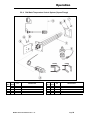
5.2.4. Old Wash Temperature Control System (Square Flange)
ITEM NO.
NO. REQ’D
1
2
3
4
1
1
1
1
1
P/N
DESCRIPTION
13417.75
13417.80
13465.00
13417.92
03202.00
Immersion Heater 3hp/1PH 380V 10kW
Immersion Heater 3Ph/1PH 240V 10kW
EST-44/66 Dual Float Switch
Heater Thermostat (EGO)
Thermometer
MODEL EST-66 Parts Manual Rev. 1 .02
ITEM NO.
NO. REQ’D
5
6
7
8
9
1
1
4
4
8
P/N
13416.10
13417.45
00901.00
13805.00
00926.00
DESCRIPTION
Thermostat Bracket
Heater Gasket
5/16 – 18 x 1” Hexhead Bolt
5/16 – 18 Nylon Nut
5/16” SS washer
Page 28
Operation
5.2.5. New Wash Temperature Control System (Triangular Flange)
ITEM NO.
NO. REQ’D
1
2
3
4
1
1
1
1
1
P/N
13422.78
13422.80
13465.00
13417.92
03202.00
DESCRIPTION
ITEM NO.
NO. REQ’D
380V 12KW Triangular Immersion Htr.
208V 10KW Triangular Immersion Htr.
EST-44/66 Dual Float Switch
Thermostat (EGO)
Thermometer
MODEL EST-66 Installation and Operation Manual Rev. 1 .03
5
6
7
8
1
4
4
8
P/N
15518.10
00914.00
00912.00
00924.00
DESCRIPTION
Heater Gasket
1/4-20 X 3/4 Hexhead Bolt
1/4-20 Nylon Lock Nut
1/4” SS washer
Page 29
Operation
5.2.6. Rinse Temperature Control System
ITEM NO.
NO. REQ’D
1
2
3
4
1
1
1
1
P/N
03202.00
13415.47
13465.00
13417.92
DESCRIPTION
Thermometer
Heater 3kW (GL-C & EST-66)
Float Switch
Thermostat (EGO)
MODEL EST-66 Installation and Operation Manual Rev. 1 .03
Page 30
Operation
5.2.7. Wash Pump Assembly
ITEM NO.
NO. REQ’D
1
2
3
4
5
6
7
8
9
2
2
2
2
2
2
2
2
2
P/N
DESCRIPTION
00201.85
03224.00
00206.30
03226.00
03222.10
04206.00
00208.40
04204.00
13916.40
Pump Motor, 1HP, 3Ph, 60 Hz, 220V
Pump Base Mount
Pump Seal Kit New
Pump O-Ring Gasket
Impeller (Open) SS
Pump Cover
Slip Joint Nut Gasket
Compression Nut, 2.5”
Motor Support Bracket
ITEM NO.
NO. REQ’D
10
11
12
13
14
15
16
17
18
MODEL EST-66 Installation and Operation Manual Rev. 1 .03
6
12
6
16
2
4
2
2
2
P/N
DESCRIPTION
00906.00
00922.00
00912.00
00921.00
13829.00
00238.00
04604.00
00200.85
00208.20
1/4-20 x 1/2” Hex Bolt
1/4” Lock Star Washer
1/4-20 Nylon Lock Nut
3/8-16 x 3/4” SS Hex Head Bolt
7/16-20 Thin Nylon Lock Nut
3/8” Male Plug
^35 Deg Elbow MIP X Barb SS
Motor Assembly, 1HP, 3Ph, 220V, 60 Hz**
Slip Joint Nut Friction Ring
*For EST-44 R-L only.
**Includes Items 1, 2, 3, 4, 5 and 14.
Page 31
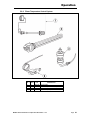
Parts Manual
5.2.8. Power Rinse Pump Assembly
ITEM NO.
NO. REQ’D
P/N
DESCRIPTION
ITEM NO.
NO. REQ’D
1
4
1
13503.60
03101.00
03108.66
DESCRIPTION
1
2
3
1
1
1
13503.70
13503.71
13503.72
Pump Head
Impeller
Seal Kit
4
1
13503.73
Pump O-Ring
12
1
03108.65
Transfer Hose 1” – 3-1/2”
5
1
13503.74
Back Plate
13
1
13916.45
EST-44 Final Rinse Motor Bracket
6
1
13503.75
Motor
14
3
00906.00
¼-20x1/2” Hex Bolt
7
1
13503.76
Capacitor
15
6
00922.00
¼-20 Lock Star Washer
8
1
13503.77
Cover
16
3
00912.00
¼-20 Nylon Nut
MODEL EST-66 Installation and Operation Manual Rev. 1 .03
9
10
11
P/N
Pump - 1ph 208-240v 60HZ
Hose Clamp # 16 1"
Transfer Hose 1” – 35”
Page 32
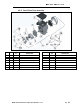
Parts Manual
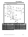
5.2.9. Drain System Assembly
ITEM NO.
NO. REQ’D
1
2
3
4
5
1
3
3
2
2
P/N
13001.85
20500.06
01317.17
13001.26
50109.00
DESCRIPTION
Drain Manifold
Waste Drain Valve
1-1/2” x 2” No Hub
CMA-44P Drain Support Bracket
Hose Clamp
MODEL EST-66 Service & Parts Manual Rev. 1 .03
ITEM NO.
NO. REQ’D
6
7
8
9
2
4
1
2
P/N
00912.00
00924.00
13024.00
00906.0
DESCRIPTION
1/4-20 Lock Nut
1/4“ Washer, SS
Dynamite Plug, 2”
1/4-20 x 1/2” Hex Head Bolt
Page33
Parts Manual
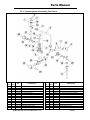
5.2.10. Plumbing System Assembly (Auto-Fill)
ITEM NO.
NO. REQ’D
P/N
DESCRIPTION
ITEM NO.
NO. REQ’D
P/N
DESCRIPTION
1
1A
1B
1
1
1
03624.00
03624.25
03623.00
1/2” Vacuum Breaker, Watts**
1/2” Vacuum Breaker Bonnet
1/2” Vacuum Breaker Repair Kit
9
10
11
1
1
1
41062.00
03603.15
00738.15
1/2 Strainer Ball Valve*
1/2” Water Solenoid Valve 220V, JE
2
3
4
5
6
7
8
2
1
2
1
2
3
1
00421.51
00739.50
00760.00
13608.00
41030.10
00742.00
00747.10
6-32 x 1/4” SS Panhead Screw
Vacuum Breaker Cap
5/8 Comp x 1/2 MIP Adapter
EST-44 Water Inlet Tube SS
1/2 90 Deg Ell Fx F Brass
Nipple Brass 1/2 x 1 1/2
Nipple Brass 1/2 x 5
12
13
14
15
16
17
1
1
1
1
1
1
03603.20
00786.00
00707.00
01525.06
00745.00
41062.10
1/2” Water Solenoid Valve Bonnet
Water Solenoid Plunger with Spring
1/2” Water Solenoid Valve Repair Kit
Plumbing Support Bracket
1/2 90 Deg Street Elbow
1/2 Ball Valve Strainer
MODEL EST-66 Installation and Operation Manual Rev. 1 .03
Water Solenoid Valve Coil, 220V, ¾” &1/2”
Page 34
Parts Manual
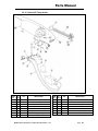
5.2.11. Plumbing System Assembly (Final Rinse)
ITEM NO.
NO. REQ’D
1
1A
1B
2
3
4
5
6
7
8
9
10
11
12
1
1
1
2
1
2
1
2
1
3
1
1
1
1
P/N
03624.00
03624.25
03623.00
00421.51
00739.50
00760.00
13608.50
03232.00
13669.21
00742.00
13620.20
00743.10
13307.00
00740.00
DESCRIPTION
1/2” Vacuum Breaker, Watts**
1/2” Vacuum Breaker Bonnet
1/2” Vacuum Breaker Repair Kit
6-32 x 1/4” SS Panhead Screw
Vacuum Breaker Cap
5/8 Comp x 1/2 MIP Adapter
44 Final Rinse Plibing Tube
1/8 Male Plug
Mixing Chamber SS
Nipple Brass 1/2 x 1 1/2
Street Elbow 1/2" SS 316
1/2” Tee, F x F x F
Final Rinse Tube, 23-1/2”
Coupling Adapter 1/2”x1/4”SS FxF
MODEL EST-66 Service & Parts Manual Rev. 1 .03
ITEM NO.
NO. REQ’D
13
14
15
16
17
18
19
20
21
22
23
24
25
26
1
1
1
1
1
1
1
1
1
3
1
1
3
1
P/N
00120.02
03603.15
00707.00
00786.00
03603.20
00738.15
13604.00
13605.45
00747.10
00745.00
13602.20
01525.06
13629.00
13630.00
DESCRIPTION
Bi Metal Thermometer
1/2” Water Solenoid Valve 220V, JE*
1/2” Water Solenoid Valve Repair Kit
Water Solenoid Plunger with Spring
1/2” Water Solenoid Valve Bonnet
Water Solenoid Valve Coil, 220V, ¾” &1/2”
1/2 x 1/4 Bushing Brass
Pressure Gauge (CMA-180)
Nipple Brass 1/2 x 5
1/2 90 Deg Street Elbow
1/2” Pressure Regulator
Plumbing Support Bracket
Nipple SS 1/2 x Close
Tee 1/2 FxFxF SS
Page35
Parts Manual
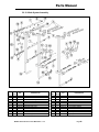
5.2.12. Wash System Assembly
ITEM NO.
NO. REQ’D
1
2
3
4
5
6
7
7A
8
9
10
10
4
2
6
6
2
2
8
2
4
3
P/N
13305.06
13327.06
13327.26
13303.16
04306.10
13310.00
13304.83
13304.66
13618.00
00721.20
13629.00
DESCRIPTION
Spray Arm End Cap
Socket Bracket, Double
Socket Bracket, Single
Spay Arm
Square Manifold Gasket
1/2” Cap, Brass
Final Rinse Spay Arm*
Final Rinse Spray Jets, SS
1/2” Coupling
1/2" Jamb Nut, Brass
1/2" Close Nipple, SS
MODEL EST-66 Service & Parts Manual Rev. 1 .03
ITEM NO.
NO. REQ’D
11
12
13
14
15
16
16A
17
18
19
20
1
1
1
1
1
1
1
48
96
48
1
P/N
13630.00
13307.00
13628.00
13301.12
13301.39
00213.00
00225.00
13305.40
00924.00
00912.00
13304.53
DESCRIPTION
1/2”F x F x F Tee, SS
Final Rinse Tube, 23-1/2”
1/2" 90° Elbow, F x F, SS
Wash Manifold
Rinse Manifold
1” Ford Adapter, MIP x PJ Tube**
1” Compression Gasket
Shoulder Bolt
1/4" SS Washer
1/4-20 Nylon Lock Nut
Long Support Bracket
Page36
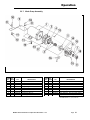
Parts Manual
5.2.13. Rocker Arm Assembly
ITEM NO.
NO. REQ’D
P/N
DESCRIPTION
ITEM NO.
NO. REQ’D
P/N
DESCRIPTION
1
2
1
1
13571.00
13503.06
EST Conveyor Drive Ass
EST-44 Gearbox Motor Ass
20
21
1
1
13809.00
00912.00
1/2-13 Nylon Lock Nut
1/4-20 Nylon Lock Nut
3
1
13505.14
EST-44 Drive Cam
22
1
13514.26
Conveyor Bar (8 Dogs) (CMA-66)
4
1
13505.20
Keyway (Cam)
23
8
13515.00
Conveyor Dog, SS
5
1
13507.20
Cam Bearing Only
24
1
13514.82
Left Conveyor Bar Bracket
6
1
13805.00
5/16-18 Nylon Insert Lock Nut
25
1
13514.84
Right Conveyor Bar Bracket
7
1
13507.11
Cam Bearing Shaft Spacer
26
1
13521.50
Conveyor Bar Slide Bearing
8
1
13507.12
Cam Bearing Shaft
27
8
13520.00
Conveyor Dog Bearing
9
2
00935.22
1/4-28 x 1/2" Brass Tip Set Screw
28
8
13806.00
3/8” Nylon Lock Nut
10
1
13816.00
5/16-18 X 1/2 Socket Set Screw
29
8
13818.00
3/8-16 x 1-3/4” Hex Head Bolt
11
1
13508.12
CMA 44 Rocker Arm
30
2
00924.00
1/4" SS Washer
12
2
13513.10
Rocker Arm Spacer
31
2
00914.10
1/4-20 x 5/8” Hex Head Bolt
13
2
13509.52
7/8” ID External Lock Ring
32
1
00903.00
1/4-20 x 1-3/4” Hex Head Bolt
14
2
13509.53
1” ID Brass Washer
33
1
13505.06
Cam Guide
15
16
17
18
19
1
1
2
4
1
13509.12
13510.10
00922.00
00914.00
13808.00
CMA 44 Rocker Shaft Bearing
Bearing Shaft
1/4" Lock Star Washer
1/4-20 x 3/4" Hex Head Bolt
1/2-13 x 3-1/2”
34
35
36
37
38
4
1
1
1
1
00912.00
13508.70
13508.26
13522.10
13507.65
1/4-20 Nylon Lock Nut**
Heavy Duty Clutch Spring
Rack Saver Clutch Bar
Conveyor Bar Guide
Cam Bearing Assy (12/07)
MODEL EST-66 Installation and Operation Manual Rev. 1 .03
Page 37
Parts Manual
5.2.14. Start Switch and Rinse Switch Assembly
ITEM NO.
NO. REQ’D
1
2
3
4
5
6
7
8
9
10
11
1
4
1
1
1
1
4
4
4
4
1
P/N
13408.61
00907.50
00556.60
13408.62
00556.10
13408.63
00965.00
00924.00
00906.00
00912.00
13408.60
DESCRIPTION
Actuator Arm
6-32 x 3/8” Pan Head Screw
Reed Switch Magnet-ISI
Actuator Bracket
Reed Switch-ISI
Reed Switch Bracket
6-32 Nylon Lock Nut
¼” SS Washer
¼” –20 x ½” Hex Head Bolt
¼” – 20 Nylon Lock Nut
Actuator Assy.
MODEL EST-66 Service & Parts Manual Rev. 1 .03
Page38
Parts Manual
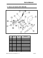
5.2.15. Optional E-Temp Heater
ITEM
NO.
NO. REQ’D
P/N
DESCRIPTION
ITEM NO.
NO. REQ’D
P/N
DESCRIPTION
1
1
13620.20
Booster Heater 1/2 In/Out Adapter
9
6
00924.00
1/4 SS Washer
2
2
40014.00
1/2m x 1/2 Barb Straight
10
6
00912.00
1/4-20 Nylon Lock Nut
3
4
03101.00
Hose Clamp # 16 1"
11
1
17523.51
Hi Limit Switch 250Deg
4
AR
03107.50
Flexible Black Hose 1/2" Horizon
12
1
40116.00
1/4 Comp x 1/4 MIP Ftg
5
1
13951.10
E-Temp Booster Shroud - Zoppas
13
1
13417.92
Heater Thermostat
6
1
13951.12
E-Temp Booster Access Cover
14
1
13422.72
240V 10KW Triangular Immersion Htr*
7
2
15518.10
Gasket for Triangular Flange Heater
15
1
13951.20
E-Temp Heater Tank (40F Rise)
8
1
13950.20
E-Temp Tank Plug
MODEL EST-66 Installation and Operation Manual Rev. 1 .03
* Note : Use two heaters for 70 F Rise.
Page 39
Parts Manual
6. Table Limit Switch (P/N 13469.20)
ITEM
NO.
1
2
3
4
5
6
7
8
9
10
11
12
13
14
15
16
NO. REQ’D
P/N
12 FT
1
1
2
24 FT
1
1
1
1
2
2
2
2
2
2
1
00400.00
00401.00
00402.00
00446.00
00529.00
13427.60
13427.61
13427.62
13427.63
03817.00
03814.10
00914.10
00968.00
00924.00
00912.00
13427.10
MODEL EST-66 Service & Parts Manual Rev. 1 .03
DESCRIPTION
Conduit 3/8 sealtite
ST-3/8 straight connector
ST-90 deg.3/8 connector
Fork tongue connector
Wire 18 gauge black
Template kit
Mounting bracket
Actuator
Bumper
6-32 wing nut
Lock star washer
1/4-20 x 5/8 hexhead bolt
1/4 split lock washer
1/4 ss washer
1/4-20 nylon lock nut
Limit switch
Page40
Parts Manual
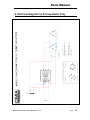
7. Drain Water Tempering Kit (Optional)
MODEL EST-66 Installation and Operation Manual Rev. 1 .03
Page 41
Parts Manual
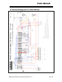
8. Electrical Diagram For 230V EST-66
MODEL EST-66 Installation and Operation Manual Rev. 1 .03
Page 42
Parts Manual
9. Electrical Diagram For E-Temp Heater Only
MODEL EST-66 Service & Parts Manual Rev. 1 .03
Page
43
MODEL EST-66 Service & Parts Manual Rev. 1 .03
T1
L2
L1
2
7
POWER
SWITCH
3
TRANSFORMER
* AMP FUSE
SLOW BLOW
(x2)
L3
L2
L3
T1
T2
PRE-WASH
TANK
TANK
HEATER
10kW
T3
WASH HEATER
CONTACTOR
L1
* 250 VA Transformer:
440 Volt application - 1.8 Amp
480 Volt application - 1.5 Amp
* 350 VA Transformer - 1.8 Amp
GROUND
T2
MAIN
CONTACTOR
T3
L2
L3
T1
T3
WASH
TANK
L1
L2
L3
T2
T3
T2
T3
A2
A1
PRE-RINSE
TANK
L2
L3
T1
PUMP
MOTOR
T2
T3
WASH PUMP
CONTACTOR
L1
RINSE
THERMOSTAT
PUMP
MOTOR
DOOR
SAFETY
SWITCH
T1
OVERLOAD
RELAY
T1
RINSE PUMP
CONTACTOR
95
WASH
THERMOSTAT
TANK
HEATER
3 kW
T2
RINSE HEATER
CONTACTOR
L1
A2
A 1
L2
L3
T2
PUMP
MOTOR
T3
A2
A 1
L2
L3
95
T2
T3
T1
CONV
MOTOR
T2
T3
OVERLOAD
RELAY
T1
CONVEYOR
CONTACTOR
L1
A2
A1
3
CYCLE START
TRIP SWITCH
2
DOOR
SAFETY
SWITCH
1
6
AUTO
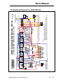
5: COMBINED LOAD OF USER DEVICES (CHEMICAL PUMPS, FAN CONTROLS, ETC.) MUST NOT EXCEED 1.5 AMPS.
4: DETERGENT FEEDER CONNECTIONS AND SIGNAL FOR FAN MOTOR CONTROL CONTACTOR COIL.
WATER
SOLENOID
VALVE
WATER
SOLENOID
VALVE
RINSE
NOTE 4, & 5
2: SANI/RINSE. POWER IS ON WHEN FINAL RINSE IS ACTIVE.
3: CONNECT ONLY TO PRIMARY OF LISTED CLASS 2 TRANSFORMER 208-230V 60Hz MAXIMUM 100VA.
MANUAL
FINAL RINSE
TRIP SWITCH
NOTE 1
NOTE 2, 3 & 5
1: REMOVE JUMPER FOR OPTIONAL TABLE LIMIT SWITCH CONNECTION.
NOTES:
T1
WASH PUMP
CONTACTOR
L1
CONVEYOR
TIMER
220V SIGNAL FOR USER SUPPLIED
FAN MOTOR CONTROL CONTACTOR
COIL.
12/22/2009
Rev. 1.00
}
w/TRANSFORMER: 480/575/600, DUAL FLOATS.
WIRE DIAGRAM FOR MODEL: EST-66
Parts Manual
10. Electrical Diagram For 480V EST-66
Page
44