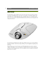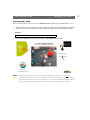
1
U S E R S G U I D E V.1.1.
AXIS 2100
NETWORK
CAMERA
Live web
images unleashed.
AXIS 2100 User’s Guide
Quick Network Installation Procedure
Quick Network Installation Procedure
Follow the instructions below to quickly install the AXIS 2100 on an Ethernet network.
If you do not have a network and intend to use a modem with your AXIS 2100, please refer to the
UsingYour Camera with a Modem section of this User’s Guide.
1. Note the serial number found on the underside label of the AXIS 2100. The Ethernet address
is the same as the serial number of the unit.
2. Acquire a valid and unused IP address for the AXIS 2100 from your Network Administrator.
Assign the IP address using the ARP command, as described below:
Windows 95/98 & NT/2000 only - Start a DOS window and type these commands:
Syntax:
Example:
arp -s <Server IP address> <Ethernet address> <my PC IP address>
ping -t <Server IP address>
arp -s 172.21.1.200 00-40-8c-10-00-86 172.21.1.193
ping -t 172.21.1.200
UNIX only - Type these commands:
Syntax:
Example:
arp -s <IP address> <Ethernet address>
temp ping <IP address>
arp -s 172.21.1.200 00:40:8c:10:00:86
temp ping 172.21.1.200
You will now see the message ‘Request timed out...’, repeatedly returned in the window.
3. Connect your AXIS 2100 to the network and external power supply.
To verify that the address has been set and that communication is established, ping the unit
once again with the new IP address; the host then returns: ‘Reply from 172.21.1.200...’ or
similar.
4. To access the AXIS 2100 Home Page, start the Web browser and enter the IP address in the
location/address field:
Syntax:
http://<IP address>/
Example:
http://172.21.1.200/
5. With reference to the on-line help, start the Installation Wizard and configure your
application.
Note: •If you are installing many units on to your network, please refer to the AXIS IP Installer information under the section Installing Your Camera on a Network in this User’s Guide.
AXIS 2100
Network Camera
User’s Guide
AXIS 2100 User’s Guide
2
About This Document
Liability
This document is intended for administrators and users of the
AXIS 2100 Network Camera, and is applicable for software
release 2.03. Although many of the operational aspects of the
product are described in the on-line help, this guide does contain
information for configuring, managing and using the unit in
your networking environment, as well as a general overview of
the product functionality.
Every care has been taken in the preparation of this manual; if you
detect any inaccuracies or omissions, please inform your local Axis
office. Axis Communications AB cannot be held responsible for any
technical or typographical errors and reserves the right to make
changes to the product and manuals without prior notice. Axis
Communications AB makes no warranty of any kind with regard to
the material contained within this document, including, but not
limited to, the implied warranties of merchantability and fitness for a
particular purpose. Axis Communications AB shall not be liable nor
responsible for incidental or consequential damages in connection
with the furnishing, performance or use of this material.
Readers are recommended to use this document as a supplement
to the Wizards and other online information available via the
Web-based interface. Later versions of this document will be
posted to the Axis Website, as required.
Safety Notices
Trademark Acknowledgments
Please observe all safety markings when using this product.
Caution! - Potential hazard that can damage the product.
Acrobat, Adobe, Boa, Ethernet, IBM, Internet Explorer, LAN
Manager, Linux, Macintosh, Microsoft, Netscape Navigator, OS/2,
UNIX, Windows, WWW are registered trademarks of the respective
holders. Java and all Java-based trademarks and logos are trademarks
or registered trademarks of Sun Microsystems, Inc. in the United
States and other countries. Axis Communications AB is independent
of Sun Microsystems Inc.
Important! - Potential hazard that can seriously impair
operation.
Do not proceed beyond any of the above notices until you have
fully understood the implications.
Legal Considerations
Camera surveillance can be prohibited by laws that vary from
country to country. Check the laws in your local region before
using the AXIS 2100 for surveillance.
Electromagnetic Compatibility (EMC)
USA - This equipment generates, uses, and can radiate radio
frequency energy and if not installed and used in accordance
with the instruction manual, may cause interference to radio
communications. It has been tested and found to comply with
the limits for a Class A computing device pursuant to Subpart B
of Part 15 of FCC rules, which are designed to provide
reasonable protection against such interference when operated in
a commercial environment. Operation of this equipment in a
residential area is likely to cause interference, in which case the
user at his/her own expense will be required to take whatever
measures may be necessary to correct the interference. Shielded
cables should be used with this unit to ensure compliance with
the Class A limits.
Europe
- This digital equipment fulfills the
requirements for radiated emission according to limit B of
EN55022/1994, and the requirements for immunity according
to EN55024/1998 residential, commercial, and light industry.
AXIS COMMUNICATIONS
<Product
Name> Quick User’s Guide
Support Services
Should you require any technical assistance, please contact your local
dealer. If your questions cannot be answered immediately, your dealer
will forward your queries through the appropriate channels to ensure
you a rapid response. If you are connected to the Internet, you can
obtain on-line manuals, technical support, software updates,
application software and general corporate information from
www.axis.com.
AXIS 2100 User’s Guide
Revision 1.1
Part No: 18304
Dated: December 2000
Copyright © Axis Communications AB,
1996 - 2000
AXIS 2100 User’s Guide
Table of Contents
Table of Contents
Overview . . . . . . . . . . . . . . . . . . . . . . . . . . . . . . . . . . . . . . . . . . . . . . . . . . . . . . . . . . . . . . . . . 4
Features and Benefits . . . . . . . . . . . . . . . . . . . . . . . . . . . . . . . . . . . . . . . . . . . . . . . . . . . . . . . 5
Physical Description . . . . . . . . . . . . . . . . . . . . . . . . . . . . . . . . . . . . . . . . . . . . . . . . . . . . . . . . . 7
Front Panel . . . . . . . . . . . . . . . . . . . . . . . . . . . . . . . . . . . . . . . . . . . . . . . . . . . . . . . . . . . . . . . . 7
Rear Panel . . . . . . . . . . . . . . . . . . . . . . . . . . . . . . . . . . . . . . . . . . . . . . . . . . . . . . . . . . . . . . . . 8
Assembling Your Camera . . . . . . . . . . . . . . . . . . . . . . . . . . . . . . . . . . . . . . . . . . . . . . . . . . . . . 9
Checking the Hardware Inventory . . . . . . . . . . . . . . . . . . . . . . . . . . . . . . . . . . . . . . . . . . . . 9
Connecting the AXIS 2100 to a Mounting Assembly . . . . . . . . . . . . . . . . . . . . . . . . . . . . . 9
Choosing Your Application . . . . . . . . . . . . . . . . . . . . . . . . . . . . . . . . . . . . . . . . . . . . . . . . . . 10
Networking Applications . . . . . . . . . . . . . . . . . . . . . . . . . . . . . . . . . . . . . . . . . . . . . . . . . . . 10
Modem Applications . . . . . . . . . . . . . . . . . . . . . . . . . . . . . . . . . . . . . . . . . . . . . . . . . . . . . . . 15
Installing Your Camera on a Network . . . . . . . . . . . . . . . . . . . . . . . . . . . . . . . . . . . . . . . . . . 20
Quick Installation Procedure . . . . . . . . . . . . . . . . . . . . . . . . . . . . . . . . . . . . . . . . . . . . . . . .
Verifying the Installation From Your Browser... . . . . . . . . . . . . . . . . . . . . . . . . . . . . . . . . .
Alternative Methods of Assigning the IP Address . . . . . . . . . . . . . . . . . . . . . . . . . . . . . . .
Using Your Camera with a Modem . . . . . . . . . . . . . . . . . . . . . . . . . . . . . . . . . . . . . . . . . . . .
20
22
23
26
Before You Begin . . . . . . . . . . . . . . . . . . . . . . . . . . . . . . . . . . . . . . . . . . . . . . . . . . . . . . . . . 26
Adjusting the Camera Focus . . . . . . . . . . . . . . . . . . . . . . . . . . . . . . . . . . . . . . . . . . . . . . . . . 32
The Focus Assistant . . . . . . . . . . . . . . . . . . . . . . . . . . . . . . . . . . . . . . . . . . . . . . . . . . . . . . . 32
Replacing the Lens . . . . . . . . . . . . . . . . . . . . . . . . . . . . . . . . . . . . . . . . . . . . . . . . . . . . . . . . 34
Configuring Your Camera . . . . . . . . . . . . . . . . . . . . . . . . . . . . . . . . . . . . . . . . . . . . . . . . . . . 35
Configuration Using the Wizards . . . . . . . . . . . . . . . . . . . . . . . . . . . . . . . . . . . . . . . . . . . .
The Administration Tools . . . . . . . . . . . . . . . . . . . . . . . . . . . . . . . . . . . . . . . . . . . . . . . . . .
Reinstating the Factory Default Settings . . . . . . . . . . . . . . . . . . . . . . . . . . . . . . . . . . . . . . .
Appendix A - Troubleshooting . . . . . . . . . . . . . . . . . . . . . . . . . . . . . . . . . . . . . . . . . . . . . . .
35
36
40
41
Frequently Asked Questions . . . . . . . . . . . . . . . . . . . . . . . . . . . . . . . . . . . . . . . . . . . . . . . .
PINGing Your IP Address . . . . . . . . . . . . . . . . . . . . . . . . . . . . . . . . . . . . . . . . . . . . . . . . . . .
Problems, Possible Causes and Remedial Actions . . . . . . . . . . . . . . . . . . . . . . . . . . . . . .
Appendix B - Updating the Software . . . . . . . . . . . . . . . . . . . . . . . . . . . . . . . . . . . . . . . . . . .
41
42
43
46
Appendix C - The Unit Connectors . . . . . . . . . . . . . . . . . . . . . . . . . . . . . . . . . . . . . . . . . . . 47
Appendix D - High Speed Services . . . . . . . . . . . . . . . . . . . . . . . . . . . . . . . . . . . . . . . . . . . . 52
Appendix E - Technical Specifications . . . . . . . . . . . . . . . . . . . . . . . . . . . . . . . . . . . . . . . . . . 54
Index . . . . . . . . . . . . . . . . . . . . . . . . . . . . . . . . . . . . . . . . . . . . . . . . . . . . . . . . . . . . . . . . . . . . 55
Glossary of Terms . . . . . . . . . . . . . . . . . . . . . . . . . . . . . . . . . . . . . . . . . . . . . . . . . . . . . . . . . 57
3
4
Overview
AXIS 2100 User’s Guide
Overview
The AXIS 2100 is a digital TCP/IP network camera that includes all of the required networking
connectivity for distributing images or live video over an intranet, or the Internet. With its own
built-in Web server, it allows high-quality remote surveillance images to be viewed directly from
any browser on the network, and provides full Web-based control of the various management and
configuration functions.
Use the camera for intruder detection, bank security, child protection, process control, industrial
and public surveillance, visual security, image archiving, or any other application requiring remote
monitoring.
Designed using an open-network structure, the AXIS 2100 minimizes the need for costly and
complex coaxial cabling - to press your installation overhead and provide you with an advanced yet
cost-effective network imaging solution. None of the hidden accessories normally associated with
digital cameras are required.
AXIS 2100 User’s Guide
Overview
Features and Benefits
Easy to Use - The AXIS 2100 is completely independent of any other server and requires no other
special hardware or software such as PC frame grabber cards or viewing software. All you need is
Netscape Navigator 4.x or above. Alternatively, you can use the Axis ActiveX component for
Microsoft Internet Explorer 4.x or above. If your computer does not allow you to use ActiveX
components, use the Java Applet instead. The AXIS 2100 has complete plug-and-picture
functionality - all you need do is assign a valid IP address.
Simple Installation - Connecting directly to Ethernet or Fast Ethernet networks, the AXIS 2100
is a standalone digital camera that will also connect to your local Internet Service Provider using an
external modem. Its Web-based interface features several user-sensitive Wizards that simplify the
installation process, and provide for a seamless and automated integration into your networking
and application environments.
Open Standards Environment - Supporting TCP/IP, SMTP e-mail, HTTP and other
protocols, the AXIS 2100 can be used in mixed environments, such as Windows, UNIX,
Macintosh and OS/2. Integrates easily into other WWW/Intranet applications and CGI scripts.
Simple Administration - Configuration and management via the product’s own Web-based
Administration Tools. Image control, time stamping and text overlays are all accessible from the
tools.
Standard Image Format - The AXIS 2100 delivers complete, high-quality pictures in standard
JPEG format, which can be viewed using any standard browser.
High Compression and Sensitivity - The fully configurable compression features afforded by
the AXIS ARTPEC chip allow a normal quality image to be compressed to around 8 kbytes. Actual
file sizes vary according to lighting conditions; although the product works well even in dark
environments - right down to 3 lux.
Standard Lens - Standard CS wide-angle lens with rotational focus control. A C-lens can also be
used together with a CS-C adaptor. Any other lens conforming to the same standard can also be
used.
External Device Connection - Can be used with IR-sensors, switches and alarm relays.
5
6
Overview
AXIS 2100 User’s Guide
ISP and Modem - The Point to Point Protocol (PPP) support allows you to use your AXIS 2100
remotely over a serial link, just as if it were located on your local network. Initially setting up the
unit using a computer connected by the supplied Null Modem cable, you can quickly configure
the unit for remote use using an external modem; whereby your video images can even be uploaded
to your preferred Internet Service Provider (ISP) to allow global access to your live images from any
browser on the Internet. Select any of the supported ISPs in the Web-based Wizards, or use your
own ISP as storage for your live images.
Security - The AXIS 2100 includes a self-contained Web server, which means that digital images
can be secured like any other Internet host. Data protection is normally implemented by your
Network Administrator using the unit’s security settings in combination with an organization’s
Internet firewall. The Administrator can decide whether individuals, groups, the whole company
or the whole world may access your camera. The AXIS 2100 supports multi-user password
protection.
Network Camera Servers Developer's Pages - The Camera Division at Axis maintains a
specialist site for network camera developers. New ideas and tools for software developers are often
added. Follow the camera links and check it out at: www.axis.com/
Linux Operating System - Including a Boa Web server, the Linux operating system provides a
stable platform for open-source development in future releases of the product. In accordance with
the GNU General Public License, Axis have published the kernel for this product at
http://developer.axis.com/. Axis would like to thank Paul Phillips, who wrote Boa; and Larry
Doolittle, who is now enhancing and maintaining this free software - published at www.boa.org.
AXIS Technology - Axis renowned chipset technology is built upon an open architechture that is
streamlined to provide device connectivity independent of any file server. The AXIS 2100 is driven
by a powerful AXIS ETRAX 32-bit RISC processor and includes the industry's first dedicated
digital video remote monitoring compression chip - the AXIS ARTPEC-1.
Compression and Performance - With an adaptive frame rate dependent on the prevailing
lighting conditions, the AXIS 2100 delivers Motion-JPEG images at up to 10 images per second, as
well as single JPEG images that feature user-defined compression levels. See also Picture frequency
for Networking Applications, on page 11.
Complimentary Software • AXIS IP Installer - for quick installation of multiple units
• AXIS Camera Control (Axis’ ActiveX component software, required for Microsoft Internet
Explorer).
• Java Applet for use with Internet Explorer when ActiveX cannot be used.
AXIS 2100 User’s Guide
Physical Description
Physical Description
Read the following information to familiarize yourself with the AXIS 2100, making particular note
of where the connectors and indicators are located. This information provides a useful reference
during the installation of the product.
Front Panel
Status Indicator
Used in conjunction with the Focus Assistant, this multi-colored indicator can be configured
for use as a local focusing aid (for further details please refer to Adjusting the Camera Focus, on
page 32). Under normal conditions however, this indicator shows the operational status of
the camera, as described below:
•
green - the indicator flashes briefly and momentarily displays orange during the
start-up and self-test routines. The indicator then displays green to indicate a healthy
unit status.
• red - the indicator will display red only if a problem with the AXIS 2100 has occurred.
Refer to Appendix A - Troubleshooting.
Note: The Status indicator also displays orange when re-setting to the factory default settings,
as described in Reinstating the Factory Default Settings, on page 40.
Lens Assembly
Includes a wide
angle lens with
rotational focus
control.
The supplied lens
is removable and
can be replaced
with any standard
C/CS lens.
Serial Number
Located on the
underside label of
the AXIS 2100, the
serial number is
identical to the
Ethernet address of
the unit.
Control Button
Located to the left of the lens assembly; this button is recessed within the product casing.
Using a suitably pointed object, press this button to restore the factory default settings as
described in Reinstating the Factory Default Settings, on page 40; or enable the Focus Assistant,
as described in Adjusting the Camera Focus, on page 32.
Caution!
The AXIS 2100 Network Camera is intended for indoor use only. Prolonged exposure to direct sunlight
or halogen light may damage the CCD. The Axis warranty does not cover CCD damage caused by prolonged exposure to strong light.
7
8
Physical Description
AXIS 2100 User’s Guide
Rear Panel
Network Connector
The AXIS 2100 is designed
for 10 Mbps Ethernet and
100 Mbps Fast Ethernet
networks and connects to
the network via a twisted
pair category 5 cable
(10baseT and 100baseTX)
terminated using a standard RJ-45 connector.
Supporting NWAY, the
AXIS 2100 detects the
speed of the local network
segment and varies the
speed of data communication accordingly, between
10 Mbps and 100 Mbps.
Network Indicator
Power Indicator
After completion of the startup and self test routines, this
multi-colored indicator flashes independently, as follows:
Normally lit when
power is applied. If it
is not lit, or it flashes,
there is a problem
with the AXIS 2100
external power
source.
•
•
•
yellow - activity on a 10Mbps network
green - activity on a 100Mbps network
red - no physical connection to the network
I/O Connector
Provides the physical interface to a digital output, and a single digital photo-coupled
input that is used for connecting a variety of external alarm devices to the AXIS
2100; including, IR-sensors, switches and alarm relays. In combination with the configurable alarm facilities, you can quickly develop a variety of security applications that
are triggered on time - or alarm based - events. The connector can also be utilized as
an alternative connection point for DC supply to the unit.
Power Supply
Connector
A single Jack socket
(PS-D) for connection of AXIS 2100
power supply. The
terminal block connector provides an
auxiliary connection
point for AC or DC
power to the unit.
RS-232 Serial Connector
Single 9-pin D-sub connector
providing the RS-232 serial
interface dedicated for modem
connection.
Note: The power supply supplied with your AXIS 2100 is country specific. Please check that the type of
power supply you are using is correct. See page 9.
AXIS 2100 User’s Guide
Assembling Your Camera
Assembling Your Camera
The information provided in this section will help you unpack and assemble your product; you are
then ready to proceed with the installation and configuration of the product into your application
environment, as described in the following sections of this document.
Checking the Hardware Inventory
Unpack and check all the items against the itemized list below. You should contact your dealer
immediately if you find anything is missing or damaged.
Hardware
Model Variants
Digital Camera
AXIS 2100
Part Numbers
0106-001-01
Null Modem Cable
-
16954
Mounting Assembly
-
15104
Power Supply (PS-D)
Europe
14233
UK
14234
Australia
14255
USA
14253
Japan
14254
PS-D Extension Cable
3.3 meter
15187
Printed Materials
AXIS 2100 Installation Guide 1.0
17824
AXIS 2100 Warranty
17438
AXIS Network Camera CD 1.1
17944
Media
Connecting the AXIS 2100 to a Mounting Assembly
Caution!
When assembling your camera, please note that the AXIS
2100 is specifically intended for indoor use only, and that the
charged coupled device (CCD) in the camera will become permanently damaged if the lens is exposed to too much direct
sunlight or halogen light! The Axis warranty does not cover
CCD damage caused by prolonged exposure to strong light.
The mounting assembly supplied with your AXIS 2100 features
a screw head that attaches to the underside of the product.
Fasten the AXIS 2100 to the mounting assembly and position it appropriately for your application;
three holes in the base unit allow the product to be securely fastened to any wall or ceiling.
Note: If you need to mount your camera upside-down, the AXIS 2100 can be easily configured to flip
images through 180o.
9
10
Choosing Your Application
AXIS 2100 User’s Guide
Choosing Your Application
The AXIS 2100 can be used in a wide variety of applications. Installing directly onto an Ethernet
network or via a V.90-compatible modem, the product is completely independent and requires no
additional software on your viewing desktop. Crisp live images are available directly within your
preferred browser as soon as the product is installed, and your application can be further developed
using the camera’s easy-to-use Wizards or Administration Tools.
Not to be regarded as a comprehensive catalog of possible applications, this section describes
several typical applications and includes reference information that will help you prepare for the
installation and configuration of the unit.
Networking Applications
If you have access to a local Ethernet connection at your chosen point of installation, you only need
to plug the AXIS 2100 onto your LAN/WAN and set the IP Address to instantly view the images
from any desktop on your network.
However, the AXIS 2100 offers more than just access to live video images. By using the available
Wizards to guide you through the process, you can configure the camera for any number of
exciting applications, including:
• Viewing images in a custom-designed Web page.
• Uploading images to a remote FTP server on a LAN/WAN network to accommodate a large
viewing audience, where a high volume of Web page hits is anticipated.
• Connecting an external alarm device to the AXIS 2100 and uploading pre and/or post alarm
images to a target FTP server when an alarm or time-based event occurs; and optionally, sending e-mail messages containing a single image and a link to the camera.
Note: Once the AXIS 2100 is physically connected and installed on your network, you can then access
live video from any desktop browser on your network - with no further configuration whatsoever. Whether you are an advanced or novice user, you should use the Wizards - available from
the camera’s Home Page - to configure your preferred application. Advanced users can optionally
use the Web-based Administration Tools to refine their application once the basic configuration
has been established using the Wizards.
AXIS 2100 User’s Guide
Choosing Your Application
Picture frequency for Networking Applications
When used in a TCP/IP networking environment, the AXIS 2100 delivers up to 10 images/second;
where the actual image frequency is typically limited by:
• your Web browser/computer
• the image size
• the lighting conditions at the point of installation.
• the available network bandwidth
• complexity of detail and color variation within the image
Image Compression Ratios
The file size of a JPEG-compressed image depends upon the actual content of the image. Images
containing a lot of detail will generate larger files. Image quality is controlled by the level of
compression; high compression yields small files, while low compression maintains higher image
quality at the expense of larger files. The table below contains average file sizes in kilobytes, derived
from real-life tests:
Typical File Sizes (kbytes)
Resolution
At lowest
compression
At low
compression
At medium
compression
At high
compression
640 x 480
250 kb
20 kb
13 kb
8 kb
320 x 240
70 kb
8 kb
5 kb
3 kb
Note: Using a modern computer will avoid introducing any unnecessary bottleneck when viewing the
images.
Lighting Conditions
ate
er
ra
m
er
f
be
tt
el
ig
ht
=
The actual frame rate for your images is affected by the
prevailing light conditions in your application
environment. Although the AXIS 2100 will produce good
quality images right down to 3 Lux, local lighting should
ideally be stable at 40 Lux or more to achieve optimal
image frequency. Consequently, you can expect a reduced
frame rate under low light conditions in your application
environment, as shown in the diagram (right).
Images / sec.
10
M
or
Just like any camera, the shutter time of the AXIS 2100
increases in low light conditions to guarantee optimal
image quality.
2
3
40
Lux
11
12
Choosing Your Application
AXIS 2100 User’s Guide
Viewing Images in a Custom-designed Web Page
Simply install the AXIS 2100 directly on your local Ethernet network and complete the Installation
Wizard to immediately view live video images in your own custom-designed Web page. The
Wizard not only helps you define the image format and personalized characteristics of your Web
page Layout, but even allows you to decide how accessible your product is over the intranet or
Internet - you decide in just a few simple steps:
AXIS 2100
Web Browser
LAN/WAN
Intranet Network
Web Browser
Often used as a Web attraction for enhancing a Web site with live images, this typical application
represents the most basic form of network camera configuration. It is ideally suited for
occasionally-visited sites on both large corporate networks, and SOHO (Small-Office Home-Office)
applications where a small network is installed and maintained. If you anticipate a larger audience
for your images, you should consider configuring your product to upload images to an FTP server
on your network, as described in Sequentially Uploading Images to a Remote FTP Server, on page 13.
Installation and Configuration Overview
Configure your AXIS 2100 for viewing images over a network as follows:
1. Connect the AXIS 2100 to your local network. Refer to Installing Your Camera on a Network, on page 20.
2. Open the Home Page in your browser and start the Installation Wizard. Complete the Wizard to establish the
standard Security, Date and Time, Image General Layout and TCP/IP Network settings - selecting network as your chosen
method of connection in the Modem or Network dialog. Refer to Configuring Your Camera, on page 35.
3. Your application is now complete. Having completed the Wizard, you should now verify the installation by checking that
you have full access to both the images and the camera’s Web pages in your browser.
Note: You can refine your application using the Web-based Administration Tools.
AXIS 2100 User’s Guide
Choosing Your Application
Sequentially Uploading Images to a Remote FTP Server
Ideal for busy Web sites on both large corporate networks, and SOHO (Small-Office
Home-Office) applications where a small network is installed and maintained; this application
uploads images to a designated FTP server on your network, and is perfect for applications where a
large audience is expected.
AXIS 2100
Web Browser
LAN/WAN
Intranet Network
Web Browser
Simply install the AXIS 2100 directly on your local Ethernet network and complete the
Installation and Application Wizards to develop an active application that will upload images to a
designated FTP server - as a sequential stream that is unlimited or restricted to specified time
periods. You can organize the times and the frequency at which images are taken and uploaded to
the target FTP server. You can also decide to send images sequentially via e-mail messages.
Installation and Configuration Overview
Configure the AXIS 2100 to actively upload images to an FTP server as follows:
1. Connect the AXIS 2100 to your local network. Refer to Installing Your Camera on a Network, on page 20.
2. Open the Home Page in your browser and start the Installation Wizard. Complete the Wizard to establish the
standard Security, Date and Time, Image General Layout and TCP/IP Network settings - selecting network as your chosen
method of connection in the Modem or Network dialog. Refer to Configuring Your Camera, on page 35.
3. Continue the configuration of your product using the Application Wizard to define the target FTP server and your
preferred mode of operation - choosing Sequential mode to create your active application.
4. Having completed the Wizard, you should now verify the configuration by accessing the images stored on the FTP sever
from your browser.
Note: You can refine your application using the Web-based Administration Tools.
13
14
Choosing Your Application
AXIS 2100 User’s Guide
Uploading Pre and/or Post Alarm Images to a Remote FTP server
The AXIS 2100 is an ideal solution for light indoor surveillance applications. By connecting your
chosen external alarm devices to the I/O connector, you can quickly configure the product to
upload single images or pre/post alarm image sequences to an FTP server when a time or
alarm/input-based event occurs.
Using the available Wizards, you organize the times and frequency at which images are taken and
uploaded to the target FTP server. You can optionally arrange to send the whole alarm buffer via
e-mail.
Installation and Configuration Overview
You configure the AXIS 2100 to upload Pre and/or Post Alarm images, as follows:
1. Connect the AXIS 2100 to your local network. Refer to Installing Your Camera on a Network, on page 20.
2. Open the Home Page in your browser and start the Installation Wizard. Complete the Wizard to establish the
standard Security, Date and Time, Image General Layout and TCP/IP Network settings - selecting network as your chosen
method of connection in the Modem or Network dialog. Refer to Configuring Your Camera, on page 35.
3. Continue the configuration of your product using the Application Wizard to define the target FTP server and define
your preferred mode of operation - choosing Alarm Mode to upload single images, or pre/post alarm image sequences,
when a defined alarm or time-based event occurs.
4. Having completed the Wizard, you should now verify the configuration by triggering the defined alarm event and then
viewing the uploaded images in your browser.
Note: You can refine your application using the Web-based Administration Tools.
AXIS 2100 User’s Guide
Choosing Your Application
Modem Applications
If a local network connection is not available where you want to use your AXIS 2100, you can
alternatively connect your AXIS 2100 to a V.90-compatible modem and quickly configure any
number of exciting applications using the Wizards; including:
• Viewing images in a fully custom-designed Web page over a Dial-up modem connection.
• Sequentially uploading images to an ISP (Internet Service Provider) over a Dial-up modem
connection and publishing images to the whole Internet community.
• Uploading single or pre/post alarm image sequences to your ISP over a Dial-up modem connection, when an alarm or time-based event occurs; and optionally, sending an e-mail alert containing the whole buffer and a link to the camera.
Important!
• Although the AXIS 2100 is compatible with most V.90-compliant modems, Axis cannot undertake
any responsibility for V.90 modems that do not work with the product.
• When the AXIS 2100 is dialing out it will obviously not be possible to dial-in to it. If you configure an
interval during which the camera will not be dialling out, this will allow you to dial-in and make any
necessary changes etc.
Configuration
All modem applications must initially be configured from a browser on a local computer. If
available you should always use an Ethernet network for this purpose, even if the actual application
will be using a modem. If there is no network available, you can instead use the supplied Null
Modem Cable to create a direct connection to the AXIS 2100 from the computer. This direct
connection is only intended as an alternative for the initial configuration of the modem application
when there is no network available. The Null Modem Cable should not be used for any other
purpose.
Note: Once the Dial-up modem connection has been created and the AXIS 2100 is physically connected to the modem, you will be able to dial up your AXIS 2100 in exactly the same way as you
would your ISP - with no further configuration! Use the Installation and Application Wizards to
establish the basic parameters for your application. Advanced users can use the Administration
Tools to refine the application after the basic configuration has been established using the Wizards.
Picture Frequency for Modem Applications
When used with a modem, the speed of your communications link will normally determine the
image frequency in your browser. A standard image is normally transmitted in 2-5 seconds,
although optimal image frequency is achieved by buffering the video stream into internal memory
before uploading the recorded images to your ISP or Web server. This is the ideal solution for
remote applications connected to external security devices and which require a good flow of images
from alarm events.
15
16
Choosing Your Application
AXIS 2100 User’s Guide
Proprietary ISP Dial-up Protocols
If your ISP requires you to install any special software before initiating a Dial-up connection, it is
likely that your ISP is using proprietary protocols, incompatible with the standard-based AXIS
2100. In these circumstances we recommend that you ask your ISP to provide you with an
alternative dial-up facility that allows for standard dial-up networking. Axis does not guarantee the
compatibility of this product with any ISP that requires the use of proprietary or non-standard
software for the Dial-up connection.
Remote Imaging in a Custom-designed Web Page
The AXIS 2100 can be configured as a standalone application that is completely remote from any
network. Ideal for remote surveillance, industrial control, and process monitoring applications, you
can quickly configure the AXIS 2100 for a direct installation to your serial modem. This is suitable
for a wide range of remote applications that can be viewed from anywhere, from the comfort of the
computer at home, or the office.
Modem
PSTN
Modem
AXIS 2100
Web Browser
Having established a Dial-up connection for your AXIS 2100, the camera plugs directly into a
serial modem to provide immediate access to live video images in your own custom-designed Web
page. You access the images and the camera Web pages in exactly the same way as you would
dial-up to your ISP.
AXIS 2100 User’s Guide
Choosing Your Application
Installation and Configuration Overview
Configure the AXIS 2100 for viewing images over a remote Dial-up modem connection as follows:
1. Connect the AXIS 2100 to the network if available. Otherwise, use the supplied Null Modem Cable.
2. Install the camera as a modem. For this and general information on the Dial-up connection, refer to Using Your Camera
with a Modem, on page 26.
3. Create a dedicated Dial-up Connection.
4. Refine the Dial-up parameters.
5. Initiate the Dial-up connection.
6. Referring to Configuring Your Camera, on page 35, open the Home Page in your browser and start the Installation
Wizard. Complete the Wizard to establish the standard Security, Date and Time, Image General Layout and Modem settings
- selecting modem as your chosen method of connection.
7. Disconnect the camera from the network or Null Modem Cable and connect it directly to your modem.
8. Your application is now complete. You should now verify the installation by remotely accessing the AXIS 2100 Web pages
from your browser via the connected modem.
Notes: •By configuring the AXIS 2100 to accept incoming calls, you can at any time refine or amend the
product configuration via a remote Dial-up connection - or local computer connected via the
supplied Null Modem Cable.
•You can refine your application using the Web-based Administration Tools.
Uploading Images to Your Internet Service Provider
Perfect for Web attractions, remote light surveillance and process control applications; the AXIS
2100 can be quickly configured to dial-out from any remote location and transmit live images to
several users, or the whole Internet community - via your preferred Internet Service Provider. Select
any of the Public ISPs supported in the Application Wizard, or alternatively, specify another ISP of
your choosing.
AXIS 2100
Modem
ISP
Internet
Web browser
Having established the Dial-up connection for your AXIS 2100, you then continue with your
configuration using the Installation Wizard to develop an active application that uploads live
images to a designated ISP over normal phone lines. Your image files are transmitted as a sequential
stream, or restricted to specified time periods. You set the times and the frequency at which images
are taken and uploaded to the ISP.
17
18
Choosing Your Application
AXIS 2100 User’s Guide
Installation and Configuration Overview
Configure the AXIS 2100 to upload images to an Internet Service Provider, as follows:
1. Connect the AXIS 2100 to the network if available. Otherwise, use the supplied Null Modem Cable.
2. Install the camera as a modem. For this and general information on the Dial-up connection, refer to Using Your Camera
with a Modem, on page 26.
3. Create a dedicated Dial-up connection.
4. Refine the Dial-up parameters.
5. Initiate the Dial-up connection.
6. Referring to Configuring Your Camera, on page 35, open the Home Page in your browser and start the Installation
Wizard. Complete the Wizard to establish the standard Security, Date and Time, Image General Layout and Modem settings
- selecting modem as your chosen method of connection.
7. Continue the configuration using the Application Wizard to define your preferred ISP and mode of operation choosing Sequential mode to upload an image sequence that is unlimited or restricted between specified time periods,
but independent of any alarm event.
8. Disconnect the camera from the network or Null Modem Cable and connect it directly to your modem.
9. Your application is now complete. You should now verify the installation by remotely accessing the images now stored
with your ISP.
Notes: •By configuring the AXIS 2100 to accept incoming calls, you can at any time refine or amend the
product configuration remotely via a Dial-up connection - or locally, either from the Ethernet
network or via a computer connected via the supplied Null Modem Cable.
•You can refine your application using the Web-based Administration Tools.
Uploading Pre/Post Alarm Images to Your Internet Service Provider
Perfect as a remote imaging and light surveillance tool, the AXIS 2100 can not only transmit live
video streams over a standard Dial-up connection, but can also be connected to a wide variety of
standard external alarm devices. It can be quickly configured for uploading single images, or
pre/post alarm image sequences, to a Public or Private ISP when a time or alarm-based event
occurs.
Using the available Wizards, you set the times and the frequency at which images are taken and
uploaded to your ISP. You can also arrange for e-mail alerts containing the alarm image buffer and
a link to the camera.
AXIS 2100 User’s Guide
Choosing Your Application
Installation and Configuration Overview
Configure the AXIS 2100 to upload images to an Internet Service Provider in Alarm Mode as
follows:
1. Connect the AXIS 2100 to the network if available. Otherwise, use the supplied Null Modem Cable.
2. Install the camera as a modem. For this and general information on the Dial-up connection, refer to Using Your Camera
with a Modem, on page 26.
3. Refine the Dial-up parameters.
4. Initiate the Dial-up connection.
5. Referring to Configuring Your Camera, on page 35, open the Home Page in your browser and start the Installation
Wizard. Complete the Wizard to establish the standard Security, Date and Time, Image General Layout and Modem settings
- selecting modem as your chosen method of connection.
6. Continue the configuration using the Application Wizard to define your preferred ISP and mode of operation choosing Alarm Mode to upload single images, or pre/post alarm image sequences, when a defined alarm or time based
event occurs.
7. Disconnect the camera from the network or Null Modem Cable and connect it directly to your modem.
8. Your application is now complete. You should now verify the configuration by triggering the defined alarm event and then
viewing the resultant images uploaded to your ISP.
Notes: •By configuring the AXIS 2100 to accept incoming calls, you can at any time refine or amend the
product configuration remotely via a Dial-up connection - or locally, either from the Ethernet
network or via a computer connected via the supplied Null Modem Cable.
•You can refine your application using Web-based Administration Tools.
19
20
Installing Your Camera on a Network
AXIS 2100 User’s Guide
Installing Your Camera on a Network
Important!
To install the AXIS 2100 to a modem, see Using Your Camera with a Modem, on page 26.
Quick Installation Procedure
Follow the instructions below to quickly install the AXIS 2100 onto an Ethernet network:
Important!
• Do not use the default or IP address featured in the following examples when installing your AXIS
2100. Acquire an unused IP address from your Network Administrator.
• Server Privileges: Although no special privileges are required for Windows 95/98, you do need
Administrator privileges for Windows NT/2000, and Root privileges on UNIX.
❶Note the Serial number
Note the Serial number on the underside of the unit. You need to know this to set the IP address:
Serial number same as
Ethernet number; e.g.
00408c100086 =
00-40-8c-10-00-86
❷Assign an IP Address
Using an appropriate method for your operating system, you can easily assign your AXIS 2100
with a unique IP Address from a computer on your network using the ARP command, as follows:
Windows 95/98 & NT/2000 only - Start a DOS window UNIX only - Type these commands in
your command line:
and type these commands:
Syntax:
Syntax:
arp -s <Camera IP address> <Ethernet address> <myPC IP
address>
ping -t <Camera IP address>
arp -s <IP address> <Ethernet address> temp
ping <IP address>
Example:
arp -s 172.21.1.200 00-40-8c-10-00-86 172.21.1.193
ping -t 172.21.1.200
Example:
arp -s 172.21.1.200 00:40:8c:10:00:86 temp
ping 172.21.1.200
You will now see the message ‘Request timed out...’, repeatedly returned in the window.
AXIS 2100 User’s Guide
Installing Your Camera on a Network
❸Connect an Ethernet cable
Connect an Ethernet cable to your AXIS 2100 and
attach it to the network.
❹Attach the external Power Supply
Attach the external Power Supply to the unit
and connect it to your local mains supply.
❺Wait for ARP reply and check Network indicator
Approximately 10-15 seconds after connecting the power supply,
the message ‘Reply from 172.21.1.200...’ - or similar, is
returned in the window. Ensure that the Power Indicator is
permanently lit and that the Network Indicator flashes
intermittently.
Network Indicator
Power Indicator
❻Exit ping and check the installation
The installation is now complete, and you are ready to access the
AXIS 2100 from your Web browser, as described in the next section...
21
22
Installing Your Camera on a Network
AXIS 2100 User’s Guide
Verifying the Installation From Your Browser...
Having completed the installation procedure above, you should then verify the connection
between the AXIS 2100 and the network as follows:
1. Start your Web browser (see note below) and enter the name or IP address of your camera in
the Location/Address field:
Example:
http://172.21.1.200/
The Home Page for your AXIS 2100 is now displayed:
Important!
To enable the updating of images in Microsoft Internet Explorer, you set your browser to allow ActiveX
controls and perform a once-only installation of Axis' ActiveX component onto your workstation. However, if your computer environment restricts or prohibits the installation of additional software components, you can alternatively set your AXIS 2100 to use a Java applet for updating the images. This is done
from Image settings.
2. Continue the setup process and configure your own application using the Installation Wizard
or Administration Tools, as described in Configuring Your Camera, on page 38.
AXIS 2100 User’s Guide
Installing Your Camera on a Network
Important!
When accessing the Administrator Tools for the first time during a browser session, you will not be
prompted for your username and password. You will be assumed to be the Administrator and will be
automatically logged on as such, using the username root and the default password pass. This root password must, however, be changed as soon as possible, to enable the security function. Furthermore, all
Axis products are shipped with the same password as default. For further information, refer to System
Security, on page 39.
Alternative Methods of Assigning the IP Address
In addition to the ARP command described earlier, you can set the IP address using an appropriate
method for your operating system from the table below:
Important!
Ethernet Address: The AXIS 2100 is pre-configured with a unique Ethernet Address based upon the
serial number printed on the label on the underside of the unit; where the serial number typically follows the format 00-40-8c-xx-yy-zz. You must know the Ethernet address to complete the installation.
Method
Operating Systems
Refer to...
AXIS IP Installer
Windows 95/98 and
NT/2000
Using the AXIS IP Installer, on page 24.
BOOTP
UNIX
Using BOOTP in UNIX, on page 25.
Requiring a BOOTP daemon on your system, this
method operates over the entire network. A
request to an active daemon initiates a search of
the boot table to find an entry matching the unit’s
Ethernet address. The daemon downloads the IP
address to the device if a match is found.
23
24
Installing Your Camera on a Network
AXIS 2100 User’s Guide
Using the AXIS IP Installer
AXIS IP Installer is a Windows 95/98 & NT/2000 program that is ideal for setting the IP addresses
for multiple Axis’ networking products on your network. Also allowing you to conveniently access
the home Web page of any Axis ThinServer device connected to your network, this freely
distributed software is available for download from Axis’ Website at http://www.axis.com/.
Installing the AXIS IP Installer:
1. Download the latest AXIS IP Installer software onto your desktop and run the
Setup_IPInstaller.exe program to start the installation.
2. The AXIS IP Installer - Setup dialog is displayed on the screen.
3. Follow the instructions as they appear on the screen.
4. Click Finish to complete the installation.
Setting the IP Address with AXIS IP Installer:
1. Run the AXIS IP Installer from the Start menu. The AXIS IP Installer dialog is displayed on
the screen.
2. Restart your AXIS 2100 by disconnecting the power supply and then reconnecting it.
3. Select the serial number of your AXIS 2100 from the list. The serial number is identical to the
unit’s Ethernet address, found on the underneath of the unit.
4. Enter the desired IP address. Click Set IP address. The IP address will now be set.
5. To access the home page of the AXIS 2100, click Home page of selected Axis-server...
You can now configure the AXIS 2100 according to your requirements.
6. Click OK to exit the program.
For more help during the installation of the IP address, click Help or press F1.
AXIS 2100 User’s Guide
Installing Your Camera on a Network
Using BOOTP in UNIX
Follow these steps to use the BOOTP method:
1. Append the following entry to your boot table. This is typically done using the file
/etc/bootptab:
<host name>:ht=<hardware type>:vm=<vendor magic>:\
:ha=<hardware address>:ip=<IP address>:\
:sm=<subnet mask>:gw=<gateway field>
where:
ht
= ether
vm
= rfc1048
ha
= The Ethernet address of the AXIS 2100
ip
= The IP address of the AXIS 2100
sm
= The subnet mask
gw
= The default router address
Example:
mycam:ht=ether:vm=rfc1048:\
:ha=00408c100086:ip=172.21.1.200:\
:sm=255.255.255.0:gw=172.21.1.1
2. If necessary, update your host table and alias name databases according to the requirements of
your system.
3. If it is not already running, start the BOOTP daemon. This is typically done using the command
bootpd.
4. Restart the AXIS 2100 to download the IP address, default router address, and subnet mask.
Mapping a Host Name to the IP Address
If you are using host names, you can also map a unique host name to the acquired IP address. Refer
to your system manuals or Network Administrator for instructions on how to perform the name
mapping on your particular system.
25
26
Using Your Camera with a Modem
AXIS 2100 User’s Guide
Using Your Camera with a Modem
The information in this section describes how to set up the AXIS 2100 for use with a serial modem
for transmitting images over a standard Dial-up connection.
Before You Begin
Before you can set up and access a modem-connected AXIS 2100 from a Web browser, you must
first create a local connection to it. This connection is only required for the initial set up, and can
be created using the network or the supplied Null Modem Cable.
Using the Network
The easiest and best way to configure the camera for use with a modem is to first install it onto a
local network, if there is one available. See Installing Your Camera on a Network, on page 20 for
more information. You can then use the Wizards and Administration tools to configure the
modem connection and the application.
Using the Null Modem Cable
When there is no network available, the alternative is to connect a local computer to the AXIS
2100 using the supplied Null Modem Cable. You then create a Dial-up connection and establish
the basic settings, using the Wizards and Administration Tools. See the following pages for more
information. This type of connection is only a temporary solution that provides initial access to the
camera. Once you have set up the camera for modem access, then all configuration can be done via
the modem connection instead and you will not need to use the cable again.
Important!
Please note that the Null Modem Cable is only intended for the initial configuration of modem applications when there is no Ethernet Network available. It is not possible to use the cable as a serial connection for using the AXIS 2100 as a "PC camera".
Quick Start For Advanced Users:
Follow these abbreviated instructions if you are experienced with Windows Dial-up Networking:
1. Connect the camera to the Ethernet Network if available, and use a browser to open the
IP-address you set for your AXIS 2100. Proceed to step 5. If no network is available, use the
Null Modem Cable and proceed to step 2.
2. Set up an existing session to 115 200bps, using the physical COM port to which you have
connected your AXIS 2100.
3. Log on with user ID root and password pass; the Phone Number and Modem Type you enter are
irrelevant at log on and you should thus use dummy numbers for completing these dialogs.
AXIS 2100 User’s Guide
Using Your Camera with a Modem
4. Start your Dial-up Networking session, and enter any URL: the AXIS 2100 emulates a DNS
server and will respond to this regardless.
5. Start the Installation Wizard and Administration Tools to further configure the product, as
described in Configuring Your Camera, on page 38.
27
28
Using Your Camera with a Modem
AXIS 2100 User’s Guide
Connecting Your Computer Using the Null Modem Cable...
Important!
•
•
The information and screen examples shown in this section are from Windows NT. Although similar to the
Dial-up implementations in Windows 95, 98, and 2000, small differences in the dialog instructions for other
operating systems should be expected. Refer to your system information for further information on creating a
Dial-up modem connection if you are using any other operating system.
Windows Dial-up Networking and TCP/IP must be correctly installed prior to commencing with the modem
cable connection. Detailed information on how to check this is provided in the Microsoft Windows Help.
Follow the steps below to configure a serial modem connection for your AXIS 2120:
❶Connect the supplied Null
Modem Cable between the COM
port on the AXIS 2100 and the
serial port on your computer.
❷Connect the power supply to
the camera and check that the
Power Indicator is lit.
❸From the Start menu, open
the Control Panel and double
click the Modems icon.
❹If a Standard Modem is already set up
and displayed in the Modem Properties
dialog (see right) you should proceed
directly to step 8.
❺Check the box:
Don’t detect my modem, I will
select it from a list. Click Next>.
❻Select the Standard 28800
modem from the displayed list
of modems. Click Next>.
8 A Standard 28800
modem connection is now
available for the AXIS
2100. Click Finish to close
the Install New Modem
Wizard.
7 Select the serial port
to which your AXIS 2100
is now connected via the
Null Modem cable.
9 Click the Properties button to finally check that
the displayed Communications Port is set correctly;
that is, set to the same port as you have connected
the AXIS 2100. Click OK.
10
Click Close.
AXIS 2100 User’s Guide
Using Your Camera with a Modem
Creating a Dial-up Networking Connection...
Follow the steps below to create a dedicated Dial-up networking connection to your AXIS 2100:
❶
Double-click My Computer and
then double-click the
Dial-Up Networking icon.
❷Double-click the Make
New Connection icon.
❸Provide the connection
with a name (AxisCamera is
the name used in the
subsequent examples).
❺To significantly
To significantly
improve the
performance of your
AXIS
AXIS2100
2100 when
when using
using
the Null-Modem
Null-Modem cable,
cable,
set the
the Maximum
Maximum Speed
to 115200.
❹From the drop down list,
select the Standard Modem
previously created for the
AXIS 2100 as the selected
device. Click Configure...
❻Click OK to return to the
Make New Connection Dialog.
8 You have now successfully
created your dedicated Dial-Up
Networking connection for your AXIS
2100.
7 The telephone numbers
requested in the following dialog are
not required for use in the logical
connection to your camera. To bypass
the wizard error correction, simply
enter any dummy number into the
Area code, Telephone number and
Country code fields. Click Next>.
The Dial-up Network
connection is displayed. You
are now ready to refine the
Dial-Up networking
properties, as described in
the next section...
29
30
Using Your Camera with a Modem
AXIS 2100 User’s Guide
Refining the Dial-up Networking Properties...
Having created the Dial-up connection for your AXIS 2100, follow the steps below to refine the
connection properties:
❶From the Dial-up Networking dialog, right click the
dedicated Dial-up connection previously created for you
camera (AxisCamera was the connection created used in
this and previous examples). Select Properties.
❺Click TCP/IP settings and then
check the Server assigned IP address,
and Server assigned name server
addresses radio buttons.
❷
Click the Server Types tab. From
the drop-down dialog, select PPP as
the Type of Dial-Up Server.
❸In the Advanced options field,
check Enable software
compression. All other check boxes
should remain unchecked.
❹
In the Allowed network protocols field,
check the TCP/IP check box. NetBEUI and
IPX/SPX check boxes should remain
unchecked.
❻Check the Use IP header
compression and Use default
gateway on a remote network
check boxes. Click OK.
7 Click the Scripting tab and ensure that the Start
terminal screen minimized check box is checked. Click
OK to exit Dial-Up Networking Properties.
AXIS 2100 User’s Guide
Using Your Camera with a Modem
Initiating the Dial-up Connection...
Important!
Please ensure that the Null Modem Cable is correctly installed and that the relative connection properties are correctly configured prior to initiating a Dial-up connection. Step by step instructions on how to
do this are provided on the preceding pages of this section.
❶Double-click My Computer and
then double click the Dial-Up
Networking dialog.
❷Double-click the Dial-Up
connection icon that was
previously created for your AXIS
2100. AxisCamera was used in this
and previous examples.
❸Enter a Username and
Password using the default
root and pass respectively.
❹Click Connect to start
the Dial-Up connection.
Verifying the Modem Connection...
Having initiated your Dial-up connection, as described above, you can quickly check the
connection by accessing the AXIS 2100 with a standard Web browser; such as Netscape or Internet
Explorer as follows:
abc.xyz
❶Since the AXIS 2100 emulates a DNS server, type in
any URL containing a period into your browser to display
the AXIS 2100 Home Page, as defined below.
❷Now configure the unit using the Installation
Wizard or the Administration Tools.
31
32
Adjusting the Camera Focus
AXIS 2100 User’s Guide
Adjusting the Camera Focus
Important!
As an alternative to the focusing method described in this section, you can also adjust the camera’s focus
using the Administration Tools - for more information on this, please refer to your on-line help.
The AXIS 2100 features a replaceable CS-type lens that can be targeted for different applications.
Supporting rotational focus control, the lens must first be focused under normal quiescent
conditions to optimize the image quality for your camera.
Notes: •The lens rotates on a screw fitting and can be completely removed. If you do need to remove
the lens, take care not to let any dust enter the lens or the camera window - as this can
adversely affect the quality of your live images.
•The unit is supplied with the lens set in approximate focus position, with focus set to infinity.
The Focus Assistant
The Status Indicator, used in conjunction with the Focus Assistant, provides an immediate visual
display that will help you achieve a good basic level of focus at the point of camera installation.
This is particularly useful for remotely installed cameras, where the distance between the AXIS
2100 and your viewing workstation is often considerable.
Focus Quality
Once set to Focus Mode, the Status Indicator displays the following colors that represent a
predefined level of focus:
Color
Level of Focus (%)
Focus Quality
Red
0 - 60
Poor
Yellow
60 - 80
Reasonable
Green
80 - 100
Good
Rotational Focus Control
The lens provided with the AXIS 2100 has rotational focus control that allows the focal length of
the lens to be adjusted manually. The lens is used to establish the basic level of focus when the
image is stable, that is, when there is little or no movement. Rotate the lens clockwise for close
focus, or anti-clockwise for distant focus.
You will probably find that the Status Indicator displays green, indicating a good level of focus,
several times during the full traverse of the lens assembly. This is because several planes of focus
exist within the camera's normal field of view.
AXIS 2100 User’s Guide
Adjusting the Camera Focus
Focusing the Camera Under Stable Conditions
Before you begin:
For the focusing algorithm to work effectively, always ensure that there is minimal movement within the
camera’s field of view when focusing, as described below.
With reference to the illustrations, follow the instructions below to achieve a good basic level of
focus under normal stable conditions:
Important!
Do not press the Control Button for at least 10 seconds after powering on the unit - as this will cause
the product to return to the factory default settings.
1. Power-on the AXIS 2100 and then wait at least 10
seconds.
2. Set the AXIS 2100 to its extreme close-focus position
by turning the Camera Lens fully clockwise (see
illustration, right).
Fixed Lens Assembly:
NOT to be adjusted!
Camera Lens
3. Press and hold the Control Button using a thin paper
clip, or any other suitably pointed object (see
illustration, below) - until the Status Indicator
flashes Yellow.
Control Button
1.0mm max.
Paper clip
The Focus Assistant is now enabled with the Status Indicator set to Focus Mode; the AXIS
2100 simultaneously initiates a focusing algorithm that regularly calculates the quality of focus
within the camera's field of view.
4. In order for the Focus Assistant to access the full focusing range for your application
environment, you now turn the lens six full-turns in the anticlockwise direction. Unless you
want to replace the lens, it should not be unscrewed more than 1.0mm apart from the Fixed
Lens Assembly (see illustration, above-right).
5. Finally, turn the lens slowly clockwise until the Status Indicator displays Green; that is, until a
Good level of focus is achieved.
33
34
Adjusting the Camera Focus
AXIS 2100 User’s Guide
Notes: •A Good level of focus is normally attainable throughout several planes within the camera’s focusing spectrum.
•The Status Indicator displays Green to indicate a Good level of focus at 80% of optimum focus.
•Since optimum focusing is dependent on the camera’s field of view, it is important to scan the
focusing plane from the closest to furthest perspectives before attempting any fine-tuning.
6. Return to your browser application and review the picture quality. Repeat step 5 only if you
consider the focal distance as too distant - until you are satisfied with both the focal distance
and focus quality.
7. To exit the Focus Assistant: press and hold the Control button until the Status Indicator
flashes Yellow. The Status Indicator displays Green when the Focus Assistant is closed.
Replacing the Lens
Because the AXIS 2100 is designed with a CS-mount, the lens supplied with your camera can be
replaced with any standard CS or C lens typically used in the security/CCTV industry. Contact a
security/CCTV reseller in your area for more information.
Note: Although the lens supplied with your camera can be replaced with any CS-type lens, a C-type
lens must first be fitted with an adaptor for it to work with your AXIS 2100. This adaptor effectively moves the lens 5mm farther from the camera.
Follow the instructions below to replace the supplied lens with any C or CS type lens:
1. Unscrew the AXIS 2100 lens.
2. C-lens only: Attach the new
lens to a CS-C Adapter.
3. Screw the new lens onto the
AXIS 2100. If applicable,
adjust the iris according to the
prevailing light conditions.
4. Referring to Focusing the
Camera Under Stable
Conditions, on page 33, adjust
the camera focus.
5. Reload your Web browser and
check the results from the
camera’s Home Page.
CS-C Adaptor
New lens
AXIS 2100 User’s Guide
Configuring Your Camera
Configuring Your Camera
Important!
• Before configuring the camera it must have been successfully installed. It is assumed that you have
decided which application you wish to develop and that you have subsequently installed your camera prior to commencing with this section. If not, please refer to Choosing Your Application, on page
10 and the respective sections for your installation: Installing Your Camera on a Network, on page 20;
or Using Your Camera with a Modem, on page 26.
• Prior to accessing the Installation Wizard or Administration Tools over a network, you must first set the
Internet address, as described in Installing Your Camera on a Network, on page 20.
• Check your Internet Options/Security settings and ensure that scripting is enabled. Javascript must be
enabled in your browser for the AXIS 2100 Web-based interface to work effectively.
The AXIS 2100 is configured and integrated into your application environment using the available
Wizards, or the Web-based Administration Tools.
This section provides detailed information on how to use the Installation and Application Wizards
for creating your application, and a general overview of the supported Administration Tools used
for refining the product configuration for use in your application environment.
Important!
• On-line help
is available from most pages within the AXIS 2100 Web interface. Containing comprehensive details on all product parameters, this information is your first point of reference when
configuring and managing the unit, and is a particularly useful reference when resolving any administration queries. The help system is stored internally in the AXIS 2100.
• When accessing the Administrator Tools for the first time during a browser session, you will not be
prompted for your username and password. You will be assumed to be the Administrator and will
be automatically logged on as such, using the username root and the default password pass. Please
change the the root password as soon as possible, as only then will security be enabled in your product. All Axis products are shipped with the same password as default. For further information, refer
to System Security, on page 42.
Configuration Using the Wizards
Having decided on the application you wish to develop and having installed your AXIS 2100
accordingly, the unit is now connected directly to a local area network, or to a local PC using the
supplied Null Modem Cable. For speedy development of your application, the AXIS 2100 provides
two easy-to-use Wizards that are recommended for both novice and advanced users alike: the
Installation Wizard and the Application Wizard. Depending on your choice of application, you
can run each of these Wizards either consecutively or independently of one another.
35
36
Configuring Your Camera
AXIS 2100 User’s Guide
Installation Wizard Overview
The Installation Wizard provides a quick and easy method with which to define the System,
Security, Image and Layout settings for your application - as defined in the AdministrationTools
Overview, on page 39.
Starting the Installation Wizard
1. With reference to the information provided in the On-line Help
, double-click the
Installation Wizard from the Home Page and follow the Wizard to complete your
configuration.
2. Click the Finish button to save the defined application settings to the camera.
Tip!
Having used the Installation Wizard to initially configure your application, refer to the on-line Help and
use the Administration Tools to refine the application to meet your specific needs.
Application Wizard Overview
The Application Wizard can be started from the final page of the Installation Wizard, or
independently from the Administration Tools. It provides a quick and easy way of defining the
settings for your application - as defined in the Administration Tools Overview, on page 39.
Starting the Application Wizard
1. With reference to the information provided in the On-line Help
, click the Application
Wizard link from within the Administration Tools to start the Wizard.
2. Click the Finish button to save the defined application settings to the camera.
The Administration Tools
The Web-based Administration Tools are used for configuring and managing your AXIS 2100.
After initially setting up the AXIS 2100 with the Installation Wizard, these tools are ideal for use
by more advanced users when reviewing and refining the configuration.
AXIS 2100 User’s Guide
Configuring Your Camera
Accessing the Tools
Follow the instructions below to access the Administration Tools using a standard Web browser:
1. Start the Web browser and enter the name or Internet address of the AXIS 2100 (or any DNS
name if you are accessing the unit via the Null Modem Cable) in the location/address field.
Example:
http://172.21.1.200/
2. The AXIS 2100 Home page is now displayed. Click Administration Tools.
Note: When entering these pages for the first time in a Web browser session, you will not be
prompted for a username or password. However, to enable the security function you must change
the default password pass as soon as possible. Log on as root with the default password and then
change the password. To complete the operation, close your browser and then reopen it.
37
38
Configuring Your Camera
AXIS 2100 User’s Guide
3. The Administration Tools are now presented as links in the margin of the Administration Page.
Simply click the relevant link for the parameters you want to configure.
As an Administrator, you configure and modify the system directly from this page.
AXIS 2100 User’s Guide
Configuring Your Camera
Tools Overview
The table below provides an overview of the Administration Tools:
Settings
Image
Network
Modem
System
Applications
Operation
Sub-settings
General
Focus
TCP/IP
SMTP
General
ISP
Date & Time
Users
Description
Define image attributes: appearance, tuning, headers, default viewer, etc.
Enable the Focus Assistant and use it to focus the camera.
Configure the TCP/IP network.
Make settings for SMTP E-mail.
Configure the general communication settings for the modem.
Make the settings for the connection to your Internet Service Provider.
Set the Date and Time in the camera.
Add and delete users, and change passwords and authorizations.
Sub-settings
Selection
Scheduler
Upload
Description
Choose to run your AXIS 2100 in Sequential, Alarm or passive Mode.
Set the times for recording images.
Make the settings for how images are uploaded.
Determine the Layout for the Web page in which your images will appear: customize the
page to your own design and include your own logos, links and title texts, and enable or
disable specific function buttons.
Layout
General
Wizards
Description
The Installation Wizard guides you through the settings for: Security (users and passwords), Date and Time,
Images, The Focus Assistant and the settings for Network or Modem connection. These settings can also be
made individually in the tools described above.
The Application Wizard helps you set up applications for uploading images to a designated destination, Using
this Wizard you can; configure images to upload continuously or only when an event occurs, configure the
alarm buffer, set the image frequency, set the times for uploading images, send the images to an ftp-server or
via e-mail, etc.
Description
Installation
Wizard
Application
Wizard
Support &
Help
Support
Help
Home
General help, view the Release Notes, view the Parameters and Log File, etc. From here you can also restart
the unit and/or reinstate the default factory settings, should this become necessary.
Opens the on-line help function.
Links directly to the Home Page of your application.
System Security
To prevent any unauthorized use of the AXIS 2100, the AXIS 2100 supports multi-user password
protection and access is strictly restricted to defined users only. The system Administrator(s) has
exclusive access to the camera’s Administration Tools and can determine the registration, and access
rights for all users.
39
40
Configuring Your Camera
AXIS 2100 User’s Guide
User Access Rights
As an Administrator, click System and then Users to perform any of the following tasks:
• define or edit the administrator (root) password
• define, add and delete user names and passwords
• assign individual access rights to a selected user, where each user is given one or all of the following levels of access:
- Admin: a user granted Admin rights has exclusive access to the camera’s Administration Tools
and can consequently determine the registration of all users.
- Dial-in: provides the user with dial-in modem access to the AXIS 2100 only.
- View: provides the lowest level of access, which allows the user to view the images only. Adding at least one such user will disallow anonymous users.
Important!
• The Administrator’s default username and password (set to root and pass) can be used for logging in
to the unit for the first time, but the default password must be changed to enable the camera’s security functions. All Axis products are shipped with the same password as default.
• By default, the AXIS 2100 is set for anonymous user access, which means that anybody on the Internet/intranet can view the video images from a Web browser. To restrict open access, simply register
a single authorized user with viewing rights. This effectively revokes the anonymous user service and
restricts camera access to specified users. If the anonymous user service is satisfactory for your application, simply do not add any other users.
Reinstating the Factory Default Settings
In certain circumstances, it may be necessary to reinstate the Factory Default settings for your
AXIS 2100. This is performed by clicking the Support link in the Administration Tools and then
selecting Restart/Reset, or by pressing the Control Button. Follow the instructions below to
reinstate the product factory default settings using the Control button:
1. Switch off the AXIS 2100 by disconnecting the power cable.
2. Press and hold the Control Button depressed, and reconnect the power supply cable.
3. Continue to keep the Control button depressed until the Status Indicator displays yellow (note
that this may take up to 30 seconds), then release the Control Button. The AXIS 2100 now
restarts automatically and the Status Indicator displays green after approximately 5 seconds.
Your AXIS 2100 is now reset to its original factory default settings.
Notes: •Reinstating the original default settings will cause all parameters (including the IP address) to be
reset.
•Refer to Installing Your Camera on a Network, on page 20, for information on how to set the
camera’s IP address.
AXIS 2100 User’s Guide
Troubleshooting
Appendix A - Troubleshooting
This appendix provides useful information on solving problems you might have with your AXIS
2100.
Frequently Asked Questions
Q: Which modem should I select in the list on the Modem Settings page if mine is not listed?
A: Generic.
Q: Do I have to use one of the listed ISPs on the ISP Settings page?
A: No. You can make whatever settings you like for your own ISP. You can use the name "Generic" for
your own settings.
Q: When should I use the Null Modem Cable?
A: This cable is only intended as an alternative for configuring your camera when there is no network
available.
Q: Can I set up my camera to run as a PC-cam on my computer?
A: No. The AXIS 2100 is a network camera for use only on Ethernet networks or with a modem.
Q: Do I have to use the Wizards whenever I want to make changes?
A: No. Everything which is configured in the Wizards can also be configured individually from the links
on the left hand side of the Administration Tools page.
Q: What are the ftp-path, the ftp-host name and ftp-user name?
A: If you are uploading your images to an ftp-server, the ftp-path is the location of the directory on the
remote ftp-server where you will be saving your images, the ftp-host is the name or IP-address of the
ftp-server and the ftp-user name is the identity you use for logging in to the ftp-server.
41
42
Troubleshooting
AXIS 2100 User’s Guide
PINGing Your IP Address
By sending a packet to the specified address and waiting for a reply, the PING utility can determine
whether a specific IP-address is accessible. It also provides a particularly useful method for
confirming addressing conflicts with your AXIS 2100 on the network.
Follow the instructions below in association with Problems, Possible Causes and Remedial Actions, on
page 43, and run the PING utility to troubleshoot TCP/IP problems on your network:
1. Disconnect your AXIS 2100 from the network.
2. Start a DOS window.
3. Type ping x.x.x.x, where x.x.x.x is the IP address of the AXIS 2100.
The subsequent replies as shown in the table below will provide an explanation as to the cause of
the problem:
PING Reply
Interpretation and recommendation
bytes = 32 time = 2 ms......
The IP address is already used and cannot be used again.
You must obtain a new IP address.
destination host unreachable
The AXIS 2100 is not accessible within your subnet.
You must obtain a new IP address.
request timed out
This IP address is not used by anyone and is available for use with
your AXIS 2100.
AXIS 2100 User’s Guide
Troubleshooting
Problems, Possible Causes and Remedial Actions
Symptoms
Possible causes
The AXIS 2100 cannot be The IP address is already
accessed from a browser. used by another device.
Remedial actions
1. Disconnect your AXIS 2100 from the network.
2. Run the PING utility (as described in PINGing Your IP
Address, on page 42) and follow the appropriate
recommendations.
Note: The assigned IP number can be assumed valid if the
PING utility returns “request timed out” - in which case you
should set the IP address again, power on the AXIS 2100
and then try accessing the unit again.
The IP address is located
on a different subnet.
Run the PING utility (as described in PINGing Your IP
Address, on page 42). If the utility returns “no response” or
similar, the diagnosis is probably correct - you should then
proceed as follows:
In Windows 95/98 or Windows NT/2000, check that the IP
address for your AXIS 2100 is on the same subnet as your
workstation:
1. Click "Start", "Settings", "Control Panel" and "Network".
2. Specify the TCP/IP adapter and click on “Properties”. In
Properties, click "IP Address".
3. Check that the first 3 numbers in the IP address of your
AXIS 2100 match the first 3 of your workstation. If not,
your AXIS 2100 may be on a different subnet and the IP
address cannot be set from this workstation. Please
contact your network administrator
In Windows 95, the ARP
table was empty when
you tried to set the IP
address.
If the table is empty, re-install the product ensuring that the
IP address for your own PC is also used. Type arp -a to
view the ARP table.
Possible problem with
your proxy server.
Try disabling the proxy default in your browser.
Other networking problems.
Try replacing your network cable.
Note: The AXIS IP Installer provides a good alternative to
ARP.
Test the network interface of the product by connecting a
local computer to the unit, using a standard Crossover
(hub-to-hub) Cable.
If the above actions don’t solve the problem, the AXIS 2100
may be faulty. In this case, try to localize the problem by
connecting the AXIS 2100 to the serial port of a local computer, using the supplied Null Modem Cable; and report
your findings to your local distributor.
43
44
Troubleshooting
Symptoms
No access via modem
connection.
No access via the Null
Modem Cable.
AXIS 2100 User’s Guide
Possible causes
Incorrect settings.
Remedial actions
Access the camera via the network or the null modem cable
and check the settings.
Bad connection.
Check all cables and ensure that the phone line is working.
Faulty modem.
Check the modem.
Incorrect modem/dial-up
settings.
Check the settings, especially the ports and the communication speed.
Incorrect use of the cable. The null modem cable is not intended for use as a serial
connection for the AXIS 2100, i.e. it cannot be used to run
the AXIS 2100 as a "PC camera".
The Power indicator is not Faulty power supply.
constantly lit.
Verify that you are using an AXIS PS-D power supply.
The Network indicator
displays red.
1. To verify that the cables are functional, PING the address
of a known unit on your network.
Faulty cabling.
2. If the cabling is OK and your network is reachable, you
should receive a reply similar to this:
...bytes = 32 time = 2 ms,
The Active and Network
indicators are flashing
every 0.5 seconds.
Hardware failure.
Contact your Axis dealer.
Your AXIS 2100 works
locally, but not externally.
Firewall protection
Check the Internet firewall with your system administrator.
Default routers required
Check if you need to configure the default router settings.
The Internet site is too
heavily loaded.
Configure the AXIS 2100 to upload your video images to an
FTP server or an ISP.
Requests for images of
varying size and resolution place a greater
demand on the available
file space within the AXIS
2100.
Ensure that all the clients accessing the images are using
the same image resolution and compression.
No image using Refresh
and/or slow updating of
images.
For large numbers of clients, configure the AXIS 2100 to
upload your images to an FTP server or an ISP.
AXIS 2100 User’s Guide
Troubleshooting
Symptoms
A series of broad vertical
white lines appears
across the image.
Possible causes
The CCD sensor
becomes overloaded
when the light is too
bright. This can happen
e.g. with sunlight reflexes.
Remedial actions
Direct exposure to extreme sunlight or halogen light may
cause serious damage to the CCD sensor. Reposition your
AXIS 2100 in a more shaded location immediately.
Note: damage caused to the AXIS 2100 through over exposure to direct sunlight or halogen light is not covered under
the product warranty.
Bad focus.
Focus has not been correctly adjusted.
Referring to the on-line help, adjust the White Balance setting and then try resetting the camera focus again using the
Focus Assistant, as described in Adjusting the Camera
Focus, on page 32.
No adaptor fitted with
your C-type lens.
If you have previously replaced the supplied CS-type lens,
you may have inadvertently installed a C-type lens without
first fitting the required adaptor. See also page 34.
Noisy images.
Video images may be
noisy if you are using the
AXIS 2100 in a very low
light environment.
To solve this problem, you need more light. The performance of the camera is best in 100 - 3.000 lux.
You may wish to consider replacing the basic lens with a
more sensitive lens (Lower F-number), if the lighting conditions within the installation area cannot be improved.
Poor quality images.
The display properties
are incorrectly configured
for your desktop.
Open the Display Properties in your desktop and configure
your display to show at least 65 000 colors, i.e. at least
16-bit.
Note: Using only 16 or 256 colors on your computer will
produce dithering artifacts in the image.
No images available in
your browser application.
ActiveX disabled.
If you are using Microsoft Internet Explorer, ensure that
ActiveX has not been disabled in the Internet Options
menu. Alternatively, use the Java Applet for viewing images.
Note: If you still have a problem after reading this information, please contact your reseller or check the
FAQ on the Axis Website at www.axis.com.
45
46
Updating the Software
AXIS 2100 User’s Guide
Appendix B - Updating the Software
The AXIS 2100 camera software is stored in Flash memory. This memory is provided by a silicon
chip that, just like any other ROM device, retains data content even after power is removed. Flash
memory is unique because it allows its data to be erased and re-written. This means you can install
software updates for your AXIS 2100 as they become available - without having to replace any
parts. New software can be simply loaded into the AXIS 2100 over the network.
Obtaining Updated Software
The latest version of the AXIS 2100 software is available free of charge from the Axis Website at
www.axis.com, or from your local distributor.
Upgrading the Software
The AXIS 2100 Flash memory is upgraded over the network using FTP. See the detailed
instructions supplied with each new software release.
Important!
• Always read the upgrade instructions available with each new release, prior to upgrading your software.
• Downloading normally takes between 30 seconds and 10 minutes, although it can take longer. After
starting the download, you should always wait at least 20 minutes before power cycling the AXIS
2100 - even if you suspect the download procedure has failed.
• In controlled environments, flash memory upgrades provide a very safe method for updating software. However, flash products can become damaged if the upgrade operation is not performed correctly. Your dealer reserves the right to charge for any repair attributable to faulty upgrading by the
user.
AXIS 2100 User’s Guide
The Unit Connectors
Appendix C - The Unit Connectors
This section provides a detailed overview of the two supported product connectors: the Serial
Connector and the IO Connector. It also includes connection diagrams for simple door switch and
an LED output, as well as a more complete schematic diagram describing how the AXIS 2100 is
connected for a typical application.
The Serial Connector
In the absence of a local network connection, the RS232 serial connector provides a physical
interface for connecting a modem or computer to the AXIS 2100. This means that the AXIS 2100
can operate as a standalone unit - independent of any computer network. When a local network
connection is unavailable at the point of installation, connect your PC to this connector using the
supplied Null Modem Cable to initially configure your product.
The Physical Connector
A single 9 pin D-sub connector provides the physical connection for the RS232 serial interface of
the AXIS 2100. This connector is dedicated for use with an external modem and is suitable for
speeds up to 115kbps.
A diagram of the RS232 connector’s pinout information is shown below.
Pin
Function
1
CD (Carrier Detect)
2
RXD (Receive Data)
3
TXD (Transmit Data)
4
DTR (Data Terminal Ready)
5
GND (Ground)
6
DSR (Data Signal Ready)
7
RTS (Return To Send)
8
CTS (Clear To Send)
9
RI (Ring Indicator)
A view of the RS232 Serial Port from the rear of the AXIS 2100
9
5
8
4
6
7
3
2
1
47
48
The Unit Connectors
AXIS 2100 User’s Guide
The IO Connector
A 4-pole connector is provided for auxiliary IO connections to the AXIS 2100.
Physical Connector
The IO connector provides the interface to a single digital output and a single digital input. A
diagram for the connector complete with a pinout table is provided below.
Pin
Function
1
Common Ground
2
Positive Connection for DC Power Input or Output:
Electrically in parallel with the derived DC power for the unit, this pin may be used as a
power input or output. As a power input it can be used for remote applications to
supply the AXIS 2100 via an external direct current source; for example, a 9-15V DC
battery supply. Used as a power output, it can drive the photo coupled input or other
equipment; such as an infrared sensor. The output voltage level is dependent upon the
input voltage to the unit. A maximum current of 50mA can be sourced from the DC
output.
3
Digital Input (photo-coupled anode on the diode):
Voltages 5-24V DC will activate the input. It is possible to use pin 2 to source the input.
4
Digital Transistor Output:
With a maximum load of 100mA and a maximum voltage of 24V DC, this output has an
open-collector NPN transistor with the emitter connected to pin 1. If it is to be used
with an external relay, a diode must be connected in parallel with the load for protection
against any voltage transients - as detailed in the Schematic Connection Diagram of the I/O
and RS232 Connector, on page 51. Note: Connecting AC to the transistor output will
damage the unit.
1
2
3
4
Digital Input
Used for connecting external alarm devices and triggering images for specific alarm-based events,
the digital input is typically connected to a motion detector - or any other external security device for taking images on each occasion the detector is activated.
Digital Output
The supported transistor output can drive a maximum load of 24V DC at 100mA directly, and by
connecting additional relay circuitry, it can drive even heavier loads.
Using the Administration Tools, you must first enable IO Status in the Layout Settings for the
Digital Output ON/OFF buttons to be displayed in the product Home Page. The status of the
Digital Output is then controlled by simply clicking these buttons.
AXIS 2100 User’s Guide
The Unit Connectors
Connection Diagram for a Simple Door Switch
1
!
2
DC Power
3
IN
o
Door Switch
o
o
!
AXIS 2100
4
OUT
!
GND
o
!
!
49
50
The Unit Connectors
AXIS 2100 User’s Guide
Connection Diagram for an LED indicator Output
1
!
o
2
DC Power
IN
o
3
o
LED Indicator Output
Resistor
!
LED
AXIS 2100
4
OUT
!
GND
o
AXIS 2100 User’s Guide
The Unit Connectors
51
Schematic Connection Diagram of the I/O and RS232 Connector
AXIS 2100
o
!
!
!
!
!
PS-D
9 VA
!
!
o
2
o
o
3
!
!
o
1
Infrared Sensor
o
!
-
+
o
!
o
!
Switch
Mode
Power
Supply
o
!
o
o
Internal
3.3V
!
!
o
o
4
o
Appliance
ox
!
o o
~
Main Power
!
GND PIN 5
!
o
!
!
COM 1
GND.
Pins 1 and 2 are connected to the derived DC power for the unit, and can be used as an external power
feed for external equipment; such as an Infrared sensor. When connecting other equipment using this
connector, the maximum current of 50mA must be strictly observed. Failure to do so may cause a loss
of power to the unit and may even damage your camera.
52
High Speed Services
AXIS 2100 User’s Guide
Appendix D - High Speed Services
You will experience the full performance of the AXIS 2100 if you have access to high speed
Internet services; such as, xDSL or a cable modem connection. However, as most high speed
Internet services only provide you with one external IP address, there are several practical issues
that should be considered when developing your application.
Available IP Addresses
Ideally, your ISP (Internet Service Provider) will provide you with several external static IP
addresses - in which case you can assign any one of these to your AXIS 2100 to make it fully
accessible over the internet. However, if your service provider supplies you with only one IP
number - which is often the case - this IP number is normally assigned to your PC - leaving no
connection available for your AXIS 2100. So, what can you do if your ISP is unable to provide you
with an additional IP number? Fortunately, there are a number of other options that you may like
to consider; including:
NAT Box
Short for Network Address Translation, NAT is an Internet standard that allows a local-area
network (LAN) to use one set of IP addresses for internal traffic and a second set of addresses for
external traffic. A NAT box located where your LAN meets the Internet will handle all of the
necessary IP address translations and provides:
• Internal IP addresses that are unique to your network - with no possibility of conflict with IP
addresses used by other companies and organizations.
• The possibility of combining multiple ISDN connections into a single Internet connection.
• An effective firewall for hiding internal IP addresses
NAT Feature in Windows 2000
Utilize the NAT feature in Windows 2000 to allow multiple Ethernet cards in your PC, and you
can then use one port for the internet and the other for your internal network. With this solution,
you can let your AXIS 2100 upload image streams to an external Web server that is maintained and
located with your ISP.
Note: For further details on Network Address Translation, see also RFC 1631.
Routers and Firewalls
Another ideal solution is to use one of several small routers/firewalls currently available on the
market. This provide the necessary NAT functionality and allow complete independence for your
PC, which can be switched off or rebooted without effecting the image transmission from your
AXIS 2100.
AXIS 2100 User’s Guide
High Speed Services
WinGate Server Software:
Running on a single Windows 95/98/2000 or NT computer, this software allows multiple users
simultaneous access to the Internet through a single modem; ISDN; or high speed line, such as
xDSL or cable modem connection; and effectively shares a single Internet connection with almost
any type of client computer running TCP/IP.
For more advanced users, the WinGate 3.0 Standard and Pro versions also allow the administrator
to change the IP bindings so that external requests may be routed specifically to your AXIS 2100 running behind the WinGate software.
53
54
Technical Specifications
AXIS 2100 User’s Guide
Appendix E - Technical Specifications
System Requirements - TCP/IP on Windows 95, 98, NT and 2000, as well as Linux, UNIX,
Mac and several others. Microsoft Internet Explorer 4.x, or higher (used with Axis’ ActiveX
component AXIS Camera Control), or Netscape 4.x or higher.
Network Connection - RJ45 twisted pair cable, or remote connection using any standard serial
modem.
Networking - 10baseT Ethernet or 100baseTX Fast Ethernet, TCP/IP, HTTP, FTP, SMTP,
NTP, ARP and BOOTP.
I/O Connector - 1 optical-isolated alarm input. 1 digital output (max 24V, 100mA) with
programmable digital input/output for remote image storage via FTP or SMTP, pre/post alarm
image storage.
Image Updating - Up to 10 frames/second over 10Mbps or 100Mbps networks.
Pre/Post Alarm Buffer - Up to 500kB memory available for pre/post alarm image storage.
Modem Connector - Single 9-pin D-SUB RS-232 connector, max 115 kbps, half duplex
Operating Conditions: - Temp: 40o to 105o F (+5o to +40o C), Humidity: 20-80% RHG.
Approvals - EMC: FCC Class A,
EN 55022/1994, EN55024/1998
Safety: EN 60950, UL, CSA.
Metrics: - Height: 1.6” (4.3 cm), Width: 4.0” (10.2 cm), Length: 5.8” (14.7 cm), Weight: 0.55
lb. (0.25 kg) excluding power supply.
Hardware - ARTPEC-1 compression chip; ETRAX-100, including, 32 bit RISC, 100 MIPS
CPU, 8 MB RAM, 2 MB FLASH PROM.
Power - External power supply 12V AC, 9.6 VA (PS-D, included), 9-15V AC, min. 10VA, or
9-15V DC, min. 7W.
AXIS 2100 User’s Manual
Index
Index
Focus Mode 32
Focus Quality 32
A
H
Access rights 40
Admin 40
Dial-in 40
View 40
Administration Tools 37
Anonymous user access 40
ARP 43
ARTPEC-1 54
AXIS IP Installer 23
Home page 22
HTTP 5
B
L
Boa Web server 6
BOOTP 23, 25
Lighting conditions 11
Linux 6, 54
C
M
CGI scripts 5
Compression 5, 11
Configuring 35
Connectors 47
Mounting assembly 9
D
Dial-up Networking 29
Digital input 48
Digital output 48
I
I/O Connector 8
Internet address 43
J
JPEG 5
N
Network Address Translation 52
Network Connector 8
Network Indicator 8
Network indicator 44
Null Modem Cable 26, 28
O
E
E-mail 5
Ethernet 5
Ethernet address 23
ETRAX-100 54
F
Factory Default Settings 40
Fast Ethernet 5
File sizes 11
Firewalls 52
Focus Assistant 32
Obtaining updated software 46
P
performance 6
Power indicator 44
Power supply connector 8
PPP 6
problems 41, 47
R
Resolution 11
Routers 52
55
56
Index
RS232 connector 8
diagram 47
S
Serial number 7
SMTP 5
Status Indicator 32
T
technical specifications 54
triggering images 48
troubleshooting 41, 47
W
WinGate 53
X
xDSL 52
AXIS 2100 User’s Manual
AXIS 2100 User’s Guide
57
Glossary of Terms
ActiveX - A control (or set of rules) used by a browser. ActiveX
controls are often downloaded and installed automatically as
required.
ARP - Address Resolution Protocol. A protocol for assigning an
IP address to a physical device address that is recognized in the
local network. The ARP command can be used to set the
IP-address for your product.
ARTPEC - Axis Real Time Picture Encoder - used for image
compression.
BOOTP - A protocol that lets a network user be automatically
configured (receive an IP address).
NWAY - A network protocol that automatically negotiates the highest
possible common transmission speed between two devices.
Null Modem Cable - A cable used for connecting a PC to a serial
device, using the modem protocol for communication.
PING - A small utility used for sending data packets to network
resources to check that they are working and that the network is intact.
PPP - Point-to-Point Protocol. A method allowing one computer to
connect to another, usually via a modem over a phone line.
Pre/post alarm image - The images from immediately before and after
an alarm.
Bps - Bits per second. A unit for measuring speeds in networks.
A LAN might run at 10Mbps or 100Mbps.
Protocol - A special set of rules governing how two entities will
communicate. Protocols are found at many levels of communication,
and there are hardware protocols and software protocols.
CGI - Common Gateway Interface. A set of rules (or a program)
that allows a Web Server to communicate with other programs.
SMTP - A common e-mail protocol.
DSL - Digital Subscriber Line. A means of transferring data via
standard phone lines.
Ethernet - A widely used networking standard.
ETRAX - Axis' own microprocessor.
Firewall - A virtual barrier between a LAN (Local Area Network)
and other networks, e.g. the Internet.
Frame Grabber card - Plug-in hardware for "grabbing" images
FTP - File Transfer Protocol. Used for simple transfer of files to
and from an ftp-server.
HTML - Hypertext Mark-up Language. Used widely for
authoring documents viewed in web browsers.
HTTP - Hypertext Transfer Protocol. The set of rules for
exchanging files (text, images, sound, video, and other files) on
the World Wide Web.
Intranet - A private network limited to an organisation or
corporation. Usually closed to external traffic.
IP - Internet-Protocol. See TCP/IP.
IP number (address) - A unique number used by a computer on
the network to allow it to be identified and found.
JPEG - A standard image format, used widely for photographs.
Also known as JPG.
LAN - A local area network (LAN) is a group of computers and
associated devices that typically share common resources within a
limited geographical area.
Linux - A popular operating system, that is “open source” and
practiclly free of charge.
Lux - A standard unit for light measurement.
AXIS COMMUNICATIONS
<Product
Name> Quick User’s Guide
TCP/IP - Transmission Control Protocol/Internet Protocol. A suite of
network protocols that determine how data is moved. TCP/IP is used
on many networks, including the Internet. TCP keeps track of the
individual packets of information and and IP contains the rules for
how the packets are actually delivered and received.
URL - Uniform Resource Locator. An "address" on the network.
V.90 - An operating standard for telephone modems.
WAN - Wide-Area-Network. Similar to a LAN, but on a larger
geographical scale.
Web server - A program on a computer that delivers the resources
(usually web pages) requested by the web user (the client).
Wizard - A program designed specifically to guide the user through a
procedure. Typically used for installations and configurations.