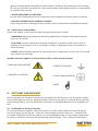
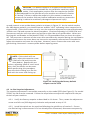
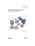
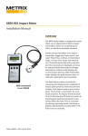
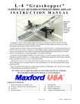
1
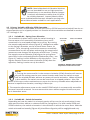
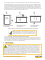
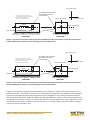
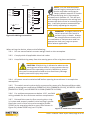
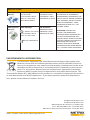
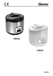
5550 & 5550G MECHANICAL VIBRATION SWITCHES
User Guide / Installation Manual
MODEL 5550
1180
The 5550 and 5550G mechanical vibration
switches provide vibration protection for
low- to medium-speed machinery. An inertia
sensitive mechanism activates a snap-action
switch with SPDT output contacts if the vibration exceeds an adjustable setpoint. The
5550 mechanical vibration switch contacts
can be used to activate an alarm or initiate
equipment shutdown. The housing is weatherproof with an optional hazardous area
rating. Electrical (remote) reset with start-up
time delay and a second set of SPDT output
contacts to accommodate DPDT needs
(e.g. separate trip and trip light circuits) are
available.
The 5550G uses identical internal mechanisms, but carries an IECEX rating ideal for
IIC gas group applications.
MODEL 5550G
1180
DOC# 1231558 • REV B (Oct 2014)
NOTE: The 5550/5550G
switches must be stored in a dry
area when not installed. The
included cap plug protects the
conduit hole thread from damages during shipping/handling
and potential debris/dust from
entering the housing.
1. PRINCIPLES OF OPERATION
1.1 Overview
Model 5550 and 5550G Mechanical Vibration Switches offer basic protection against gross
changes in structural seismic acceleration. The two units are identical internally and differ
only in their enclosure style and external access to adjustments. The 5550G is used for hazardous area applications requiring gas group IIC approvals, but has no externally accessible
adjustments. The 5550 has externally available setpoint adjustment and reset facilities, and
can be used for applications up to gas group IIB + hydrogen. Refer to hazardous area installation manuals M8905 (model 5550) and 100356 (model 5550G) for additional information.
The operating mechanism is purely mechanical and
consists of a tension spring attached to a pivoting
plate on an over-center fulcrum – magnets are not
employed. Normally, this plate is in an untripped
position (Figure 1A). However, in the presence of
sufficient seismic acceleration (whether vibratory
or impact), the trip plate will pivot beyond this
over-center position, snapping to a stable tripped
position (Figure 1B) where it contacts an internal
Figure 1A: 5550 mechanical switch trip
micro-switch relay, changing the state of the relay. mechanism in untripped position. Microswitch (red) is not actuated.
This relay is available for external wiring connections where on/off changes in electrical continuity
can be used to trip the machine and/or annunciate excessive vibration.
After the switch assumes its tripped position, it
must be reset manually by means of the external
reset plunger (5550 only), or by means of a remote
electrical reset (standard on 5550G, optional on
5550). The remote reset capability can also be
used as a startup delay to hold the switch in an
Figure 1B: 5550 mechanical switch trip
untripped state for as long as coil excitation is sup- mechanism in tripped position. Microplied – up to 30 seconds (the maximum duration
switch (red) is actuated.
is governed by a non-adjustable, factory-installed
thermistor circuit). The startup delay feature is useful during machinery startup when vibration in excess of the normal trip setting may be temporarily incurred.
1.2 Typical Application
The model 5550 and 5550G mechanical vibration switches are typically used on cooling
tower fans and mounted such that loss of a blade will result in significant structural acceleration at the switch mounting location (Figure 2).
The switch may be used on other types of machinery as well, but care must be taken to ensure that
adequate change in acceleration between “normal”
and “malfunction” conditions will exist at the switch’s
mounting location. The switch is not designed to reliably trip for acceleration levels below approximately
1 g (9.8 m/s2), or when less than 1 g exists between
a machine’s normal running vibration levels and malfunction vibration levels.
Doc# 1231558 • REV B (Oct 2014) Page 2 of 20
Figure 2: Typical 5550 installation on
cooling tower fan support strut.
NOTE: Metrix Mechanical Vibration Switches
are not intended for use on high-speed turbomachinery or on machines where changes
in seismic acceleration smaller than 1G must
be reliably detected. Instead, Metrix offers
more sophisticated electronic vibration sensing solutions that are better suited for such applications.
1.3 Primary Variables Affecting 5550 Operation
The required seismic acceleration to move the 5550 or 5550G mechanical switch from its untripped position to its tripped position is a function of three variables as detailed in sections
1.3.1 through 1.3.4.
1.3.1 Variable #1 – Spring Force Direction
SETPOINT
The movable trip plate mass inside the switch housing is
ADJUST
free to move on an essentially frictionless pivot, and is
restrained in its untripped position by a spring. By turning
the setpoint adjustment screw (Figure 3), changes are made
to the spring’s direction, and to a much lesser extent, its
tension. Thus, the spring mechanism exerts an essentially
constant force on the trip plate and turning the setpoint adjustment screw changes the direction of this force. Turning
the setpoint screw clockwise (CW) aligns the spring force
more fully in the untripped direction (below the pivot – see
Figure 1), making it more difficult to trip the device. Turning the setpoint screw counter-clockwise (CCW) does the
opposite, making it easier to trip the device.
RESET PLUNGER
FIGURE 3: MODEL 5550 setpoint
adjustment and manual reset.
NOTES:
1. Turning the screw too far in the counter clockwise (CCW) direction will eventually pull the spring past the over-center location and cause the switch to snap
into the tripped position without any external inertial excitation. When adjusted
in this manner, the switch cannot be reset from its tripped position. Also, the
nature of this over-center mechanism can cause it to be very unstable when adjusted too
close to its equilibrium location, resulting in false trips.
2. The setpoint adjustment screw on the model 5550G switch is not externally accessible.
The cover must be removed. Do not remove the cover while energized circuits are present in hazardous areas
1.3.2 Variable #2 – Switch Orientation
Depending on how the switch is oriented, gravity will act on the trip mechanism’s movable mass to either add to or subtract from the spring force. For both model 5550 and
5550G switches, the switch orientation is the direction in which the cover faces. With the
switch oriented horizontally (Figure 4A), the effects of gravity will be negligible and only
Doc# 1231558 • REV B (Oct 2014) Page 3 of 20
SENSITIVE
AXIS
SENSITIVE
AXIS
4A: Horizontal orientation,
cover facing right
4B: Vertical orientation,
cover facing up
GRAVITY
SENSITIVE
AXIS
GRAVITY
GRAVITY
the spring force will govern the trip plate’s behavior. With the switch oriented vertically
up (Figure 4B), gravity acts to keep the trip plate’s movable mass in the untripped position,
and inertial excitation must counteract both gravity and the spring force. With the switch
oriented vertically down (Figure 4C), gravity acts in the opposite direction and opposes the
spring’s force. Thus, with the same setpoint adjustment, a switch facing up will require the
most excitation to trip, a switch facing horizontally will require 1g less excitation to trip, and
a switch facing down will require 2g less excitation to trip.
4C: Vertical orientation,
cover facing down
FIGURE 4: Side views showing horizontal and vertical orientations of 5550 switch
NOTE: Depending on how the setpoint is adjusted, simply turning the switch on its side or upside down may be
sufficient to cause it to trip, due to the effects of gravity.
1.3.3 Variable #3 – Vibration Forces Acting on the Switch
By shaking or impacting the switch along its sensitive axis with sufficient inertial force for
a sufficient duration and within its frequency response range, the trip plate mechanism
will overcome the combined forces of gravity (depending on orientation) and spring tension, snapping from untripped to tripped position.
2. INSTALLATION
WARNING: Before proceeding to install model 5550 and 5550G switches, read
and thoroughly understand these instructions. They are intended for experienced personnel who require only basic installation guidance, and assume that
the switch has already been selected and applied properly for the machinery at hand.
When installing the switches in hazardous atmospheres, refer to Metrix manuals M8905
(5550) and 100356 (5550G) for important safety information. All of these manuals, as
well as additional technical resources, are available on our website at www.metrixvibration.com. You may also contact Metrix or its local representative for additional assistance,
using the information on the last page of this manual.
Doc# 1231558 • REV B (Oct 2014) Page 4 of 20
2.1 Maintenance Convenience Versus Measurement Quality
While it is desirable to mount the switch in a location in which it can be easily serviced and
maintained, this should not be the dominant consideration. The switch serves as a mechanical sensor and for it to provide suitable machinery protection, it must be mounted in a
location and orientation where the machine’s inertial forces during malfunction conditions
will be suitably large to trip the switch. Thus, locating the switch for optimal mechanical
sensing – rather than optimal serviceability – must always remain the primary consideration.
However, in most circumstances, judicious choice of mounting location and switch orientation can accommodate both requirements satisfactorily.
2.2 Sensitive Axis
The switch is designed to respond to inertial forces only in the direction of its sensitive axis
(Figure 4). When care is not taken to mount the switch properly, relatively large inertial
forces can occur elsewhere on the machine that will not be transmitted properly to the
switch, and/or will occur in a direction perpendicular to the switch’s sensitive axis. Both of
these conditions can render the switch’s ability to trip less effective or even ineffective.
2.3 Horizontal Orientation
A horizontal orientation of the switch means that it is mounted with its sensitive axis perpendicular to the direction of gravity (refer to Figure 4A). In this orientation, the effects of
gravity on the switch’s trip mechanism are negligible and the trip point is governed almost
entirely by the spring. It is recommended that the switch be oriented horizontally because
most machines are less constrained (less stiff) in the horizontal direction than in the vertical
direction and will therefore vibrate more in the horizontal direction.
2.4 Vertical Orientation
A vertical orientation of the switch means that it is mounted with its sensitive axis parallel to
the direction of gravity. It is not recommended that the switch be oriented vertically (except
as noted above) because most machines are more constrained (more stiff) in the vertical direction than in the horizontal direction, and will therefore vibrate less in the vertical direction.
NOTE: When specifying units with 2g reset coil holding
strength simultaneously with a 24 VDC reset coil, do not install
the switch with a horizontal orientation or upside down. The
reset coil lacks sufficient holding force for anything other than
a vertical “face up” orientation (Figure 4B).
2.5 Horizontal Machines
Although Figures 5 and 6 both show horizontal switch orientations, they are not equivalent.
In Figure 5, the sensitive axis of the switch points directly at the machine’s shaft; in Figure
6, it does not and instead is aimed at point P somewhere above the shaft. Either mounting
orientation can be effective, but 5 is preferred.
Doc# 1231558 • REV B (Oct 2014) Page 5 of 20
Shaft Radial Y Axis
NOTE: A drain hole at low point is
recommended to allow accumulated
moisture to exit (except in
explosion-proof installations)
5550 MOUNTING LOCATION
WITH CONDUIT FITTING
FACING DOWN
SHAFT CENTERLINE
SHAFT Z AXIS
(AXIAL)
Shaft Radial X Axis
SHAFT CENTERLINE
CONDUIT
BASEPLATE
CONDUIT
SIDE VIEW
END VIEW
Figure 5: Horizontal machine showing horizontal 5550 mounting orientation and preferred location.
Conduit fitting faces down to allow drainage of any condensation.
Shaft Radial Y Axis
NOTE: A drain hole at low point is
recommended to allow accumulated
moisture to exit (except in
explosion-proof installations)
5550 MOUNTING LOCATION
WITH CONDUIT FITTING
FACING DOWN
SHAFT CENTERLINE
SHAFT Z AXIS
(AXIAL)
P
Shaft Radial X Axis
SHAFT CENTERLINE
CONDUIT
BASEPLATE
CONDUIT
SIDE VIEW
END VIEW
Figure 6: Horizontal machine showing horizontal 5550 mounting orientation and alternate location.
Conduit fitting faces down to allow drainage of any condensation.
Figure 7 shows the same horizontal machine as in Figures 5 and 6, but with the switch oriented vertically. As noted in Section 2.4, a vertical orientation of the switch is discouraged
because machines will generally experience less vibration in the vertical direction than in
the horizontal direction, and the switch will be less effective. Metrix does not recommend
installation as shown in Figure 7 unless the machine truly experiences more vibration in the
vertical direction than in the horizontal direction, or the 2g / 24V reset coil option is being
used (see note in Section 2.4).
Doc# 1231558 • REV B (Oct 2014) Page 6 of 20
Shaft Radial Y Axis
5550 MOUNTING LOCATION
SHAFT CENTERLINE
Shaft Radial X Axis
SHAFT Z AXIS
(AXIAL)
SHAFT CENTERLINE
CONDUIT
BASEPLATE
SIDE VIEW
END VIEW
Figure 7: Horizontal machine showing vertictal 5550 mounting orientation (not recommended).
2.6 Vertical Machines
Figure 8 shows the preferred installation for a vertical machine. The switch is mounted
horizontally and with its sensitive axis pointing directly at the shaft.
In contrast, Figure 7 shows the switch mounted vertically, which is not recommended.
Because most vertical machines (like horizontal machines) are rigidly fixed by a baseplate
or other mounting that constrains them from vibrating in the vertical direction, aligning the
switch’s sensitive axis in the vertical direction aligns it in the direction of least vibration.
Instead, mount the switch as shown in Figure 5 to ensure that radial (not axial) vibration is
detected. Mount the switch as shown in Figure 7 only when the machine actually vibrates
more in the vertical than horizontal direction, or when the 2 g /24 V reset coil option is used
(see note in section 2.4).
TOP VIEW
SHAFT CENTERLINE
BASEPLATE
CONDUIT
5550 MOUNTING LOCATION
WITH CONDUIT FITTING
FACING DOWN
SIDE VIEW
SHAFT Z AXIS
(AXIAL)
NOTE: A drain hole at low point is
recommended to allow accumulated
moisture to exit (except in
explosion-proof installations)
Shaft Radial Y Axis
CONDUIT
BASEPLATE
Shaft Radial X Axis
Figure 8: Vertical Machine showing horizontal 5550 mounting orientation and recommended location
Doc# 1231558 • REV B (Oct 2014) Page 7 of 20
2.7 Mounting Rotation
The switch can be rotated about its sensitive axis without affecting its operation (Figure 9).
Thus, positions 9A, 9B, 9C, and 9D showing the model 5550 switch rotated at 12:00, 3:00,
6:00, and 9:00 positions respectively do not affect the operation of the switch and are primarily a matter of preference and serviceability. However, when possible, it is recommended that conduit fittings be oriented facing down, helping to prevent moisture or condensation accumulation inside the device.
9C - 6:00 horizontal orientation
9B - 3:00 horizontal orientation
9D - 9:00 horizontal orientation (preferred)
GRAVITY
9A - 12:00 horizontal orientation
Figure 9: Horizontal orientations of 5550. 9D position is strongly recommended
(conduit hole facing down) to allow drainage of any accumulated condensation.
2.8 Affixing The Switch To The Machine
Mount the switch securely to the machine using the 4-hole pattern (5550) or 2-hole pattern
(5550G) on the baseplate. It is extremely important that the device be rigidly attached
to the machine so that it reflects machinery vibration – not vibration incurred by a loose
mounting, an insufficiently stiff mounting bracket, or a bracket resonance. Also, the switch
should be mounted in a location where its own mass does not appreciably affect the natural
frequency(ies) of the member to which it is attached. When attaching to a support beam,
skid, or other member, thought should be given to the usefulness of the measurement and
what level of machinery damage must be present before sufficient acceleration will occur at
the measurement location. For additional application assistance, consult the factory or your
nearest Metrix representative.
2.9 Wiring
The switch provides a single SPDT relay or optional double SPDT relays, allowing use as a
DPDT device. When a reset / startup delay coil is specified (optional on 5550; standard on
5550G), suitable wiring terminals are also available. Refer to Figure 10 for wiring terminal
assignments.
Doc# 1231558 • REV B (Oct 2014) Page 8 of 20
WIRING DIAGRAM
SPDT
NOTE: It is not recommended
that wiring be connected to the
device until after verifying the
factory default setpoint in Section
4.1 and performing the in-situ setpoint
adjustments in Section 4.2. This will prevent having to disconnect the wiring and
remove the device from its mounting location. It will also prevent unwanted trips
while initially adjusting the setpoint.
DPDT
NOM
OPEN
NOM
OPEN
COM
COM
NOM
CLOSED
NOM
CLOSED
NOM
OPEN
COM
NOM
CLOSED
L(+)
RESET COIL
L(+)
RESET COIL
CASE
CASE
GRN
N(-)
GRN
RESET COIL
N(-)
DPDT CONTACTS AND RESET COIL OPTION
Figure 10: Wiring connections
RESET COIL
WARNING: Voltages present at
switch terminals can result in
serious injury or death. Always
de-energize these circuits prior
to installation or maintenance and use
appropriate lock-out / tag-out procedures where applicable.
When wiring the device, observe the following:
2.9.1 Do not exceed switch contact ratings listed on the nameplate.
2.9.2 Comply with all applicable electrical codes.
2.9.3 Keep field wiring away from the moving parts of the trip plate mechanism.
CAUTION: If field wiring is allowed to obstruct the
moving parts of the switch, it may prevent the trip
plate from operating correctly. Machinery protection can be compromised and serious machinery damage
and/or personnel injury may result.
2.9.4 All power must be switched off before opening the enclosure in an explosive
atmosphere.
2.9.5 The switch must be electrically connected by means of a flameproof/dust cable
gland or stopping box certified to IEC60079-0:2011 (EN60079-0:2012), IEC60079-1:2007
(EN60079-1:2007), and IEC600079-31:2008 (EN60079-31:2009).
2.9.6 For ambient temperatures below -10°C, use field
wiring suitable for the minimum ambient temperature.
2.9.7 Reinstall the cover by first ensuring the o-ring
is in place and properly seated in the housing’s groove.
Place the cover on the unit and screw tight (model
5550G) or by torqueing the four cover bolts shown in
Figure 11 (model 5550 only) to 6-7 ft/lbs.
4
1
2
3
Figure 11: 5550 cover bolt locations
Doc# 1231558 • REV B (Oct 2014) Page 9 of 20
NOTE: Do not over-torque the cover bolts on the model 5550
switch. This could damage the housing and compromise the seal.
2.10Conduit: When attaching conduit, observe the following:
2.10.1 Avoid long runs of unsupported conduit that can transfer unwanted impacts or
vibration of the conduit, rather than of the machine.
2.10.2 Always slope conduit away from the switch and generally orient such that accumulated moisture or condensation does not drain into the switch. For non-explosion proof
installations, consider the use of an adequate number of J-traps or other drain mechanisms at low points to preclude moisture from collecting in the switch or in the conduit.
When possible, mount the switch so that the conduit outlet faces down.
2.10.3 Units with NPT conduit holes (ordering option E=1, 2, 3, 7) have ¾” NPT threads.
Units with metric conduit holes (ordering option E=4, 6, and 8) have M20 x 1.5 threads.
Refer to Metrix datasheet # 1004461 for a complete list of ordering options.
2.10.4 Use proper conduit seals and hole plugs meeting the environmental requirements
of the installation to prevent ingress of moisture and dust.
NOTE: The disposable plastic plugs (caps) that ship in each
conduit hole provide only physical thread protection during shipping and handling. They are not designed for use
as permanent hole plugs and do not provide adequate environmental protection for the switch when installed in the field.
2.11Protecting Against Moisture Ingression
All installations should observe the guidelines of 2.10. These are particularly important
when the switch will be mounted in moist environments such as on cooling tower structures, evaporative fans, marine applications, or other installations where the switch will be
exposed to rain, elevated humidity, hose-directed water, or any environmental conditions
that might allow condensation to form at or in the switch, associated wiring, and conduit.
2.11.1 Ensure the cover is properly tightened
The importance or properly tightening cover bolts (5550) or screw-type lid (5550G) pertains not just to sealing against ignition of a flammable atmosphere outside the switch,
but also to prevent dust or moisture ingression to the switch internals.
2.11.2 Examine Cable Insulation for Nicks and Cuts
In some cases, properly rated cable may be installed without solid or flexible conduit to
CAUTION: Do not over or under-torque housing screws.
Over torqueing can damage the housing and compromise the seal. Under torqueing can permit moisture to
weep into the switch. Either condition can compromise switch
operation and/or present an electrical shock hazard.
Doc# 1231558 • REV B (Oct 2014) Page 10 of 20
preclude it as a potential source of moisture collection. However, whether installed with
or without conduit, all cables should be examined for nicks and cuts that compromise the
protective outer jacketing. In particular, multi-conductor cables can act as very effective
wicks when the outer jacket has been cut or damaged. Once moisture ingresses into the
cable, it will often find its way into the switch via this wicking mechanism, even when an
appropriate gland seal is used at the switch’s conduit opening and the outer periphery of
the cable is not leaking at the gland.
2.11.3 Liberally Apply Silicone Dielectric Grease to all Openings
The primary points of moisture entry into the switch are where the housing is penetrated:
- The setpoint adjustment screw (5550 only)
- The reset plunger (5550 only)
- The conduit fitting(s)
- The seal between housing body and housing cover
O-ring seals and gaskets are used at each of these entry points and silicone dielectric
grease is applied at the factory. However, in extremely moist environments an additional
liberal coating of silicone dielectric grease should be applied in the field at time of
installation. This practice will provide added protection against moisture ingression
over time. Metrix recommends Dow Corning #33 Molykote® Extreme Low Temperature
Silicone Grease or equivalent.
2.12Outline Diagrams and Physical Dimensions
Refer to the Metrix product datasheet # 1004461, available at www.metrixvibration.com
3. IMPORTANT SAFETY INFORMATION
3.1 General Safety Summary
Review the following safety precautions to avoid injury and prevent damage to this product
or any products connected to it.
• USE ONLY AS SPECIFIED
To avoid potential hazards, use this product only as specified. Only qualified personnel
should perform installation and removal procedures.
• CONNECT AND DISCONNECT PROPERLY
Do not connect or disconnect this product while it is connected to a live power source.
• GROUND THE PRODUCT
The housing of this product should be connected to earth ground. Before energizing the
product, ensure its housing is properly grounded.
• OBSERVE ALL TERMINAL RATINGS
To avoid fire or shock hazard, observe all ratings and markings on the product. Consult
the individual sections of this manual for further information before making connections
to the product.
• DO NOT OPERATE WITHOUT COVER
The cover serves multiple purposes that may include protection against moisture and
dust ingression, protection of personnel from electrical shock, and protection against
Doc# 1231558 • REV B (Oct 2014) Page 11 of 20
ignition of flammable atmospheres when used in locations with hazardous area ratings.
Do not use the device without its cover except when making adjustments or connections
as noted in this manual.
• AVOID EXPOSURE TO CIRCUITRY
Do not touch exposed electrical connections and components when power is present.
• DO NOT OPERATE WITH SUSPECT FAILURES
If you suspect there is damage to this product, have it inspected by qualified personnel.
3.2 Safety Terms and Symbols
Terms that appear in this manual requiring special attention include:
• WARNING: Warning statements identify conditions or practices that could result in
injury or loss of life.
• CAUTION: Caution statements identify conditions or practices that could result in
damage to the product, loss or corruption of data, or damage to the environment or
other property.
• NOTE: Notes identify material of special interest or importance to the user, not including cautions or warnings.
Symbols that may appear on the product and/or in this manual include:
• HIGH VOLTAGE PRESENT
• DANGER or CAUTION
• PROTECTIVE EARTH
• FUNCTIONAL GROUND
• NOTE
4. SETPOINT ADJUSTMENT
Metrix mechanical vibration switches are shipped from the factory such that when slowly
rotated 180 degrees from an upright position (cover facing up) to an upside down position
(cover facing down), the trip plate will snap from its untripped position to its tripped position.
4.1 Verification of Factory Setpoint
To verify the factory setpoint, place the switch on a flat surface with the cover facing up.
Do not connect any wiring yet. Press the reset plunger (model 5550 only – remove cover
on model 5550G) to ensure the switch is in its untripped position (it may have tripped due
to shock or vibration incurred during shipping and handling). Then, slowly lift the switch
Doc# 1231558 • REV B (Oct 2014) Page 12 of 20
CAUTION: The default setpoint as shipped from the factory is
not intended to be suitable for any particular machinery application. Each application requires that the setpoint be carefully field adjusted for the specifics of your machine as outlined in Section
4.2 below. Failure to adjust the setpoint in this manner constitutes a
misuse of the product and may lead to ineffective machinery protection
resulting in extensive machinery damage and personnel injury.
up and rotate it to an upside down position as shown in Figure 12. As the switch reaches
the 180-degree position, you should hear an audible “click” indicating it has snapped to its
tripped state. If the device does not trip, turn the setpoint adjustment screw approximately
1/16th turn CCW and repeat the above procedure. Continue adjusting in 1/16th CCW turn
increments until the unit trips when turned from right side up to upside down. When performing this verification on the Model 5550G, it is recommended that you leave the cover
off. The presence or absence of the cover does not affect the setpoint during the verification
process and ensures the cover does not have to be repeatedly removed and reinstalled to
adjust the setpoint and reset the trip plate. However, never remove the cover with energized wiring connected – remove power before opening cover.
NOTE: If the switch will not
reset, adjust the setpoint screw
1/8th turn CW and press the
reset button. Repeat this procedure, adjusting 1/8th of a turn each
time, until the device can be reset.
While performing this procedure,
keep the device sitting on a flat surface with the cover side facing up.
Figure 12: Verifying the factory default
setpoint on the 5550
4.2 In-Situ Setpoint Adjustment
The setpoint adjustment is accessible externally on the model 5550 (see Figure 3). For model
5550G, the lid must be removed. Follow the steps below to adjust the setpoint for the particulars of your machine.
4.2.1 Verify the factory setpoint as described in 4.1 above. Then, rotate the adjustment
screw one full turn (360 degrees) clockwise and proceed to step 4.2.2.
4.2.2 Install the switch on the machine following the guidelines of section 3. Ensure
the field wiring is disconnected. If it has already been connected, disconnect temporarily,
Doc# 1231558 • REV B (Oct 2014) Page 13 of 20
taking appropriate cautions around any wiring that is (or may become) energized during
machine starting sequences and the setpoint adjustment procedure.
4.2.3 Reset the switch by depressing the reset plunger (5550) or manually pushing the
exposed trip plate into its untripped position (5550G).
4.2.4 Connect a continuity tester or ohmmeter across COM & NOM OPEN terminals
(refer to Figure 10). This will allow you to visually confirm when the normally open relay
contacts close, indicating the switch has tripped. This is also true for COM & NOM CLOSE,
the normally closed relays contacts open when tripped.
NOTE: This step accomplishes two objectives. First, it allows the installer to easily ascertain when the switch has snapped from its untripped state to its tripped state, as it may be difficult or impossible
to listen for an audible “click” in the presence of ambient machine noise.
Second, it allows appropriate setpoint adjustments to be made without
unnecessary trips of the machine (repeated starts/stops on a machine are
usually undesirable and may be electrically and/or mechanically damaging
in some circumstances).
4.2.5 Hold the reset plunger (5550) or trip plate (5550G) down and start the machine.
When the machine has reached running speed, release the plunger (5550) or trip plate
(5550G).
4.2.6 If the switch trips when releasing the plunger/trip plate, rotate the setpoint screw
a full turn (360 degrees) CW and then depress the plunger/trip plate, holding it in the
untripped position. Release the plunger/trip plate once again and watch to see if the
switch trips. Repeat this process until the switch does not trip with the machine running
at normal operating speed. Then, proceed to step 4.2.7.
4.2.7 With the machine running, SLOWLY turn the setpoint adjustment screw CCW in
1/8th turn increments until the switch trips. Then, turn the screw in the opposite direction (CW) 1/8th turn and reset the switch.
4.2.8 Allow the machine to run for as long as necessary to ensure the switch does not
trip under normal speed, load, and other operating condition changes. If the switch does
not trip, proceed to step 4.2.10. If it trips, proceed to step 4.2.9.
4.2.9 (Perform this step only if the switch tripped in step 4.2.8.) Turn the setpoint
adjustment screw in the CW direction (increasing setpoint) in the smallest increment possible – preferably 1/16th turn or less. Reset the switch and repeat step 4.2.8.
NOTE: The objective is to establish a setpoint as close as possible to
normal operating conditions, while still allowing normal fluctuations
in speed, load, flow, etc. without false trips. Establishing a setpoint
that is too high may render machinery protection ineffective. DO NOT at
this time attempt to adjust the setpoint for high vibration encountered
during machine startup. This will be addressed in step 4.2.11.
Doc# 1231558 • REV B (Oct 2014) Page 14 of 20
NOTE: If more than one full turn of the setpoint screw is required to accommodate variations in normal running conditions
without false trips, the 5550 may not be an appropriate device
for your application. Contact the factory for assistance.
4.2.10 You have now established your unique setpoint and no further adjustment is
required. If the switch was supplied with an optional reset / startup delay coil, connect all
field wiring and proceed to section 5. If the switch was not supplied with this coil, proceed
to step 4.2.11 to determine whether a startup delay is needed for your application.
4.2.11 Stop the machine, press the reset plunger pushbutton to ensure the switch is in its
untripped state, and then restart the machine. If the switch does not trip during machine
startup, you do not require a startup delay. Connect all field wiring and place the switch
into service. If it does trip due to elevated vibration levels during startup, you will require
an appropriate startup delay coil (see section 5). Consult the factory or your nearest
Metrix representative for assistance.
CAUTION: The switch’s setpoint must be established relative
to normal machinery operation, not startup vibration levels.
DO NOT adjust the setpoint screw to increase the switch’s
trip point if the machine trips due to high vibration during startup.
The startup delay feature (optional on 5550 – standard on 5550G) is
specifically designed to suppress the switch from tripping for a pre-set
interval during startup. Elevating the setpoint to accommodate startup vibration levels can result in missed trips during genuine machinery
malfunction conditions, and constitutes a misuse of the switch.
5. ELECTRICAL RESET AND STARTUP DELAY
When a reset coil is specified (standard on 5550G, optional on 5550 where ordering option D
= 1, 2, 3, or 4), an electrical solenoid mechanism is installed that allows remote reset of the
switch when in its tripped position, and initiation of a startup delay when in its untripped
position. To activate these features, the rated voltage must be applied to the reset coil wiring terminals (refer to Figure 10). The reset function requires only momentary application of
voltage. The startup delay function requires continuous application of voltage for the duration of the factory pre-set time delay (approximately 20-30 seconds).
5.1 Electrical (Remote) Reset
This feature allows remote reset of the switch from its tripped position. To activate,
momentarily apply the rated voltage across the appropriate terminals (refer to Figure 10),
taking care to observe the polarity. The application of this voltage will energize the solenoid
mechanism, extending its plunger and resetting the switch to its untripped position. Once
the solenoid has reset the switch, voltage can be removed. The switch will remain in its
untripped position until sufficient acceleration trips it.
5.1.1 Continuous Bypass
It is not possible to continuously bypass the switch using the reset function. A continuous voltage across the reset terminals will activate the startup delay feature lasting
approximately 20-30 seconds, after which the switch will return to normal operation. If a
continuous bypass function is required, an isolation switch should be installed in the same
Doc# 1231558 • REV B (Oct 2014) Page 15 of 20
circuit as the output relay(s), allowing the 5550/5550G to be removed from the machinery
shutdown loop.
NOTE: The reset coil circuit contains a thermistor that allows the circuit to
also function as a startup delay when voltage is continuously applied (see
section 5.2). If the thermistor is hot, current will not flow and the reset
function will not operate. A cool-down period may be required (see Section
5.2.1). In many applications, voltage is continuously applied to the reset coil terminals while the machine is running. In such situations, the thermistor will still be
hot immediately following a trip and it will not be possible to electrically reset the
switch until the thermistor has cooled sufficiently. If necessary, the switch can be
manually reset (5550 only), using the plunger pushbutton to allow a “hot” restart.
Alternatively, it may be desirable to program the machine’s control system to apply voltage to the reset coil for only 30 -40 seconds during machine start up. This
practice ensures that the thermistor is more likely to be “cold” following a trip,
allowing an immediate remote reset.
5.2 Startup Delay
The startup delay feature is intended for use in machines that exhibit high vibration during
startup. This feature maintains the switch in an untripped position for a factory pre-set
delay period of approximately 30 seconds, after which the switch resumes normal operation.
To activate startup delay, continuously apply the specified voltage across the reset terminals
and the switch will be suppressed from tripping for the preset delay period, allowing the
machine to run up to operating speed and normal vibration levels. Voltage must be continuously applied for the duration of the startup delay (approximately 30 seconds). If this voltage is removed prematurely, the coil will de-energize and the switch will not be suppressed
from tripping.
WARNING: Voltages present at reset terminals can result
in serious injury or death. Always de-energize these
circuits prior to installation or maintenance and use appropriate lock-out / tag-out procedures where applicable. 5.2.1 Thermistor Considerations
The startup delay feature works through use of an internal thermistor in series with a solenoid mechanism. When voltage is continuously applied, current flows in the circuit and the
thermistor’s temperature rises, gradually restricting current flow. When the current drops
below the minimum value required to keep the coil energized, the solenoid retracts. Normally, it takes approximately 30 seconds for the thermistor to reach this “cut-off” temperature. However, several factors can serve to shorten or lengthen this interval as follows:
• Ambient Temperature Effects
The time for the thermistor to reach its cut-off value depends on the initial temperature of the thermistor. If the switch is at an ambient temperature of -30C during the winter months, it will exhibit a longer startup delay than during the summer
months when ambient temperatures may be 30C. Likewise, if the switch is placed
on a machine that can sustain a large temperature rise at the mounting location,
the switch may be near its maximum temperature rating of 70C after a period of
prolonged operation. This will shorten the startup delay interval when compared to
operation on a “cold” machine.
Doc# 1231558 • REV B (Oct 2014) Page 16 of 20
•
Cool-Down Period
If the circuit activating the startup delay leaves the voltage continuously applied (as
is typical), the thermistor will remain hot until voltage is removed, such as following a machine trip. Thus, when the thermistor is not allowed to cool to its ambient
surroundings, it will shorten the startup delay.
•
Immediate Restart
If a restart is required immediately following a trip, the thermistor may be so hot
that the switch cannot be immediately reset using the remote reset function. In
such situations, it will be necessary to either manually reset the switch or wait for
the thermistor to cool sufficiently. Alternatively, it may be desirable to modify the
machinery control logic such that voltage is only applied to the reset terminals for
the duration of the factory pre-set delay, ensuring that the thermistor circuit is only
energized at startup.
•
Current Flow
The amount of current flowing through the thermistor will be a function of the voltage applied, the thermistor’s resistance, and the resistance elsewhere in the circuit.
Loose, intermittent, or corroded wiring connections can increase resistance and result
in a longer startup delay interval. If the resistance is too great, the reset coil will not
energize at all due to insufficient current. Insufficient voltage and/or current can also
be a problem. Be certain that the coil voltage rating (ordering option D) matches the
voltage and current your circuit supplies. See Table 1 on the following page.
Option D
(coil voltage)
Option C
(coil holding
force)
Rated
Voltage
Min
Voltage
Max
Voltage
Min
Current
Max Power
Consumption
None (D=0)
All
N/A
N/A
N/A
N/A
N/A
115 Vac (D=1)
All
115 Vac
103.5 Vac
126.5 Vac
1.24 A
287.5 W
230 Vac (D=2)
All
230 Vac
207 Vac
253 Vac
0.32 A
230 W
5 g (C=1)
24 Vdc
22.8 Vdc
25.3 Vdc
1.58 A
60 W
2 g (C=2)
24 Vdc
22.8 Vdc
25.3 Vdc
1.18 A
28.8 W
24 Vdc (D=3)
115 Vdc (D=4)
10 g (C=3)
24 Vdc
22.8 Vdc
25.3 Vdc
2.88 A
72 W
All
115 Vdc
103.5 Vdc
126.5 Vdc
1.20 A
207 W
Table 1: Reset / Startup Delay Coil Electrical Characteristics
5.3 Coil Considerations
5.3.1 Coil Hold Strength
The reset / startup delay coil is sized to provide a specified holding strength (option C), allowing the startup delay feature to hold the switch in its untripped state even in the presence of high vibration encountered during machine startup. If the reset coil supplied will
not hold the switch in an untripped state during startup, it may be the wrong size. Refer
to Table 1 and consult the factory for assistance.
Doc# 1231558 • REV B (Oct 2014) Page 17 of 20
5.3.2 Duration Considerations
The duration of the startup delay (approximately 30 seconds) is factory set and cannot
be altered. With the switch in an untripped state, continuous application of the specified
voltage to the reset terminals will initiate the delay feature, but will not cause it to persist.
That is, applying a continuous voltage across the reset terminals for longer than 20-30
seconds does not allow one to arbitrarily increase the duration of the startup delay. See
section 5.2.1 for a more in-depth explanation of the circuit operation.
NOTE: The 24 VDC reset coil comes in three different versions,
depending on the holding strength option specified (option C).
Although each has the same min/max voltage rating, the current
draw will be larger for larger holding coil strengths, as noted in Table 1. Be
certain your power source for this coil is capable of supplying the necessary current for the rated holding strength.
6. DRAWINGS, SPECIFICATIONS, AND ORDERING INFORMATION
Unless otherwise noted, all figures and illustrations in this manual depict the model 5550
mechanical switch. The 5550G is identical in terms of its internal mechanisms, but has a
different housing that is rated for use in the more stringent IIC gas group. For additional information on models 5550 and 5550G, including outline diagrams, Metrix specifications, and
ordering information, refer to Metrix product datasheet # 1004461. Refer also to hazardous
area installation manuals M8905 (5550) and 100356 (5550G) as appropriate.
Doc# 1231558 • REV B (Oct 2014) Page 18 of 20
7. HAZARDOUS AREA APPROVALS
MODEL 5550
IECEx Approval
(World):
IEC Markings:
Ex d IIB + H2 T6 Gb
Ex tb IIIC T85°C Db Ta -40°C to
+70°C IP66
IECEx BAS10.0020
IEC Standards:
IEC60079-0:2011
IEC600079-1:2007
IEC600079-31:2008
ATEX Approval
(Europe):
ATEX Markings:
EN Standards:
EN60079-0:2012
EN60079-1:2007
EN60079-31:2009
II 2GD Ex d IIB + H2 T6 Gb
Ex tb IIIC T85°C Db Ta -40°C to
+70°C IP66
1180
UL Approval
(North
America):
Baseefa 10ATEX0098
UL Markings:
Models 5550-2XX-XXX or
5550-7XX-XXXZ:
Class I, Div 1, Groups B,C,D,Class
II, Div 1,
Groups E,F,G, Type 4 or 4X, IP66
Models 5550-1XX-XXX or
5550-6XX-XXX:
Class I, Div 1, Groups C,D,Class
II, Div 1,
Groups E,F,G, Type 4 or 4X, IP66
UL/CSA Standards:
UL 698
UL 508
CSA C22.2 No. 25
CSA C22.2 No. 30
CSA C22.2 No. 14
CAUTION: TO REDUCE
RISK OF IGNITION OF
HAZARDOUS ATMOSPHERES, DISCONNECT
THE SUPPLY CIRCUIT
BEFORE OPENING. KEEP
ASSEMBLY TIGHTLY
CLOSED WHEN IN
OPERATION. CABLE
TEMPERATURE RISE 15K
- USE SUITABLE CABLE.
ATTENTION: AFIN
DE PREVENTIR
L-INFLAMMATION
D’ATMOSPHERES
DANGEREUSES COUPER
L’ALIMENTATION ELECTRIQUE CIRCUIT AVANT
D’OUVRIR COFFRET
GARDER LE COUVERCLE
BIEN FERMETANT QUE
LES CIRCUITS SONT
SOUS TENSION. TEMPERATURE DE CABLE
MONTE 15K - UTILISEZ
CABLE APPROPRIE.
Doc# 1231558 • REV B (Oct 2014) Page 19 of 20
MODEL 5550G
IECEx Approval IEC Markings:
(World):
Ex d IIC T6 Gb
Ex tb IIIC T85°C Db Ta
-40°C to +70°C IP66
IECEx BAS10.0095X
IEC Standards:
IEC60079-0:2011
IEC600079-1:2007
IEC600079-31:2008
ATEX Approval
(Europe):
EN Standards:
EN60079-0:2012
EN60079-1:2007
EN60079-31:2009
ATEX Markings:
II 2GD Ex d IIC T6 Gb
Ex tb IIIC T85°C Db Ta
-40°C to +70°C IP66
1180
Baseefa 10ATEX0177
CAUTION: TO REDUCE RISK
OF IGNITION OF HAZARDOUS
ATMOSPHERES, DISCONNECT THE
SUPPLY CIRCUIT BEFORE OPENING.
KEEP ASSEMBLY TIGHTLY CLOSED
WHEN IN OPERATION. CABLE
TEMPERATURE RISE 15K - USE
SUITABLE CABLE.
ATTENTION: AFIN DE PREVENTIR L-INFLAMMATION
D’ATMOSPHERES DANGEREUSES
COUPER L’ALIMENTATION ELECTRIQUE CIRCUIT AVANT D’OUVRIR
COFFRET GARDER LE COUVERCLE
BIEN FERMETANT QUE LES
CIRCUITS SONT SOUS TENSION.
TEMPERATURE DE CABLE MONTE
15K - UTILISEZ CABLE APPROPRIE.
ENVIRONMENTAL INFORMATION
This electronic equipment was manufactured according to high quality standards to ensure safe and reliable operation when used as intended. Due to its
nature, this equipment may contain small quantities of substances known to be
hazardous to the environment or to human health if released into the environment. For this reason, Waste Electrical and Electronic Equipment (commonly
known as WEEE) should never be disposed of in the public waste stream. The
“Crossed-Out Waste Bin” label affixed to this product is a reminder to dispose of this product
in accordance with local WEEE regulations. If you have questions about the disposal process, please contact Metrix Customer Service.
[email protected]
www.metrixvibration.com
8824 Fallbrook Dr. Houston, TX 77064, USA
Tel: 1.281.940.1802 • Fax: 1.713.559.9421
After Hours (CST) Technical Assistance: 1.713.452.9703
Doc# 1231558 • REV B (Oct 2014) Page 20 of 20