1
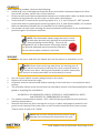
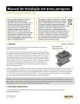
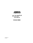
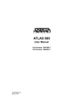
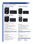
5550 & 5550G MECHANICAL VIBRATION SWITCHES
Hazardous Area Installation Manual
Before proceeding to wire and install the
Model 5550 switch, read and thoroughly
understand these instructions. They are
intended for experienced personnel who
require only basic installation guidance,
and assume that the 5550 has already
been selected and applied properly for
the machinery at hand. Please contact
Metrix or its local representative for
additional assistance. See also the “Supplamental Information” section of this
manual for additional technical resources
available free-of-change on our website
at www.metrixvibration.com
MODEL 5550
1180
OVERVIEW
The Model 5550 Mechanical Vibration
Switch offers basic protection against gross
changes in structural seismic acceleration.
Its operating mechanism is purely mechanical and consists of a tension spring attached
to a pivoting plate on an over-center
fulcrum – magnets are not employed.
Normally, this plate is in an untripped position. However, in the presence of sufficient
seismic acceleration (whether vibratory or
impact), the trip plate will pivot beyond this
over-center position, snapping to a stable
tripped position where it contacts an internal microswitch relay, changing the state
DOC# M8905 • REV N (Dec 2014)
MODEL 5550G
1180
of the relay. This relay is available for external wiring connections where on/off changes in
electrical continuity can be used to trip the machine and/or annunciate excessive vibration.
Once the switch has assumed its tripped position, it must be reset manually by means of the
external reset plunger, or by means of an optional remote electrical reset. The remote reset
capability can also be used as a startup delay to hold the switch in an untripped state for as
long as coil excitation is supplied – up to 30 seconds (the maximum duration is governed by
a non-adjustable, factory-installed thermistor circuit). The startup delay feature is useful
during machinery startup when vibration in excess of the normal trip setting may be temporarily incurred.
NOTE: The 5550 Mechanical Vibration Switch is not intended
for use on high-speed turbomachinery or on machines were
changes in seismic acceleration smaller than 1G must be
reliably detected. Instead, Metrix offers other electronic vibration
sensing solutions that are better suited for such applications.
SUPPLEMENTARY INFORMATION
Refer to product datasheet 1004461, and operation and maintenance manual 1231558 available at www.metrixvibration.com.
MOUNTING
Observe the switch nameplate to ensure that it has the correct hazardous approval and
environmental ratings for the intended area. Refer to Metrix datasheet 1004461 for a list of
all available hazardous area approvals, environmental ratings, and other ordering options.
See also the Hazardous Area Approvals section of this manual for hazardous area approvals
information.
The switch’s sensitive axis is in line with the reset plunger stem. Mount the switch solidly
to the machine’s frame such that this axis is aligned with the direction of expected vibratory
and/or impact motion. If the machine vibrates along multiple axes (and most machines do),
mount the switch to align with the direction of highest vibration. It is typical for machines
to vibrate more in the horizontal direction than in the vertical direction, as the foundation
normally constrains up-and-down motion more than side-to-side motion.
NOTE: Do not attempt to measure vibration or impact perpendicular
to the switch’s sensitive axis. The trip plate is free to move along
this axis only and will not respond to motion in other directions.
Doc# M8905 • REV N (December 2014) Page 2 of 8
CONDUIT
When attaching conduit, observe the following:
• Avoid long runs of unsupported conduit that can transfer unwanted impacts or vibration of the conduit, rather than of the machine.
• Orient conduit such that accumulated moisture or condensation does not drain into the
switch and consider the use of J-traps or other drain mechanisms.
• Units with NPT conduit holes (ordering option E=1, 2, 3, and 7) have ¾” NPT threads.
Units with metric conduit holes (ordering option E=4, 6, and 8) have M20 x 1.5 threads.
Refer to datasheet 1004461 for a complete list of ordering options.
• Use proper conduit seals meeting the environmental requirement of the installation to
prevent ingress of moisture and dust.
NOTE: The disposable plastic plugs that ship in each
conduit hole provide only physical thread protection
during shipping and handling. They are not
designed for use as permanent hole plugs and do
not provide adequate environmental protection
for the switch when installed in the field.
WIRING
•
Remove the cover and wire the switch (es) into the alarm or shutdown circuit.
NOTE: Route internal wiring away from the moving part of
the switch mechanism and secure so that it cannot move or
loosen over time. Wiring that impedes trip plate movement
may result in a switch that does not trip properly or at all.
•
•
•
•
•
•
Do not exceed switch contact ratings listed on the cover.
Observe all local electrical codes.
All power must be switched off before opening of the enclosure in an explosive atmosphere.
The Vibration Switch must be electrical connected by means of a flameproof/dust cable
gland or stopping box certified to:
IEC60079-0: 2011(EN60079-0:2012), IEC60079-1: 2007(EN60079-1:2007)
and IEC60079-31: 2008(EN60079-31:2009).
For ambient temperatures below –10°C, use field wiring suitable for the minimum
ambient temperature.
Reinstall the cover by first insuring the o-ring is in place and properly seated in the
grove in the housing. Place the cover on the unit and install the four cover screws.
Torque these screws to 6-7 ft/lbs.
NOTE: Do not over-torque the bolts as this could
damage the housing and compromise the seal.
Doc# M8905 • REV N (December 2014) Page 3 of 8
SETPOINT ADJUSTMENT
The setpoint is adjusted by means of a set screw, accessible on the switch’s cover. This set
screw makes very small changes to the angle of the internal tension spring, thereby increasing or decreasing the seismic acceleration level required to trip the device. The set screw
can be adjusted over a range of approximately 2 full turns (16 g’s peak); a 1/8th turn of this
set screw represents approximately 1g and is considered the smallest adjustment for which
repeatable results can be obtained. Turn the screw clockwise to increase the setpoint; turn
counter-clockwise to decrease the setpoint.
The switch orientation is defined as the direction in which the top of the reset plunger faces.
The switch ships from the factory with the setpoint at approximately 2g with the switch
oriented in the upward vertical position, and 1g when oriented in the horizontal position.
The factory default setpoint is not meant to be indicative of allowable vibration on any
particular machine or application. It is the responsibility of the user to determine the allowable vibration levels for their machine and adjust the setpoint accordingly. Refer to Metrix
5550 & 5550G User Guide / Installation Manual (doc 1231558) for additional step-by-step
guidance on establishing and adjusting the setpoint for your machinery. The manual can be
downloaded from www.metrixvibration.com.
NOTE: The setpoint is dependent on the switch’s physical orientation. A switch facing upward, downward, and horizontally will
trip at three distinctly different acceleration levels for the same
set screw adjustment. This is due to the force of gravity and how it will
either aid or oppose the relative ease of trip plate motion, depending
on switch orientation. For this reason, establish the desired setpoint
only when the switch is in its final mounted position.
REMOTE RESET AND STARTUP LOCKOUT
All Model 5550 Mechanical Switches can be reset locally using the manual reset plunger.
Additionally, those fitted with the optional electrical reset circuit can be remotely actuated.
The remote reset mechanism consists of an electrical solenoid in series with a thermistor. To
reset the switch remotely, apply the rated voltage (see nameplate) to the reset circuit terminals momentarily. This will energize the solenoid and push the trip plate from its tripped
position back to its untripped position.
Some machines exhibit elevated vibration during startup, above the established trip setpoint
for normal operation. To accommodate these situations, the same circuit may also be used
to provide a trip lockout during machine startup. Where vibration above the normal trip
setpoint may be present temporarily as the machine runs through and it would be otherwise impossible to start the machine without tripping. To use the startup lockout feature,
apply the rated voltage to the reset terminals continuously. This will energize the solenoid
continuously and keep the switch in its untripped position. The lockout will persist for 30
seconds, or as long as voltage is continuously applied, whichever is shorter (the thermistor in
this circuit which will automatically de-energize the solenoid after approximately 30 seconds
even if excitation voltage persists at the reset terminals). If the voltage is applied continuously rather than using an external timer or sequencer, please note that the voltage must be
removed from the reset circuit when the machine is stopped to allow the thermistor to cool
off. If this is not done, it will not be possible to reset the switch remotely.
Doc# M8905 • REV N (December 2014) Page 4 of 8
NOTE: If the machine is restarted immediately after a shutdown, the
lockout period will be shortened because the thermistor will be hot. An
increase in the ambient temperature will also shorten the lockout period.
IMPORTANT SAFETY INFORMATION
General Safety Summary
Review the following safety precautions to avoid injury and prevent damage to this product
or any products connected to it.
• USE ONLY AS SPECIFIED
To avoid potential hazards, use this product only as specified. Only qualified personnel
should perform installation and removal procedures.
• CONNECT AND DISCONNECT PROPERLY
Do not connect or disconnect this product while it is connected to a live power source.
• GROUND THE PRODUCT
The housing of this product should be connected to earth ground. Before energizing the
product, ensure its housing is properly grounded.
• OBSERVE ALL TERMINAL RATINGS
To avoid fire or shock hazard, observe all ratings and markings on the product. Consult
the individual sections of this manual for further information before making connections
to the product.
• DO NOT OPERATE WITHOUT COVER
The cover serves multiple purposes that may include protection against moisture and
dust ingression, protection of personnel from electrical shock, and protection against
ignition of flammable atmospheres when used in locations with hazardous area ratings.
Do not use the device without its cover except when making adjustments or connections
as noted in this manual.
• AVOID EXPOSURE TO CIRCUITRY
Do not touch exposed electrical connections and components when power is present.
• DO NOT OPERATE WITH SUSPECT FAILURES
If you suspect there is damage to this product, have it inspected by qualified personnel.
Doc# M8905 • REV N (December 2014) Page 5 of 8
HAZARDOUS AREA APPROVALS
MODEL 5550
IECEx Approval IEC Markings:
(World)
Ex d IIB + H2 T6 Gb
Ex tb IIIC T85°C Db Ta -40°C to
+70°C IP66
IECEx BAS10.0020
IEC Standards:
ATEX Approval
(Europe)
EN Standards:
ATEX Markings:
II 2GD Ex d IIB + H2 T6 Gb
Ex tb IIIC T85°C Db Ta -40°C to
+70°C IP66
1180
UL Approval
(North
America)
IEC60079-0:2011
IEC60079-1:2007
IEC60079-31:2008
EN60079-0:2012
EN60079-1:2007
EN60079-31:2009
Baseefa 10ATEX0098
UL Markings:
UL/CSA Standards:
Models 5550-2XX-XXX or
5550-7XX-XXX:
UL 508
UL 698
CSA C22.2 No. 14
CSA C22.2 No. 25
CSA C22.2 No. 30
Class I, Div 1, Groups B,C,D, Class
II, Div 1,
Groups E,F,G, Type 4 or 4X, IP66
Models 5550-1XX-XXX or
5550-6XX-XXX:
Class I, Div 1, Groups C,D, Class
II, Div 1,
Groups E,F,G, Type 4 or 4X, IP66
Doc# M8905 • REV N (December 2014) Page 6 of 8
CAUTION: TO
REDUCE RISK OF
IGNITION OF HAZARDOUS ATMOSPHERES, DISCONNECT THE SUPPLY
CIRCUIT BEFORE
OPENING. KEEP
ASSEMBLY TIGHTLY
CLOSED WHEN IN
OPERATION. CABLE
TEMPERATURE RISE
15K - USE SUITABLE
CABLE.
ATTENTION: AFIN
DE PREVENTIR
L-INFLAMMATION
D’ATMOSPHERES
DANGEREUSES COUPER
L’ALIMENTATION
ELECTRIQUE
CIRCUIT AVANT
D’OUVRIR COFFRET GARDER LE
COUVERCLE BIEN
FERMETANT QUE
LES CIRCUITS SONT
SOUS TONSION.
TEMPERATURE DE
CABLE MONTE 15K
- UTILISEZ CABLE
APPROPRIE
MODEL 5550G
IECEx Approval IEC Markings:
(World):
Ex d IIC T6 Gb
Ex tb IIIC T85°C Db Ta
-40°C to +70°C IP66
IECEx BAS10.0095X
IEC Standards:
IEC60079-0:2011
IEC600079-1:2007
IEC600079-31:2008
ATEX Approval
(Europe):
EN Standards:
EN60079-0:2012
EN60079-1:2007
EN60079-31:2009
ATEX Markings:
II 2GD Ex d IIC T6 Gb
Ex tb IIIC T85°C Db Ta
-40°C to +70°C IP66
1180
Baseefa 10ATEX0177
CAUTION: TO REDUCE RISK
OF IGNITION OF HAZARDOUS
ATMOSPHERES, DISCONNECT THE
SUPPLY CIRCUIT BEFORE OPENING.
KEEP ASSEMBLY TIGHTLY CLOSED
WHEN IN OPERATION. CABLE
TEMPERATURE RISE 15K - USE
SUITABLE CABLE.
ATTENTION: AFIN DE PREVENTIR L-INFLAMMATION
D’ATMOSPHERES DANGEREUSES
COUPER L’ALIMENTATION ELECTRIQUE CIRCUIT AVANT D’OUVRIR
COFFRET GARDER LE COUVERCLE
BIEN FERMETANT QUE LES
CIRCUITS SONT SOUS TENSION.
TEMPERATURE DE CABLE MONTE
15K - UTILISEZ CABLE APPROPRIE.
Doc# M8905 • REV N (December 2014) Page 7 of 8
ENVIRONMENTAL INFORMATION
This electronic equipment was manufactured according to high quality standards to ensure safe and reliable operation when used as intended. Due to its
nature, this equipment may contain small quantities of substances known to be
hazardous to the environment or to human health if released into the environment. For this reason, Waste Electrical and Electronic Equipment (commonly
known as WEEE) should never be disposed of in the public waste stream. The
“Crossed-Out Waste Bin” label affixed to this product is a reminder to dispose of this product
in accordance with local WEEE regulations. If you have questions about the disposal process, please contact Metrix Customer Service.
[email protected]
www.metrixvibration.com
8824 Fallbrook Dr. Houston, TX 77064, USA
Tel: 1.281.940.1802 • Fax: 1.713.559.9421
After Hours (CST) Technical Assistance: 1.713.452.9703
Doc# M8905 • REV N (December 2014) Page 8 of 8