1
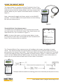
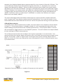
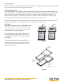
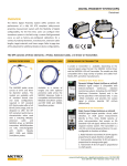
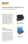
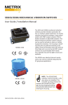
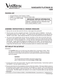
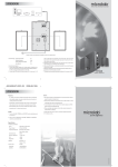
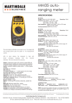
6850-001 Impact Meter
Installation Manual
OVERVIEW
The 6850 Impact Meter is designed for quick
check out or adjustment of Metrix Impact
transmitters, either on an operating machine, or with the transmitter removed.
Simply connect the Meter to an Impact
transmitter, toggle the Power switch, and
select Pulse-Time, 4-20mA, or Peak Detect
mode. In Pulse-Time mode, the transmitter’s Threshold level (milli-volts), and Sample Time (seconds) are displayed, and may
be adjusted while observing the changes.
Switching to 4-20mA mode displays the
current output directly, while Peak Detect
mode displays the peak vibration level, in
milli-volts, detected by the transmitter.
6850 connected
to an IT6810
DOC# 100850 • REV A (JULY 2014)
The Peak Detect mode is provided for
measuring and displaying the amplitude of
Impact peaks present at the measurement
location. Peak Detect mode is most useful
when “fine tuning” a transmitter for a particular machine. An Impact Threshold Level
2X to 3X the base line PD level has proven to
provide good machinery protection monitoring. While the Pulse Time is a function
of machine operating speed, calculated as
follows: 960 divided by machine RPM = the
Pulse Time (in seconds).
FEATURES
•
•
•
•
•
•
•
•
Display peak amplitude of Impacts within machine
Display transmitter’s Impact “Threshold level”
Display transmitter’s Impact “Pulse Time”
Display transmitter’s 4-20mA output
Waveform access through BNC connector
Powers 6810 or 6812 during setup & checkout
Select transmitter’s Pulse-Time, 4-20mA, or Peak Detect mode
Battery powered, digital display
BENEFITS
• One device for transmitter checkout & setup
• Eliminates need for oscilloscope & voltmeters
• Simple to operate for task efficiency
6850 OPERATION / OPERATING MODES
The 6850 Impact Meter is designed for quick check out or adjustment of Metrix Impact
transmitters, either on an operating machine, or with the transmitter removed.
Simply connect the Meter to an Impact transmitter, toggle the Power switch, and select PulseTime, 4-20mA, or Peak Detect mode. In Pulse-Time mode, the transmitter’s Threshold level
(millivolts), and Sample Time (seconds) are displayed, and may be adjusted while observing
the changes. Switching to 4-20mA mode displays the current output directly, while Peak Detect mode displays the peak vibration level, in milli-volts, detected by the transmitter.
The Peak Detect mode is provided for measuring and displaying the amplitude of Impact
peaks present at the measurement location. Peak Detect mode is most useful when “fine
tuning” a transmitter for a particular machine. An Impact Threshold Level 2X to 3X the base
line PD level has proven to provide good machinery protection monitoring. While the Pulse
Time is a function of machine operating speed, calculated as follows: 960 divided by machine RPM = Pulse Time (seconds).
Doc# 100850 • REV A (August 2014) Page 2 of 8
USING THE IMPACT METER
The Impact Meter is capable of taking Threshold, Pulse Time,
Loop Current, and Peak Detect measurements. Prior to taking
measurements with the Impact Meter, you must connect the
Impact Meter to your Impact Transmitter device as shown in
Figure 1.
Next, momentarily toggle the Power switch to the ON/OFF
position. This will initialize the Impact Meter to start making
the desired measurement.
Figure 1
Threshold/Pulse Time Measurement
To initialize the Threshold/Pulse-Time measurement mode,
set input switch 2 to Threshold, Pulse-Time, Peak Detect and
input switch 3 to T/PT as shown in Figure 2.
NOTE: During initial power on of the Impact Meter, it may
be necessary to wait up to 10 seconds for the Threshold and
Pulse-Time measurements to stabilize.
Figure 2
The Threshold/Pulse-Time measurement will configure the impact transmitter in setup
mode. This mode will allow the Impact Meter to measure the Threshold and Pulse-Time
generated by the Impact Transmitter. The Impact Meter will display the measured Threshold
in milli-volts and the Pulse Time in seconds as shown below in Figure 3. Refer to section 5.3
and 5.4 of the IT6810/IT6811/IT6812 Impact Transmitter Manual for more information on
how to set the threshold and pulse-time of the Impact Transmitter.
Example of time waveform showing pulse level and time period (not to scale)
Figure 3
Doc# 100850 • REV A (August 2014) Page 3 of 8
Peak Detect Measurement
To initialize the Peak Detect measurement mode, set input switch 2 to Threshold, PulseTime, Peak Detect and input switch 3 to PD as shown in Figure 2. If the Impact Meter is
already turned on, it will automatically detect the new switch setting and proceed with the
Peak Detect measurement. If the Impact Meter is turned off, momentarily toggle switch 1
to the ON/OFF position. This will initialize the Impact Meter to start making Peak Detect
measurements.
During initialization of the peak detect measurement; the Impact Meter will display “Initializing Peak Detect” as shown in figure 4. The Impact Meter measures the pulse time period
setting of the Impact Transmitter and uses this to determine the internal timing of the
measurement.
NOTE: Since the peak detect measurement is reliant on
a stable pulse time setting of the Impact Transmitter, it
is important not to adjust the pulse time on the Impact
Transmitter while taking a peak detect measurement.
The Peak Detect mode enables the Impact Meter to measure the Peak
impact voltage levels generated by the Impact Transmitter. Refer to
Figure 5 for an example of a typical measurement.
The peak detect measurement displays the peak voltage, Figure 6,
amplitude (Impact Level) that is present during one pulse time period.
The displayed value will increase if the last value measured is higher
than the previous value measured. The displayed value will decrease
if the new peak value is less than ½ of the previous peak value. For
Figure 4
Figure 5
Doc# 100850 • REV A (August 2014) Page 4 of 8
example, the displayed peak detect measurement for t1 as shown in Figure 8 is 320mV. This
is the maximum impact level detected during the pulse time t1. During t2, the maximum
impact level detected is 400mV. Since this value is greater than 320mV, the impact meter
will display the new value of 400mV. During t3, the maximum impact level detected is again
320mV. However, the impact meter will continue to display 400mV since the previous value
is slightly larger but not smaller by half. During t4, the maximum impact level detected is
180mV. Since this value is smaller than ½ of 400mV or smaller than 200mV, the Impact
Meter will now display 180mV.
The main advantage of the peak detect measurement is that it provides a stable maximum
peak “impact level” that may be used to set the Threshold level. As a rule of thumb, it is recommended that the threshold level be set 2 to 3 times the peak level during normal operation.
4-20mA Measurement
To initialize the 4-20mA measurement mode, set input switch 2 to 4-20mA as shown below
in Figure 2. If the Impact Meter is already turned on, it will automatically detect the new
switch setting and proceed with the 4-20mA measurement. If the Impact Meter is turned
off, momentarily toggle switch 1 to the ON/OFF position. This will initialize the Impact Meter
to start making a 4-20mA measurement.
The 4-20mA measurement will configure the impact transmitter in normal mode. This
mode will allow the Impact Meter to measure the 4 to 20mA loop current generated by the
Impact Transmitter. Refer to Figure 8 for an example of a typical 4-20mA measurement.
Refer to section 6 of this user manual for more information on the 4 to 20mA impact severity measurement.
Example of current output vs. number of impacts per time period.
Impacts
0
1
2
3
4
5
6
7
8
9
10
11
12
13
14
15
16
mA
4
5
6
7
8
9
10
11
12
13
14
15
16
17
18
19
20
Figure 6
Doc# 100850 • REV A (August 2014) Page 5 of 8
Dynamic Signal
A BNC Connector is provided on the Impact Meter for viewing the impact waveform through
the use of a scope or other measurement device.
Battery Replacement
The Impact Meter is designed to offer approximately 8 hours of continuous operation under
normal conditions. The Impact Meter checks for low batteries during power up. During this
time, the Impact Meter will display “Low Battery Voltage Detected, Replace Batteries” as
shown below in Figure 7 if the battery power is too low. After receiving this message, the
batteries should be replaced to avoid any potential measurement errors.
To replace the batteries on the Impact Meter, remove the 6 screws on the back of the case
as shown in Figure 8. This will allow access to the battery compartment.
Shut Down
To preserve battery life, the Impact Meter will
shut down power on its own. This time may
vary between 5- and 15-minutes depending
on which mode it is operating in.
Alternatively, the power to the device may
be turned off by holding down switch 1 in
the ON/OFF position for 5 seconds and then
releasing it.
The Impact Meter will also automatically
detect when an Impact Transmitter is not
connected and will shut down on its own to
preserve battery life.
Figure 7
Figure 8
Doc# 100850 • REV A (August 2014) Page 6 of 8
Doc# 100850 • REV A (August 2014) Page 7 of 8
ENVIRONMENTAL INFORMATION
This electronic equipment was manufactured according to high quality standards to ensure safe and reliable operation when used as intended. Due to its
nature, this equipment may contain small quantities of substances known to be
hazardous to the environment or to human health if released into the environment. For this reason, Waste Electrical and Electronic Equipment (commonly
known as WEEE) should never be disposed of in the public waste stream. The
“Crossed-Out Waste Bin” label affixed to this product is a reminder to dispose
of this product in accordance with local WEEE regulations. If you have questions about the disposal process, please contact Metrix Customer Services.
[email protected]
www.metrixvibration.com
8824 Fallbrook Dr. Houston, TX 77064, USA
Tel: 1.281.940.1802 • Fax: 1.713.559.9421
After Hours (CST) Technical Assistance: 1.713.452.9703
Doc# 100850 • REV A (August 2014) Page 8 of 8