1
IP Office Basic Edition
IP Office Basic Edition - Quick Mode
8.1 FP1 Manager
- Issue 05g 0 (Monday, October 15, 2012)
© 2012 AVAYA All Rights Reserved.
Notices
While reasonable efforts have been made to ensure that the information in
this document is complete and accurate at the time of printing, Avaya assumes
no liability for any errors. Avaya reserves the right to make changes and
corrections to the information in this document without the obligation to notify
any person or organization of such changes.
Documentation disclaimer
Avaya shall not be responsible for any modifications, additions, or deletions to
the original published version of this documentation unless such modifications,
additions, or deletions were performed by Avaya.
End User agree to indemnify and hold harmless Avaya, Avaya's agents,
servants and employees against all claims, lawsuits, demands and judgments
arising out of, or in connection with, subsequent modifications, additions or
deletions to this documentation, to the extent made by End User.
Link disclaimer
Avaya is not responsible for the contents or reliability of any linked Web sites
referenced within this site or documentation(s) provided by Avaya. Avaya is
not responsible for the accuracy of any information, statement or content
provided on these sites and does not necessarily endorse the products,
services, or information described or offered within them. Avaya does not
guarantee that these links will work all the time and has no control over the
availability of the linked pages.
Warranty
Avaya provides a limited warranty on this product. Refer to your sales
agreement to establish the terms of the limited warranty. In addition, Avaya’s
standard warranty language, as well as information regarding support for this
product, while under warranty, is available to Avaya customers and other
parties through the Avaya Support Web site: http://www.avaya.com/support.
Please note that if you acquired the product from an authorized Avaya reseller
outside of the United States and Canada, the warranty is provided to you by
said Avaya reseller and not by Avaya.
Licenses
THE SOFTWARE LICENSE TERMS AVAILABLE ON THE AVAYA WEBSITE,
HTTP://SUPPORT.AVAYA.COM/LICENSEINFO/ ARE APPLICABLE TO ANYONE
WHO DOWNLOADS, USES AND/OR INSTALLS AVAYA SOFTWARE, PURCHASED
FROM AVAYA INC., ANY AVAYA AFFILIATE, OR AN AUTHORIZED AVAYA
RESELLER (AS APPLICABLE) UNDER A COMMERCIAL AGREEMENT WITH
AVAYA OR AN AUTHORIZED AVAYA RESELLER. UNLESS OTHERWISE AGREED
TO BY AVAYA IN WRITING, AVAYA DOES NOT EXTEND THIS LICENSE IF THE
SOFTWARE WAS OBTAINED FROM ANYONE OTHER THAN AVAYA, AN AVAYA
AFFILIATE OR AN AVAYA AUTHORIZED RESELLER, AND AVAYA RESERVES
THE RIGHT TO TAKE LEGAL ACTION AGAINST YOU AND ANYONE ELSE USING
OR SELLING THE SOFTWARE WITHOUT A LICENSE. BY INSTALLING,
DOWNLOADING OR USING THE SOFTWARE, OR AUTHORIZING OTHERS TO
DO SO, YOU, ON BEHALF OF YOURSELF AND THE ENTITY FOR WHOM YOU
ARE INSTALLING, DOWNLOADING OR USING THE SOFTWARE (HEREINAFTER
REFERRED TO INTERCHANGEABLY AS “YOU” AND “END USER”), AGREE TO
THESE TERMS AND CONDITIONS AND CREATE A BINDING CONTRACT
BETWEEN YOU AND AVAYA INC. OR THE APPLICABLE AVAYA AFFILIATE
(“AVAYA”).
Avaya grants End User a license within the scope of the license types described
below. The applicable number of licenses and units of capacity for which the
license is granted will be one (1), unless a different number of licenses or units
of capacity is specified in the Documentation or other materials available to
End User. "Designated Processor" means a single stand-alone computing
device. "Server" means a Designated Processor that hosts a software
application to be accessed by multiple users. "Software" means the computer
programs in object code, originally licensed by Avaya and ultimately utilized by
End User, whether as stand-alone products or pre-installed on Hardware.
"Hardware" means the standard hardware originally sold by Avaya and
ultimately utilized by End User.
IP Office Basic Edition - Quick Mode 8.1 FP1 Manager
IP Office Basic Edition
License types
Designated System(s) License (DS). End User may install and use each copy of
the Software on only one Designated Processor, unless a different number of
Designated Processors is indicated in the Documentation or other materials
available to End User. Avaya may require the Designated Processor(s) to be
identified by type, serial number, feature key, location or other specific
designation, or to be provided by End User to Avaya through electronic means
established by Avaya specifically for this purpose.
Copyright
Except where expressly stated otherwise, no use should be made of materials
on this site, the Documentation(s) and Product(s) provided by Avaya. All
content on this site, the documentation(s) and the product(s) provided by
Avaya including the selection, arrangement and design of the content is owned
either by Avaya or its licensors and is protected by copyright and other
intellectual property laws including the sui generis rights relating to the
protection of databases. You may not modify, copy, reproduce, republish,
upload, post, transmit or distribute in any way any content, in whole or in part,
including any code and software. Unauthorized reproduction, transmission,
dissemination, storage, and or use without the express written consent of
Avaya can be a criminal, as well as a civil, offense under the applicable law.
Third Party Components
Certain software programs or portions thereof included in the Product may
contain software distributed under third party agreements ("Third Party
Components"), which may contain terms that expand or limit rights to use
certain portions of the Product ("Third Party Terms"). Information regarding
distributed Linux OS source code (for those Products that have distributed the
Linux OS source code), and identifying the copyright holders of the Third Party
Components and the Third Party Terms that apply to them is available on the
Avaya Support Web site: http://support.avaya.com/Copyright.
Preventing toll fraud
"Toll fraud" is the unauthorized use of your telecommunications system by an
unauthorized party (for example, a person who is not a corporate employee,
agent, subcontractor, or is not working on your company's behalf). Be aware
that there can be a risk of toll fraud associated with your system and that, if
toll fraud occurs, it can result in substantial additional charges for your
telecommunications services.
Avaya fraud intervention
If you suspect that you are being victimized by toll fraud and you need
technical assistance or support, call Technical Service Center Toll Fraud
Intervention Hotline at +1-800-643-2353 for the United States and Canada.
For additional support telephone numbers, see the Avaya Support Web site:
http://support.avaya.com
Suspected security vulnerabilities with Avaya products should be reported to
Avaya by sending mail to: [email protected].
Trademarks
Avaya and Aura are trademarks of Avaya, Inc.
The trademarks, logos and service marks (“Marks”) displayed in this site, the
documentation(s) and product(s) provided by Avaya are the registered or
unregistered Marks of Avaya, its affiliates, or other third parties. Users are not
permitted to use such Marks without prior written consent from Avaya or such
third party which may own the Mark. Nothing contained in this site, the
documentation(s) and product(s) should be construed as granting, by
implication, estoppel, or otherwise, any license or right in and to the Marks
without the express written permission of Avaya or the applicable third party.
Avaya is a registered trademark of Avaya Inc. All non-Avaya trademarks are
the property of their respective owners.
Downloading documents
For the most current versions of documentation, see the Avaya Support Web
site: http://www.avaya.com/support
Contact Avaya Support
Avaya provides a telephone number for you to use to report problems or to
ask questions about your product. The support telephone number is
1-800-242-2121 in the United States. For additional support telephone
numbers, see the Avaya Web site: http://www.avaya.com/support
Page 2
- Issue 05g (Monday, October 15, 2012)
Contents
Contents
1. Telephony Features
1.1 What's New.....................................................................
in Release 8.0
9
1.2 Key System
.....................................................................
or PBX System
11
1.2.1 Outgoing
............................................................................
Call Routing
11
1.2.2 Incoming
............................................................................
Call Routing
13
1.3 Dial Plan ..................................................................... 17
1.4 Date and Time
.....................................................................
Setting
20
1.5 Voicemail Operation
..................................................................... 20
1.6 Night Service
..................................................................... 21
1.7 Phantom Extensions
..................................................................... 22
1.8 One Touch.....................................................................
Transfer
23
1.9 Modem Access
.....................................................................
Support
23
1.10 SIP Trunks
..................................................................... 23
2. The Manager Application
2.1 Installing Manager
.....................................................................
2.2 Starting Manager
.....................................................................
2.3 Setting the.....................................................................
Discovery Addresses
2.4 Known IP Office
.....................................................................
Discovery
2.5 Saving the .....................................................................
Configuration
2.6 Saving a Configuration
.....................................................................
to a PC File
2.7 Loading a PC
.....................................................................
File
2.8 Simplified View
.....................................................................
2.9 Advanced View
.....................................................................
2.10 The System
.....................................................................
Page
2.11 The Admin
.....................................................................
Tasks List
2.12 Creating a.....................................................................
Configuration File
29
31
33
35
37
39
39
40
41
42
43
44
3. Configuration Settings
3.1 Remote/Administrator
.....................................................................
Password
47
3.2 System Settings
..................................................................... 48
3.2.1 List
............................................................................
Management
52
3.2.2 Speed
............................................................................
Dial Setup
57
3.2.3 License
............................................................................
Management
59
3.3 User Setup..................................................................... 61
3.3.1 Button
............................................................................
Programming
63
3.3.2 Advanced
............................................................................
Settings
72
3.3.3 DND
............................................................................
Exception List
76
3.4 Group Management
..................................................................... 77
3.5 Trunks
..................................................................... 80
3.5.1 Analog
............................................................................
Trunks
81
3.5.2 BRI
............................................................................
Trunk
87
3.5.3 PRI
............................................................................
Trunks
91
3.5.4............................................................................
SIP Trunk Administration
111
3.5.5............................................................................
Outbound Call Handling
122
3.6 Auxiliary Equipment
..................................................................... 127
3.6.1............................................................................
Door Phone
128
3.6.2............................................................................
Music on Hold
129
3.6.3............................................................................
SMDR
130
3.6.4............................................................................
Contact Closure Group
131
3.7 Auto Attendant
.....................................................................
Setup
132
3.8 Advanced.....................................................................
Parameters
138
4. Button Programming
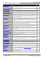
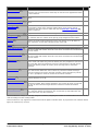
4.1 Button Programming
.....................................................................
Functions
145
IP Office Basic Edition - Quick Mode 8.1 FP1 Manager
IP Office Basic Edition
4.2 Manager .....................................................................
Buttons
4.3 Absent Message
.....................................................................
4.4 Account Code
.....................................................................
Entry
4.5 Active Line
.....................................................................
Pickup
4.6 Auto Dial .....................................................................
- Intercom
4.7 Auto Dial .....................................................................
- Other
4.8 Call Coverage
.....................................................................
4.9 Call Forwarding
.....................................................................
4.10 Call Pickup
.....................................................................
4.11 Caller ID.....................................................................
Inspect
4.12 Caller ID.....................................................................
Log
4.13 Caller ID.....................................................................
Name Display
4.14 Calling Group
.....................................................................
4.15 Call Screening
.....................................................................
4.16 Conference
.....................................................................
Drop
4.17 Contact .....................................................................
Closure 1
4.18 Contact .....................................................................
Closure 2
4.19 Do Not Disturb
.....................................................................
4.20 Hot Dial .....................................................................
4.21 Hunt Group
.....................................................................
4.22 Idle Line.....................................................................
Pickup
4.23 Last Number
.....................................................................
Redial
4.24 Loudspeaker
.....................................................................
Page
4.25 Message.....................................................................
Alert Notification
4.26 Night Service
.....................................................................
4.27 Pickup Group
.....................................................................
4.28 Privacy .....................................................................
4.29 Recall .....................................................................
4.30 Saved Number
.....................................................................
Redial
4.31 Simultaneous
.....................................................................
Page
4.32 Station Lock
.....................................................................
4.33 Station Unlock
.....................................................................
4.34 VMS Cover
.....................................................................
4.35 Voice Mailbox
.....................................................................
Transfer
4.36 Wake Up.....................................................................
Service
147
148
148
148
148
148
149
149
150
150
150
150
150
151
153
153
153
153
154
154
154
154
154
154
155
155
155
155
156
156
156
156
156
157
158
5. Manager Menu Commands
5.1 File Menu.....................................................................
5.1.1............................................................................
Open Configuration
5.1.2............................................................................
Close Configuration
5.1.3............................................................................
Save Configuration
5.1.4............................................................................
Save Configuration As
5.1.5............................................................................
Preferences
5.1.6............................................................................
Offline
5.1.7............................................................................
Advanced
5.1.8............................................................................
Exit
5.2 View
.....................................................................
5.2.1............................................................................
Toolbars
5.2.2............................................................................
Tool Tip
5.2.3............................................................................
Advanced View
5.2.4............................................................................
Hide Admin Tasks
5.2.5............................................................................
TFTP Log
5.3 Tools
.....................................................................
5.3.1............................................................................
Extension Renumber
5.3.2............................................................................
Import Templates
5.4 Embedded
.....................................................................
File Management
5.4.1............................................................................
Open File Settings
161
161
161
161
161
161
169
170
180
181
181
181
181
181
181
182
182
182
183
184
Page 3
- Issue 05g (Monday, October 15, 2012)
5.4.2............................................................................
Close File Settings
5.4.3............................................................................
Refresh File Settings
5.4.4............................................................................
Upload File
5.4.5............................................................................
Upload System Files
5.4.6............................................................................
Backup System Files
5.4.7............................................................................
Restore System Files
5.4.8............................................................................
Upgrade Binaries
5.4.9............................................................................
Upgrade Configuration
5.4.10
............................................................................
Upload Voicemail Files
5.4.11
............................................................................
Copy System Card
5.4.12
............................................................................
Configuration
184
184
184
184
184
184
184
184
185
185
185
6. Appendix: SMDR
6.1 SMDR Fields
..................................................................... 188
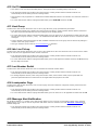
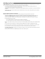
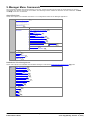
6.2 SMDR Examples
..................................................................... 191
7. Other System Administration Tools
7.1 Phone Based
.....................................................................
Administration
208
Index ...............................................................................211
IP Office Basic Edition - Quick Mode 8.1 FP1 Manager
IP Office Basic Edition
Page 4
- Issue 05g (Monday, October 15, 2012)
Chapter 1.
Telephony Features
IP Office Basic Edition - Quick Mode 8.1 FP1 Manager
IP Office Basic Edition
Page 5
- Issue 05g (Monday, October 15, 2012)
1. Telephony Features
This section covers details of the feature configurable for an IP Office Basic Edition - Quick Mode system using IP Office
Manager. It is an operating mode of IP Office that support up to 32 analogue trunks and 100 users (100 if using a 3 digit
dial plan, 48 is using a 2 digit dial plan).
It is the default mode assumed by a IP500v2 control unit fitted with a new IP Office A-Law or IP Office U-Law SD card. In
addition to analogue trunks, SIP trunks and digital (BRI or PRI) trunks are also supported.
IP Office Basic Edition - Quick Mode itself also operates in either of two system modes; behaving as either a key system
or a PBX system 11 . Systems with an Mu-Law SD card default to Key system operation, those with an A-Law SD card
default to PBX system operation. However this setting can be changed within the system configuration if required.
IP Office Basic Edition - Quick Mode mode systems can be changed to IP Office standard mode operation if required. This
is done by selecting using IP Office Manager (File | Advanced | Switch to Standard Mode 175 ).
Supported Phones
The following phones are supported by IP Office Basic Edition - Quick Mode systems running IP Office Release 8.1 FP1
software.
· Avaya DS Digital Stations
These phones use digital station (DS) ports provided by IP500 base cards (DS8 and Combo DS6-P2). They can
also use the DS ports provided by Digital Station 16 and Digital Station 30 external expansion modules.
· Avaya 1400 Series: 1403, 1408 and 1416.
· Avaya 9500 Series: 9504 and 9508.
· Avaya TCM Digital Stations
These phone use ports provided by the IP500 TCM8 base card or by DS16A/DS30A external expansion modules.
· Avaya M-Series: MT7100, MT7100N, MT7208, MT7208N, M7310, M7310N, M7324 and M7324N.
· Avaya T-Series: T7000, T7100, T7208, T7316, T7316E.
· Other Phones: Avaya 4100 Series, Avaya 7400 Series and Audio Conferencing Unit (ACU).
· Additional programmable buttons are supported by the addition of button modules on M7324 and T7316E
phones.
· Avaya ETR Phones
Avaya ETR (Enhanced Tip and Ring) phones are supported on both Avaya PARTNER ACS telephone systems and IP
Office Basic Edition - Quick Mode systems. On IP Office systems they connect to ETR ports provided by IP500
ETR6 base cards.
· ACS "Refreshed" Series: ETR6D, ETR18D, ETR34D.
· ACS "Euro" Series: ETR6, ETR18, ETR18D, ETR34D.
· Avaya DECT Phones: 3920.
This DECT phone consists of a paired base station and cordless handset. It connects to ports provided by the
IP500 ETR6 base card. Supported in North America only.
· Analog Phones
The IP Office Basic Edition - Quick Mode system supports DTMF analog phones. These connect to PHONE extension
ports provided by IP500 base cards (Phone 2, Phone 8 and Combo DS6-P2) or external expansion modules (
Phone 16 and Phone 30). Avaya cannot guarantee the operation of any specific non-Avaya analog phones on an
IP Office Basic Edition - Quick Mode system. Analog phones can also be connected to ports on the IP500 ETR6
base card.
IP500 Base Cards
The IP Office control unit can be fitted with up to 4 IP500 base cards. Each base card can be fitted with an IP500 trunk
daughter card. The following IP500 base cards are supported by IP Office Basic Edition - Quick Mode:
· Digital Station Base Card: DS8
This type of base card provides 8 DS ports for the connection of Avaya digital stations. Maximum 3 cards
supported.
· Analogue Extension Base Cards: Phone 2, Phone 8.
This type of base card provides 2 or 8 ports respectively for the connection of DTMF analog extension phones.
Maximum 4 cards supported.
· Combination Base Card: Combo DS6-P2-VCM10-ATM4 and Combo DS6-P2-VCM10-BRI4.
This type of base card provides 6 DS ports for the connection of Avaya digital stations and 2 PHONE ports for the
connection of DTMF analog extension phones. It also provides 10 voice compression channels (VCM) needed for
SIP trunk operation. The card is available in 2 variants, one pre-fitted with an ATM4 trunk daughter card, the other
pre-fitted with a BRI4 trunk daughter card. Maximum 2 cards supported.
IP Office Basic Edition - Quick Mode 8.1 FP1 Manager
IP Office Basic Edition
Page 6
- Issue 05g (Monday, October 15, 2012)
Telephony Features:
· TCM Base Card: TCM 8
This type of base card provides 8 TCM ports for the connection of Avaya Nortel digital stations. Maximum 4 cards
supported.
IP500 Trunk Daughter Cards
Each IP500 base card supported by IP Office Basic Edition - Quick Mode can be fitted with an IP500 trunk daughter card
(on IP500 Combination cards the trunk daughter card is pre-fitted and cannot be changed). The following IP500 trunk
daughter cards are supported by IP Office Basic Edition - Quick Mode. Note that PRI and BRI trunks are not supported in
the same system.
· Analogue Trunk Card: ATM 4 UNI
This type of trunk daughter card allows the base card to which it is fitted to support up to 4 analog trunk
connections.
· ISDN BRI Trunk Cards: BRI 4 UNI and BRI 8 UNI
These type of trunk daughter cards allow the base card to which they are fitted to support ISDN BRI trunks. The
card is available in 2 trunk (4 channel) and 4 trunk (8 channel) variants. This type of card is not supported in
North American locales. The IP Office Basic Edition - Quick Mode system is limited to one ISDN trunk card per
system. A combination of cards is supported so long as no more than 12 channels are installed
· ISDN PRI Trunk Card: PRI 1 UNI
This type of trunk daughter card allows the base card to which it is fitted to support PRI trunks. The type of PRI
trunk (E1 PRI, US PRI or T1) is determined by the system locale. Note that the channels supported by the card
require licenses entered into the system configuration. The card supports only 8 unlicensed channels.
External Expansion Modules
The system can be expanded by the addition of up to 8 external expansion modules, so long as the system extension and
trunk support limits are not exceeded.
· Analog Trunk Module: ATM 16
This type of external expansion module supports 16 analog trunks.
· Digital Station Modules: DS16, DS16 V2, DS30, DS30 V2
These types of external expansion modules support 16 or 30 DS ports for Avaya digital station phones.
· Advanced Digital Station Modules: DS16A, DS30A
These types of external expansion modules support 16 or 30 ports which can be used as TCM ports for the
connection of Avaya Nortel digital stations.
· Analog Phone Modules: Phone 8, Phone 16, Phone 30
These types of external expansion modules support 16 or 30 PHONE ports respectively for the connection of DTMF
analog extensions.
Licenses
Licenses are required for some features of IP Office Basic Edition - Quick Mode operation. The license keys are entered
into the system configuration and are based on the unique Feature Key number of the SD card installed in the system
and the feature being enabled.
· Software Upgrade Licenses
Existing systems being upgraded to IP Office Release 7.0 will require an upgrade license.
· New IP500v2 Systems
For the first 90 days, a new IP500v2 control unit will run any supported IP Office Release without
requiring an upgrade license. The highest level run is written into the system's memory (not the
SD card) and that becomes a permanent entitlement for the control unit. However, after 90 days
the IP500v2 will require an upgrade license if upgraded to a software release higher than any
that it has run in the initial 90 day period.
·
Warning
Systems upgraded without the appropriate license will display "No license available" and will not
allow any telephony functions.
· SIP Trunk Channel Licenses
The system can support 3 simultaneous SIP calls without needing licenses. Additional simultaneous calls, up to
20 in total, require the addition of licenses 59 to the configuration.
· VCM Channels
Note that for SIP calls the system also requires VCM channels. For a IP Office Basic Edition - Quick Mode
system those are provided by installing IP500 Combination base cards. Each of these cards provides 10
VCM channels.
IP Office Basic Edition - Quick Mode 8.1 FP1 Manager
IP Office Basic Edition
Page 7
- Issue 05g (Monday, October 15, 2012)
· IP500 PRI Channel Licenses
The IP500 PRI 1 trunk daughter card supports the use of its first 8 channels unlicensed. Use of additional
channels require licenses to be added to the configuration. The maximum number of channels depends on the
current Line Sub-Type setting of the PRI trunk.
· Embedded Voicemail Additional Ports
Unlicensed, the Embedded Voicemail provided by the system supports 2 simultaneous connections and 15
hours of storage. This can be expanded up to 6 channels by the addition of licenses, each of which enables an
additional two channels. For IP Office Release7.0+ each license also enables an additional 5 hours of storage.
IP Office Basic Edition - Quick Mode 8.1 FP1 Manager
IP Office Basic Edition
Page 8
- Issue 05g (Monday, October 15, 2012)
Telephony Features:
1.1 What's New in Release 8.0
The following changes and additional features have been made for an IP Office Basic Edition - Quick Mode system running
IP Office Release 8.0 software.
· Name Changes
The name for these systems has changed from IP Office Essential Edition - Norstar Mode, IP Office Essential
Edition - PARTNER Mode and IP Office Essential Edition - Quick Mode to IP Office Basic Edition - Norstar Mode, IP
Office Basic Edition - PARTNER Mode and IP Office Basic Edition. This is to clarify the operational and functional
distinction from IP Office Essential Edition, IP Office Preferred Edition and IP Office Advanced Edition modes.
· Changed Default Administrator Password
The default password for the Administrator account used for access to the system using IP Office Manager has
changed from password to Administrator. This applies to new systems and to systems that are defaulted.
· Phone Based Administration During a Call
The ability to enter and use phone base administration menus during a call is now supported on all phone types
capable of phone based administration. Previously this option was limited to ETR, M-Series and T-Series phones. It
includes entering system, centralized and personal telephone administration.
· IP Office Web Manager
Systems can now be configured via web browser. The default access is via the same Administrator account as
used for IP Office Manager and via a new default BusinessPartner account. The BusinessPartner account can
be used to create additional user accounts for IP Office Web Manager and to set what aspects of the configuration
those additional accounts can change.
· Analog Trunk Unsupervised Disconnect Operation
In areas where no disconnect clear signalling or reliable tone disconnect is available, the system operation can be
set for unsupervised disconnect on analog trunks. When enabled, unsupervised transfers and trunk to trunk
transfers to analog trunks are not allowed.
· Intuity Mode Embedded Voicemail Support
Previous software releases have used IP Office mode key presses to navigate the Embedded Voicemail menus. The
system now supports Intuity mode key presses. The mode used by the system is selectable. Intuity mode is the
default used for new systems.
· Prompt Set Upgrade Changes
Previously for IP500 V2 systems, when upgrading the system files all files were updated including the sets of
prompt files for all languages supported by Embedded Voicemail. For IP Office Release 8.0, the following changes
have been made:
· When upgrading the system files, the current configuration of the system is used to determine which files to
include in the upgrade in addition to the system and phone firmware files. This applies when using the Upload
System Files option during a system upgrade (File | Advanced | Upgrade 172 ) or when using Upload
System Files within embedded file management (File | Advanced | Embedded File Management 176 ),
· Embedded voicemail prompts are only upgraded if the system is currently configured to use Embedded
Voicemail. English language prompts are upgraded as follows: IP Office A-Law/Norstar SD Cards - UK
English, IP Office U-Law/PARTNER SD Cards - US English. Other languages are upgraded if they
match the locale languages of the system locale, user locales, incoming call route locales or short code
locales in the system's configuration.
· The files for IP Office Web Manager are only upgraded for systems configured to IP Office Basic Edition Quick Mode, IP Office Basic Edition - PARTNER® Mode or IP Office Basic Edition - Norstar Mode mode.
· When editing the configuration of a system that uses Embedded Voicemail, when the locale of the system, a
user, a short code or an incoming call route is change, IP Office Manager will display a warning if the matching
set of prompts on the System SD card have not be upgraded.
· A new option within IP Office Manager, Add/Display VM locales 179 can be used to display the upgraded
languages on the SD card and to upload an additional language or languages.
· The Recreate IP Office SD Card 177 command still adds all the available Embedded Voicemail language
prompts for all languages and all files for IP Office Web Manager.
· Mobile Twinning No Longer Supported
The mobile twinning features available in previous releases are no longer supported. On existing systems
upgraded to Release 8.0, the related settings such a Mobile Twin buttons are converted to Remote Call
Forward during the upgrade. Any licenses added for mobile twinning are retained but not used. Customers
wanting to use mobile twinning will need to upgrade to IP Office Essential Edition.
· Call Screening
This function is used to enable or disable call screening. While enabled, when a caller is presented to the user's
voicemail mailbox, if the user's phone is idle they will hear through the phone's handsfree speaker the caller
leaving the message and can select to answer or ignore the call.
· SIP Trunk Enhancements
A number of features have been added for SIP trunk operation.
IP Office Basic Edition - Quick Mode 8.1 FP1 Manager
IP Office Basic Edition
Page 9
- Issue 05g (Monday, October 15, 2012)
· Trunk Service Status Checking
The system can regularly check the availability of a SIP trunk in order to ensure that outgoing calls are not
delayed by attempting to use a trunk which is no longer in service.
· Call Routing Method Control
Which part of the incoming call information should be used as the incoming number can now be selected. The
options are to match either the Request URI or the To Header.
· Associate Method Control
The method by which the system associates a incoming SIP call with a particular SIP trunk can be configured.
· Fax Transport Support
Support for fax calls can be enabled if also supported by the line provider. G711 and/or T38 fax support can
be selected.
· PRACK/100 rel Support
This feature is sometimes called 'early media support' and allows features such as in-band call tones and call
progress announcements to be played while the call connection process is still in progress.
IP Office Basic Edition - Quick Mode 8.1 FP1 Manager
IP Office Basic Edition
Page 10
- Issue 05g (Monday, October 15, 2012)
Telephony Features: What's New in Release 8.0
1.2 Key System or PBX System
For IP Office Release 7.0+ the operating mode of a system can be changed. Two modes are supported; key mode and
PBX mode. The selected mode affects a number of controls, mainly around the making of outgoing calls and the routing
of incoming calls.
1.2.1 Outgoing Call Routing
Key Mode
Each phone is configured with 2 Intercom buttons which cannot be changed. It is also configured with line appearance
buttons for specific lines using the Number of Lines settings and individual button programming.
· Internal calls are made by selecting one of the two Intercom buttons provided on each phone and then dialing the
number of another extension or of the system feature required.
· External calls are made by selecting one of the line appearance buttons programmed on the phone and then
dialing the external number required.
· If the user dials without first selecting an Intercom or Line button, the user's automatic line selection setting is
used to determine which button, if available, gets used.
· If an external number is added to contacts, when dialing, it rings on the first available line from the ALS. If there is
no line added to the ALS, the call is not made. If it is an internal number it dials on the intercom.
PBX Mode
Each phone is configured with 3 call appearance buttons (2 only on ETR phones). These can be used to make both
internal and external calls. The dialing of an external call can be indicated by the dialing starting with a specific prefix (9
or 0) if required, otherwise any number not matching an internal extension or function is assumed to be external.
The line used for an outgoing external call is determined by configuration settings. ARS Selectors are created which can
be groups of lines or specific functions using any available ISDN lines. Different external number prefixes are then
mapped to those ARS Selectors. When a user dials an external number, it is matched to a selector and uses the function
and one of the lines specified by that selector. For SIP trunks set to call by call mode, each call by call entry also has an
ARS selector settings which allows it to also be used for outgoing calls.
Line appearances can still be used to make and answer calls on a particular line but are not added by default.
All calls go through intercom. This is true for internal and external calls (ARS). If you enable a prefix for external
numbers, then you must be manually modify the number stored in contacts. If the number was not added before the
prefix option in the Manager was selected, you have to add the number with the selected prefix.
Dialing Restrictions
In both modes, the system uses a number of methods to control the external numbers which users are allowed to call.
· Allowed Number Lists / Disallowed Number Lists
These lists are used in define numbers that can or cannot be dialed. Users are then associated with the different
lists.
Allowed Numbers
Each allowed list contains external telephone numbers that members of the list are allowed to
dial regardless of any other call barring. The users allowed lists override any disallowed lists
54 of which they are also member and the user's Outgoing Call Bar 61 and Outgoing Call
Restrictions 72 settings.
There are eight lists, each containing up to 10 numbers. Each number can use the telephone
dialing digits 0 to 9, *, # and can be up to 28 digits long. You can also use the ? character as a
single digit wildcard.
Disallowed Numbers
Each disallowed list contains external telephone numbers that users who are members of the
list are not allowed to dial.
Numbers in the disallowed lists of which a user is a member are overridden if they also appear
in the allowed numbers lists, emergency number list of which the user is a member and also
by marked system speed dials 57 .
There are eight lists, each containing up to 10 numbers. Each number can use the telephone
dialing digits 0 to 9, *, # and can be up to 28 digits long. You can also use the ? character as a
single digit wildcard.
Emergency Numbers
You can enter 10 emergency phone numbers into this list. This list is applied to all users and
overrides any dialing restrictions that may also be applied to the users.
IP Office Basic Edition - Quick Mode 8.1 FP1 Manager
IP Office Basic Edition
Page 11
- Issue 05g (Monday, October 15, 2012)
· Account Codes
Each user can be configured to need to enter a valid account code whenever they make an external call.
· Outgoing Call Restrictions
For each user, the type of external calls that the user is able to make can be configured.
· Marked Speed Dials
When a user uses a stored system speed dial number, the actual number dialed is subject to all the call barring
methods as if the user had dialed the number directly. However system speed dials set as 'marked speed dials'
override any call restrictions.
· Night Service 21
When the system is set to night service, any users in the Night Service Group need to enter the system
password when making an external call.
IP Office Basic Edition - Quick Mode 8.1 FP1 Manager
IP Office Basic Edition
Page 12
- Issue 05g (Monday, October 15, 2012)
Telephony Features: Key System or PBX System
1.2.2 Incoming Call Routing
The options for routing incoming calls depend on whether the system is set to PBX or Key mode.
Key Mode
For an incoming external calls on a line, the following options control where the call is presented:
· Line Appearance Buttons
The call will alert on any line appearance buttons that matches the line. Each line has a line number which can be
assigned to line appearance buttons on users' phones. Users can answer the call by pressing the alerting line
appearance button on their phone.
· Number of Lines
By default, all analog lines in the system are assigned to line appearance buttons when the system is installed.
Lines are assigned for all users starting from button 03 upwards in order of line numbering.
· Line Assignment 71
Through individual user button programming, any programmable button can be configured as a line
appearance for a particular line.
· Coverage Destination
The Coverage Destination setting of each line can be used to select whether an incoming call on that line is also
presented to one of the following options in addition to alerting on any matching line appearances. For PRI and BRI
trunks, it is not possible to know on which of the trunk's channels incoming calls will arrive. Therefore in most cases,
the coverage destination and other settings of each line on the trunk should be set to the same values.
· Coverage Extension
The call alerts on an intercom button of a selected line coverage extension. The user's call coverage, VMS
coverage and call forwarding settings are applied to the call. Any extension can be used as the destination
including a phantom extension.
· Hunt Group
The call is presented, in sequence, to each of the available members of a selected hunt group until answered.
Any of the 6 sequential hunt groups can be used as the destination.
· Auto Attendant Coverage
Each line can be configured to send unanswered calls to an auto attendant after a set delay (which can be set to 0
for immediate answer). This can be set to operate when the system is in day and or night service. This is done
using the VMS Schedule, VMS Delay - Day, VMS Delay - Night and VMS Auto Attendant settings of each
line.
The following methods can be used to override the normal call routing detailed above:
· DID Call Mapping
For BRI, ETSI PRI and PRI trunks, if the incoming call matches a configured DID and or ICLID number, the
Coverage Destination setting for the DID/ICLID match is used rather than the line's Coverage Destination.
DID can also be used on some types of T1 trunk.
· SIP Call by Call Table
For SIP trunks, if the incoming call matches a configured URI, it is presented to the extension or group specified in
the SIP line's Call by Call Table.
· Night Service 21
Switching on night service overrides the routing of calls to Coverage Destinations. Instead the calls change to
alerting the users who are members of the Night Service group. The settings for auto attendant coverage (VMS
Schedule) can also be varied depending on whether the system is in night service or not.
IP Office Basic Edition - Quick Mode 8.1 FP1 Manager
IP Office Basic Edition
Page 13
- Issue 05g (Monday, October 15, 2012)
PBX Mode
In PBX mode, a new group, the Operator Group, is used as a the default destination for call. This group contains the
first extension on the system.
· For analog trunks trunks, the trunk's Coverage Destination is defaulted to the Operator Group but can be
changed if required.
· For PRI and BRI trunks all incoming call routing is done by DID Call Mapping. Each DID table has a non-removable
default route which is used for any calls that do not match any other specific DID entry. The destination for this
default entry is the Operator Group.
· SIP trunks are defaulted to call by call operation, again with a default call by call destination of the Operator
Group.
The following new destinations for incoming calls are available:
· Operator Group
This group is the default destination for all incoming calls. The group contains the first extension on the system but
can be edited to contain other extensions.
· Calling Groups
In Key mode these 4 groups are only used internally. In PBX mode these groups are also available as a
destination for trunk calls in the Coverage Destination selections, DID Call Mapping and SIP Call by Call tables.
A calling group can also be selected as the destination for an auto-attendant transfer.
Night Service Mode
In both modes, when the system is put into night service 21 , all incoming calls except those to specific DID call mapping
or SIP call by call destinations, are rerouted to alert the users who are members of the night service group.
IP Office Basic Edition - Quick Mode 8.1 FP1 Manager
IP Office Basic Edition
Page 14
- Issue 05g (Monday, October 15, 2012)
Telephony Features: Key System or PBX System
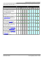
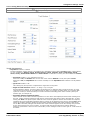
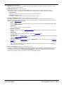
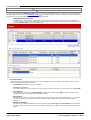
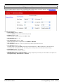
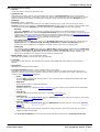
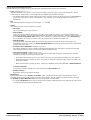
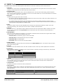
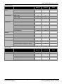
1.2.2.1 Coverage Destination Summary
The table below summarizes the supported destinations for coverage destinations. The options depend on the trunk type
and the operating mode of the system.
Coverage Destinations
Key Mode
Alog BRI ETSI PRI
PRI
· None
If set to None, incoming calls will only
alert on user extensions with line
appearance buttons that match the
line's Appearance ID.
*
*
*
*
PBX Mode
T1
SIP
*
*
Alog BRI ETSI PRI
PRI
–
–
–
· Extension
Route incoming calls to a particular
extension.
–
–
–
· Phantom Extension
IP Office Release 6.1+ supports
phantom extensions 22 . One of these
can be selected as the destination for
calls.
–
–
–
· Hunt Group
Incoming calls can be routed to one of
the 6 sequential hunt groups 77 .
–
–
–
· Voicemail
Route incoming calls to the systems
voicemail to collect messages. This
requires the caller to know the mailbox
number and passcode.
–
–
–
–
–
–
–
–
–
· Operator Group
For systems with their System Mode
48 set to PBX System, incoming calls
are routed to the Operator Group 77 .
–
–
–
–
–
–
· Calling Group
For systems with their System Mode
48 set to PBX System, incoming calls
can be routed to one of the 4 collective
calling groups 77 .
–
–
–
–
–
–
*
T1
SIP
*
*
–
* = Default destination.
IP Office Basic Edition - Quick Mode 8.1 FP1 Manager
IP Office Basic Edition
Page 15
- Issue 05g (Monday, October 15, 2012)
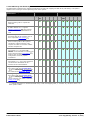
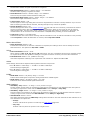
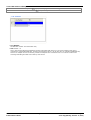
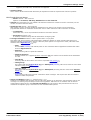
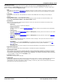
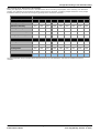
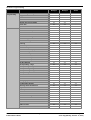
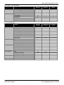
1.2.2.2 DID/Call-by-Call Summary
The table below summarizes the supported destinations for DID call mapping and SIP call-by-call settings. The options
depend on the trunk type and the operating mode of the system.
DID Call Mapping/SIP Call-by-Call
Destinations
Key Mode
Alog ETSI BRI
PRI
PRI
PBX Mode
T1
SIP
Alog ETSI BRI
PRI
· Extension
Route incoming calls to a particular
extension.
–
–
· Phantom Extension
IP Office Release 6.1+ supports
phantom extensions 22 . One of these
can be selected as the destination for
calls.
–
–
· Hunt Group
Incoming calls can be routed to one of
the 6 sequential hunt groups 77 .
–
–
· Voicemail
Route incoming calls to the systems
voicemail to collect messages. This
requires the caller to know the mailbox
number and passcode.
–
–
· 76: Modem
For Release 6.1+, the option 76:
Modem can be selected to route the call
to the systems built in V32 modem 23
function. This is intended for basic
configuration access by system
maintainers.
–
–
· Auto Attendant
For Release 6.1+, any of the configured
voicemail auto attendants can be
selected as the call destination.
–
–
· Operator Group
For systems with their System Mode
48 set to PBX System, incoming calls
are routed to the Operator Group 77 .
–
–
–
–
–
· Calling Group
For systems with their System Mode
48 set to PBX System, incoming calls
can be routed to one of the 4 collective
calling groups 77 .
–
–
–
–
–
–
–
–
*
*
PRI
T1
*
*
SIP
–
* = Default destination for fixed Default DID entry in DID Call Mapping table, ie. matches any call where there is no
other specific match.
IP Office Basic Edition - Quick Mode 8.1 FP1 Manager
IP Office Basic Edition
Page 16
- Issue 05g (Monday, October 15, 2012)
Telephony Features: Key System or PBX System
1.3 Dial Plan
Extension Numbering
The system can be configured to use either a 2 digit or 3 digit dial plan for user extensions.
· For a 2 digit dial plan, the extensions are numbered 10 to 57. This numbering cannot be changed.
· For a 3 digit dial plan, the extensions are numbered from 100 upwards. This numbering can be changed in the
range 100 to 579 (the defaults are 100 to 199). In 2 digit mode only 48 extensions are supported, in 3 digit mode
a maximum of 100 extensions are supported.
· In both cases, those extensions not matched by physical ports are automatically assigned as phantom extensions
22 .
· The system assumes that the base control unit is always fully populated with up to 32 extensions, either real or
phantom or a mix, to which it assigns extension numbers in sequence. It does this before assigning extension
numbers to any real extensions on attached external expansion modules up to the system extension limit. If the
system extension limit has not been exceeded, any remaining extension numbers are assigned to additional
phantom extensions.
IP Office Basic Edition - Quick Mode 8.1 FP1 Manager
IP Office Basic Edition
Page 17
- Issue 05g (Monday, October 15, 2012)
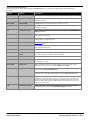
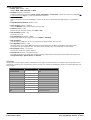
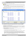
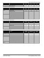
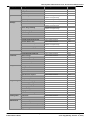
Special Dialed Numbers
The following can be dialed after selecting an Intercom button or simply going off hook (for which Intercom is
assumed).
Number
Function
Description
0
Operator
Calls the first extension in the system.
610 to 657
Extension Pickup
Answer the call alerting at another extension. Dial 6 followed by the
extension number.
661 to 664
Group Pickup
Dial 66 followed by the pickup group number (1 to 4).
6801-6864
Line Pickup
Answer the call alerting on a particular line. Dial 68 followed by the line
number (01 to 64).
70
Loudspeaker Page
Makes a call to the extension configured as the system's Loudspeaker
Paging extension.
71-74
Calling Group
Dial 7 followed by the calling group number (1 to 4). Prefix the number
with * to page the group.
75
Operator Group
This is supported only on systems with their Mode set to PBX. Prefix the
number with * to page the group.
76
Modem
Modem port
771 to 776
Hunt Group
Dial 77 followed by the hunt group number (1 to 6). Prefix the number
with * to page the group.
777
Voicemail Collect
Connects the extension to the extension user's own mailbox.
778
Remote Voicemail
Access
Connects the extension to prompts to specify the mailbox required. This
voicemail code of the mailbox is then requested.
7801 to 7809
Auto Attendant Access Call the auto attendant (1 to 9) specified.
801 to 864
Idle Line Pickup
Seize a line in order to then make a call on that line. Dial 8 followed by the
line number (01 to 64).
865 to 899
Seize a Line
Seize an available trunk in the ARS selector group (65 to 99). This is
supported only on systems with their Mode set to PBX.
9
External Call Prefix
Key: Start an outgoing external call. The line used is automatically
selected using Idle Line Preference.
23
. Used for remote access for configuration.
PBX: Optional external dialing prefix. The use of 9 can be removed or
swapped with 0 (the operator number) using the Outside Line setting.
*
Page/Direct Call
Putting * in front of an internal number will attempt to make either a page
or direct call. If the target is a group, the call is a page call to all the idle
members of the group. If the target is an extension, the call is an auto
answered call to that number. If the target cannot auto answer, the call
becomes a normal call.
*70
Simultaneous Page
Make a page call to the users in Calling Group 1 and to the extension
configured as the system's Loudspeaker Paging extension.
IP Office Basic Edition - Quick Mode 8.1 FP1 Manager
IP Office Basic Edition
Page 18
- Issue 05g (Monday, October 15, 2012)
Telephony Features: Dial Plan
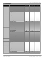
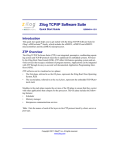
Auto Attendant Numbers
Dialing the appropriate number shown in the table below allows recording and playback of the matching auto attendant
prompt. It is important to remember that callers always hear two prompts, a greeting prompt and then a menu prompt.
In addition that may also hear the emergency greeting first if it has been activated.
Auto Attendant
Greeting Prompts
1
2
3
4
5
6
7
8
9
Morning Greeting
7811
7812
7813
7814
7815
7816
7817
7818
7819
Afternoon Greeting
7821
7822
7823
7824
7825
7826
7827
7828
7829
Evening Greeting
7831
7832
7833
7834
7835
7836
7837
7838
7839
Out of Hours Greeting
7851
7852
7853
7854
7855
7856
7857
7858
7859
Emergency Greeting
7861
7862
7863
7864
7865
7866
7867
7868
7869
Morning Menu
7841
7842
7843
7844
7845
7846
7847
7848
7849
Afternoon Menu
7871
7872
7873
7874
7875
7876
7877
7878
7879
Evening Menu
7881
7882
7883
7884
7885
7886
7887
7888
7889
Out of Hours Menu
7891
7892
7893
7894
7895
7896
7897
7898
7899
Auto Attendant Access
7801
7802
7803
7804
7805
7806
7807
7808
7809
Action Prompts
The Auto Attendant Access numbers allow internal access to an auto attendant. Calls can be transferred to these
numbers.
IP Office Basic Edition - Quick Mode 8.1 FP1 Manager
IP Office Basic Edition
Page 19
- Issue 05g (Monday, October 15, 2012)
1.4 Date and Time Setting
By default the system is configured to use network time synchronization using the first analog trunk on the card installed
in slot 1 of the system control unit. In that mode it gets its system time and date from the information that the line
provider includes as part of the caller ID information. When network time synchronization is being used, system in a
North American locale can also be configured to apply automatic daylight saving changes.
If the network time synchronization method above cannot be used on a particular system, it needs to be disabled. The
time and date are then set manually. This is all done using a system administrator phone 208 .
1.5 Voicemail Operation
All IP Office Basic Edition - Quick Mode systems include voicemail as standard. By default up to 2 calls can simultaneously
use voicemail services. By adding licenses, this can be increased up to 6 simultaneous calls.
When Do Calls Go To a User's Mailbox?
If a user has voicemail enabled (VMS Cover set to Enabled (the default)), calls directed to ring at that user's extension
go to the user's voicemail after having rung for the time set by the user's Voicemail Coverage Rings setting
(approximately 15 seconds by default). For incoming external calls, this will apply if the user is set as the line's
Coverage Destination.
· The above does not apply for calls altering just on a line appearance button that the user has assigned or alerting
the user as part of a hunt group.
· There are number of methods for a user to switch their VMS Cover setting on or off (through their mailbox,
through the phone menus, or using a VMS Cover 156 button)
· A VMS Transfer
157
button can be configured to let a user transfer calls directly to the mailbox of other users.
When Do Calls Go to an Auto Attendant?
The IP Office Basic Edition - Quick Mode voicemail supports the configuration of up to 9 auto attendant services to
answer and redirect calls. If an auto attendant has been configured, it can be used to answer calls as follows:
· Immediate Auto Attendant Service
One of the auto attendants can be specified as the Coverage Destination for a particular line. The call is
presented immediately to that auto attendant.
· Delayed/Optional Auto Attendant Service
The VMS Schedule setting of each line can be used to set whether unanswered calls should go to a selected auto
attendant. The settings can be enabled for day service, night service 21 , both or never (the default). The delay
used before going to the auto attendant is set by the line's VMS Delay - Day and VMS Delay - Night settings as
appropriate.
IP Office Basic Edition - Quick Mode 8.1 FP1 Manager
IP Office Basic Edition
Page 20
- Issue 05g (Monday, October 15, 2012)
Telephony Features: Voicemail Operation
1.6 Night Service
Use this feature to program a button on the first extension on the system to turn night service on and off. When night
service is on, all lines assigned to the telephones of the users in the night service group 77 ring immediately, regardless
of their normal line ringing settings.
Night service is useful if you want phones to ring after regular business hours. For example, although Shipping
Department workers do not answer calls directly during the day, you want them to answer incoming calls after hours.
· You must program a Night Service Button on the first extension on the system.
· This function is only supported on a button that includes LED/LCD indicator. The indicator is lit when the function is
enabled.
· If the user has this feature enabled, removing this button will turn the feature off.
· Dialing restrictions for extensions not in the Night Service Group remain the same as during normal daytime
operation.
· If you reassign the Night Service Button, it is removed from the button where it was previously assigned.
· If you program a System Password 48 , you must enter the password when turning Night Service on or off. In
addition, when Night Service is on, users in the Night Service Group can dial only numbers on the Emergency
Phone Number List 55 and marked system speed dial numbers without entering the System Password. Night
Service with a System Password is useful for controlling unauthorized use of phones after hours.
· If you have a voice messaging system, VMS Hunt Schedule determines when outside calls should ring voicemail.
The status of the Night Service Button tells the voice messaging system to operate in day or night mode.
· The Night Service Button returns to the status (on/off) it was in immediately prior to a power failure or to a
system reset 170 being used.
· Night Service is unavailable on T1 lines with Direct Inward Dialing (DID).
IP Office Basic Edition - Quick Mode 8.1 FP1 Manager
IP Office Basic Edition
Page 21
- Issue 05g (Monday, October 15, 2012)
1.7 Phantom Extensions
For Release 6.1 and higher, extension users are created in the system configuration for all users regardless of whether
they are matched by physical extension ports available. Those user extensions without a physical port are referred to as
'phantom' extensions.
The main purpose of phantom extensions is to provide voicemail mailboxes that are not associated with an existing
physical extension. These mailboxes can be accessed and used by the auto attendant menus and other functions.
· The system assumes that the base control unit is always fully populated with up to 32 extensions, either real or
phantom or a mix, to which it assigns extension numbers in sequence. It does this before assigning extension
numbers to any real extensions on attached external expansion modules up to the system extension limit. If the
system extension limit has not been exceeded, any remaining extension numbers are assigned to additional
phantom extensions.
The Manager application's menus and phone based administration menus allow selection of a phantom user extension
number in the same was as for normal physical extension numbers. Phantom extensions are indicated by # in front of
the extension number. That includes using a phantom extension as the destination in an auto attendant, trunk DID call
map, SIP call by call mapping, etc.
· Calls to a phantom extensions are treated as follows:
· Calls go immediately to the phantom user's voicemail mailbox. Forwarded or transferred calls go to the
mailbox of the user doing the transfer or forward.
· If the phantom extension is included in a hunt group, they are ignored.
· Callers can use the phantom user's mailbox DTMF breakout settings, if configured, to be transferred to another
destination.
· Calls can be transferred to a phantom extension. Since the calls go immediately to voicemail, no transfer return is
supported.
· Joining or bridging to a call that has been sent to a phantom extension’s mailbox will drop the phantom extension
from the call in the same way it does for a physical extension.
· Calls to a phantom extension cannot be picked up.
· The phantom extensions are supported within the auto attendant actions Dial by Name, Dial by Number and
Transfer to Number.
· Mailbox access for message collection and mailbox configuration is achieved by dialing 778 from any telephone,
then entering the phantom extension number and the mailbox access code if it has already been configured.
Mailboxes with a configured access code can also be accessed by external calls.
· Phantom extensions can be used as the line coverage extension for a line. In this case, the phantom extension's
VMS Coverage Rings setting is used before the call goes to the phantom user's mailbox.
· Auto Dial Intercom buttons can be set to route calls to a phantom extension.
· When using the Manager application, when selecting extensions in the various menus, a phantom extension is
indicated by a # character. The extensions Equipment Type is fixed as Phantom.
· The phantom extension's Automatic VMS Coverage setting can be used to disable mailbox operation. If this is
done, calls to the phantom extension will hear busy tone.
The following features are specifically are not supported using phantom extensions:
· A phantom extension cannot be configured as any other extension type, ie. loudspeaker, door phone, fax machine
or standard extension.
· A phantom extension cannot be configured as a night service alert extension.
· A phantom extension cannot be configured as a hotline extension.
· A phantom extension cannot be added to a hunt group, pickup group or calling group.
· A phantom extension specified as the destination for call forwarding or follow me is ignored. Instead calls will
continue to alert at the forwarded user.
· A phantom extension specified as the destination for another extension's call coverage is ignored. Instead calls will
continue to alert at the covered extension.
IP Office Basic Edition - Quick Mode 8.1 FP1 Manager
IP Office Basic Edition
Page 22
- Issue 05g (Monday, October 15, 2012)
Telephony Features: Phantom Extensions
1.8 One Touch Transfer
Release 6.1 and higher supports one touch transfer operation with a number of different button types. With a call
currently connected, the user can start the transfer process by pressing a button pre configured for the destination rather
than having to first press TRANSFER.
The button types that support this operation are listed below. Buttons programmed for voice or page calls can be used.
· Auto Dial ICM
· Auto Dial ICM - Page
· Group Calling - Ring
· Group Calling - Page
· Group Hunting - Ring
· Group Hunting - Page
· Simultaneous Page
1. With a currently connected call, the user starts the transfer by pressing the button programmed for the transfer
destination.
2. The system seizes an intercom button using the user's automatic line selection
are available, the button press is ignored.
65
setting. If no intercom buttons
3. When an intercom button is seized, the system puts the connected call on hold pending transfer and makes the
voice or page call to the transfer destination.
4. The user can switch between calls using the appropriate intercom and or line appearance for each call.
· If the transfer destination is busy then the transfer cannot be completed. The user should press the
appropriate appearance button for the held call to reconnect to the caller.
5. The user can complete the transfer by going on hook (replacing the handset, pressing SPEAKER or pressing
HEADSET depending on how they were handling the call being transferred) or pressing TRANSFER or selecting
the Complete soft key on the display.
· Calls transferred using one touch transfer are still subject to voicemail coverage or transfer return in the same way
as normal transferred calls.
· Using this feature and trying to complete a transfer to a door-phone, or a loudspeaker paging extension, is not
allowed. The transfer attempt is dropped and the original call remains on hold.
1.9 Modem Access Support
The first analog line port in any system can be used for V32 modem access. The line is switched between modem
operation and normal voice call operation by dialing *9000* or through the Modem Enabled option shown in the trunk's
advanced setup settings. When operating as a modem, the line cannot be used for normal voice calls.
For Release 6.1 and higher, the modem functionality can also be accessed as extension 76. This can be used as the
destination in an auto attendant menu in the DID mapping/SIP Call-by-Call tables of trunks. This allows remote access on
lines other than the first analog line.
Remote access requires entry of the user name and password used for IP Office Manager as the connection name and
password.
1.10 SIP Trunks
The IP Office Basic Edition - Quick Mode can support SIP trunks through its LAN connection. These are configured using
IP Office Manager, they cannot be managed through phone based administration.
In order to support SIP trunks, the system must include the following resources:
· SIP Trunk Licenses
These licenses are used to configure the number of simultaneous SIP trunk calls supported, up to a maximum of
20. A IP Office Basic Edition - Quick Mode system supports 3 channels without licenses.
· Voice Compression Channels
These are required to convert between the audio compression methods used for IP telephony and those used for
analog and digital trunks. Each IP500 Combination card (up to 2) installed in the system provides 10 voice
compression channels for the system. One voice compression channel is used for each SIP call.
IP Office Basic Edition - Quick Mode 8.1 FP1 Manager
IP Office Basic Edition
Page 23
- Issue 05g (Monday, October 15, 2012)
IP Office Basic Edition - Quick Mode 8.1 FP1 Manager
IP Office Basic Edition
Page 24
- Issue 05g (Monday, October 15, 2012)
Chapter 2.
The Manager Application
IP Office Basic Edition - Quick Mode 8.1 FP1 Manager
IP Office Basic Edition
Page 25
- Issue 05g (Monday, October 15, 2012)
2. The Manager Application
IP Office Manager is a Windows PC application used to configure Avaya IP Office telephone systems. This document
covers the use of Manager with IP Office Basic Edition - Quick Mode systems to load, edit and save the configuration of
those systems. The Configuration Settings 47 section covers details of the individual configuration settings accessible
using IP Office Manager.
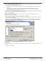
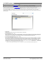
! Important: IP Office is an Offline Editor
When a system configuration is loaded into Manager, it is a configuration file copied to the Manager PC. Any changes
made to that configuration have no effect on the system until the copy is saved back to the system from the Manager
PC.
IP Office Basic Edition - Quick Mode 8.1 FP1 Manager
IP Office Basic Edition
Page 26
- Issue 05g (Monday, October 15, 2012)
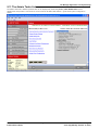
The Manager Application:
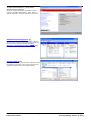
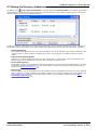
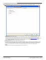
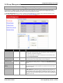
Manager Modes
The menus and options displayed by Manager vary depending on the actions you are performing. Manager can run in the
following modes.
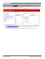
Simplified View
40
This is Managers default mode when no IP Office
configuration has been opened.
Advanced View
This mode can be selected instead of the Simplified
view when no configuration is loaded. It is not
normally used for IP Office Basic Edition - Quick Mode
systems and so is not covered by this document.
IP Office Configuration Mode
When the configuration from an IP Office system
running in IP Office Essential Edition is opened in
Manager, Manager displays options for that mode.
This mode is not covered by this document.
IP Office Basic Edition - Quick Mode 8.1 FP1 Manager
IP Office Basic Edition
Page 27
- Issue 05g (Monday, October 15, 2012)
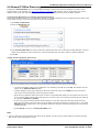
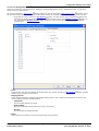
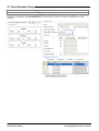
IP Office Basic Edition - Quick Mode
Configuration Settings
When the configuration from an IP Office system
running in IP Office Basic Edition - Quick Mode is
opened in Manager, Manager switches to this mode.
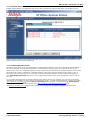
Embedded File Management
176
For systems with a memory card installed, Manager
can be used to view and manage the files stored on
the card. This is accessed through the File |
Advanced | Embedded File Management.. 176 . .
Upgrade Wizard
172
The Upgrade Wizard is a component of Manager used
to upgrade the firmware run by the control unit and
expansion modules within an IP Office system.
IP Office Basic Edition - Quick Mode 8.1 FP1 Manager
IP Office Basic Edition
Page 28
- Issue 05g (Monday, October 15, 2012)
The Manager Application:
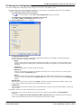
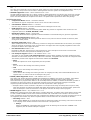
2.1 Installing Manager
The IP Office Administration suite consists of a number of applications for IP Office installers and
maintainers.
· o System Monitor - Install
· o Manager - Install
· o System Status Application - Install
· o Call Status - Optional
This software is not supported with IP Office Release 7.0 systems. It is provided only for the
maintenance of older systems.
Requirements
· o IP Office Administrator Applications DVD
Alternatively the IP Office Administrator Applications suite can be downloaded from Avaya's support website (
http://support.avaya.com).
· o Windows PC Requirements
This should meet the requirements of the administrator applications being installed. The specification below are
the minimum requirements for IP Office Manager. If other applications are to be installed on the PC then their
individual requirements should also be met.
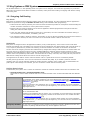
Requirement
Minimum
Recommended
Processor
600MHz Pentium or AMD Opteron, AMD
Athlon64, AMD Athlon XP.
800MHz Pentium or AMD Opteron, AMD
Athlon64, AMD Athlon XP.
RAM
128MB
256MB
HD Space
1GB - 800MB for .NET2, 200MB for Manager.
1.4GB - 800MB for .NET2, 600MB for the full
IP Office Admin suite.
Display
800 x 600 - 256 Colors
1024 x 768 - 16-bit High Color
Operating
System
Supported on Windows XP Pro, Windows Vista, Windows 7, Windows 2003 and Windows
2008.
· 32-bit and 64-bit versions are supported.
· Vista support is only on Business, Enterprise and Ultimate versions.
· Windows 7 support is only on Professional, Enterprise and Ultimate versions.
IP Office Basic Edition - Quick Mode 8.1 FP1 Manager
IP Office Basic Edition
Page 29
- Issue 05g (Monday, October 15, 2012)
Installing the IP Office Admin Applications
1. Using the Add or Remove Programs option in the Windows Control Panel, check that the PC does not already
have a version of the IP Office Admin suite installed.
· If 'yes' and the suite is a pre-IP Office 3.2 version, remove the existing IP Office Admin suite via Add/Remove
Programs.
· If the existing suite is IP Office 3.2 or higher, it is possible to upgrade without removing the previous
installation. However, if the system already has a USB Feature Key, the key should be removed prior to
upgrading and then reinserted and the PC restarted.
2. Insert the IP Office Administrator Applications DVD. Select the option for the IP Office Administration Suit. A folder
window will display the installation files for the administration suite.
3. Double-click on setup.exe.
4. Select the language you want to use for the installation process. This does not affect the language used by
Manager when running. Click Next >.
5. Select who should be able to run the Admin Suite applications. Click Next >.
6. If required select the destination to which the applications should be installed. We recommend that you accept the
default destination. Click Next >.
7. The next screen is used to select which applications in the suite should be installed. Clicking on each will display a
description of the application. Click on the
next to each application to change the installation selection. When
you have selected the installations required, click Next >.
8. Ensure that at minimum System Monitor and Manager are selected. Click Next >.
9. Click Install.
10.Installation of Windows .Net2 components may be required. If menus for this appear, follow the prompts to install
.Net.
11.If requested, reboot the PC.
IP Office Basic Edition - Quick Mode 8.1 FP1 Manager
IP Office Basic Edition
Page 30
- Issue 05g (Monday, October 15, 2012)
The Manager Application: Installing Manager
2.2 Starting Manager
1. Select Start | Programs | IP Office | Manager.
· If the PC has firewall software installed, you may be prompted as to whether you want to allow this program
to access the network. Select Yes or OK.
2. When the Manager application starts, it briefly displays a splash screen. It will then perform several possible
actions: and then presents the welcome screen.
3. By default the application will automatically scans the local network for an IP Office system. This behavior can be
disabled in the Manager application preferences 161 in which case the default welcome page is displayed (see
Simplified View 40 ).
a. If only one system is found and it is current Administrator account password is password, Manager will
automatically load and display the configuration from that system.
b. If only one system is found but its administrator password is not set to password, the menu for entering the
valid name and password is displayed.
c. If several systems are found, the Select IP Office menu is displayed. Use this menu to select which system
to load. For details of adjusting the Select IP Office menu see Setting the Discover Address 33 .
IP Office Basic Edition - Quick Mode 8.1 FP1 Manager
IP Office Basic Edition
Page 31
- Issue 05g (Monday, October 15, 2012)
d. If no system is found or an invalid name and password are used, then the Manager simplified view
Welcome menu is displayed.
IP Office Basic Edition - Quick Mode 8.1 FP1 Manager
IP Office Basic Edition
40
Page 32
- Issue 05g (Monday, October 15, 2012)
The Manager Application: Starting Manager
2.3 Setting the Discovery Addresses
By default, when
or File | Open configuration is selected, Manager's Select IP Office menu appears. It performs a
UDP broadcast to the address 255.255.255.255. This broadcast will only locate IP Office systems that are on the same
network subnet as the PC running IP Office Manager.
The process above is called discovery. A UDP broadcast will not be routed to other networks and subnets. Therefore to
find IP Office systems not located on the same subnet as the Manager PC, the following other options are supported.
· Specific Addressing
The Unit/Broadcast Address shown on the Select IP Office menu can be changed to the specific IP address of the
required system. A single address is routable and so can be used to discover an IP Office system on another
subnet.
· TCP Discovery Address Ranges
IP Office 3.2+ systems support discovery by TCP as well as UDP. To support this, a set of TCP addresses and
address ranges can be specified for use by the Select IP Office discovery process.
· Known Units Discovery
The IP Office 4.0 Q2 2007 maintenance release adds supports for a system whereby IP Office Manager can write
the details of systems it discovers to a file. The list of systems in that file can then be used for access to those
systems. See Known Units Discovery 35 .
· DNS Lookup
IP Office Manager 6.2 can be configured to locate IP Office systems using DNS name lookup. This requires the IP
Office systems on a customer network to be added as names on the customer's DNS server and the Manager PC
to be configured to use that server for DNS name resolution. The use of DNS is configured through File |
Preferences | Discovery 164 .
IP Office Basic Edition - Quick Mode 8.1 FP1 Manager
IP Office Basic Edition
Page 33
- Issue 05g (Monday, October 15, 2012)
Changing the Initial Discovery Settings
The Discovery tab of the Manager Preferences menu can be used to set the UDP and TCP addresses used by the
discovery process run by the Select IP Office menu.
1. Select File | Preferences menu.
2. Select the Discovery tab.
3. Under UDP Discovery you can enter the default UDP broadcast address to be used by the discovery process.
4. In the IP Search Criteria box you can enter IP addresses and IP address ranges for TCP discovery. Addresses
should be separated by semi-colons, ranges by - dashes.
IP Office Basic Edition - Quick Mode 8.1 FP1 Manager
IP Office Basic Edition
Page 34
- Issue 05g (Monday, October 15, 2012)
The Manager Application: Setting the Discovery Addresses
2.4 Known IP Office Discovery
The Manager Select IP Office menu normally displays IP Office systems discovered by Manager using either UDP
broadcast and or TCP requests (see Setting the Discovery Addresses 33 ). Manager can be configured to also record
details of discovered units and then display a list of those previously discovered ('known') IP Office systems.
Configuring Manager for Known System Discovery
Use of known systems discovery is not enabled by default. The IP Office Manager must be configured for the feature with
a file location to which it can store and retrieve known system details.
1. Select File | Preferences.
2. Select the Directories tab.
3. In the Known Units File field, enter the directory path and file name for a CSV file into which Manager can write
details of the IP Office systems it discovers. If the file specified does not exist it will be created by Manager.
4. Click OK.
Using Known System Discovery
1. When the Select IP Office screen is displayed click on Known Units.
2. The screen displays the list of IP Office systems previously discovered and stored in the CSV file.
· To select an IP Office control unit, highlight the row containing unit data and click OK. The selected unit will
appear in the Select IP Office window.
· To filter displayed units, type the first few characters of the unit name in the Filter field. Any unit whose
name does not match the filter will be temporarily hidden.
· Each discovery appends data to the known unit list. It is possible that details of some entries in the list may
be out of date. Right clicking on the leftmost (grey) column of any row will bring up a floating menu offering
the options of Refresh and Delete.
· A new entry may be manually added without having to access the system first through normal discovery.
Enter the IP address of the new system in the IP Address column of the blank row shown with a * and select
Refresh from the floating menu. This will update the Known Units file with data relating to the unit with the
specified address.
· Select Cancel to return to the Select IP Office menu.
Note:
· The key used by the Known Systems CSV file is the IP address. The file cannot contain entries for separate systems
that use the same IP address for access.
IP Office Basic Edition - Quick Mode 8.1 FP1 Manager
IP Office Basic Edition
Page 35
- Issue 05g (Monday, October 15, 2012)
· The file can be made read only. In that case any attempts using Manager to update the file will be ignored.
IP Office Basic Edition - Quick Mode 8.1 FP1 Manager
IP Office Basic Edition
Page 36
- Issue 05g (Monday, October 15, 2012)
The Manager Application: Known IP Office Discovery
2.5 Saving the Configuration
The current configuration settings open within Manager can be sent to the IP Office system.
1. The first steps of this process depend on whether you are sending a configuration received from the IP Office
system or sending one opened offline/created new.
· A Configuration Opened from an IP Office
Click
in the main toolbar or select File | Save Configuration from the menu bar.
· A Configuration Created Offline or Opened from a PC File
Select File | Offline | Send Config from the menu bar.
2. The Send Configuration menu is displayed.
· Configuration Reboot Mode
If Manager thinks the changes made to the configuration settings are mergeable, it will select Merge by
default, otherwise it will select Immediate.
· Merge
Send the configuration settings without rebooting the IP Office. This option is selected by default if the
changes made since the configuration was loaded into Manager as mergeable, do not select this option
otherwise.
· Immediate
Send the configuration and then reboot the IP Office.
· When Free
Send the configuration and reboot the IP Office when there are no calls in progress. This mode can be
combined with the Call Barring options.
· Timed
The same as When Free but waits for a specific time after which it then wait for there to be no calls in
progress. The time is specified by the Reboot Time. This mode can be combined with the Call Barring
options.
· Reboot Time
This setting is used when the reboot mode Timed is selected. It sets the time for the IP Office reboot. If the
time is after midnight, the IP Office's normal daily backup is canceled.
· Call Barring
These settings can be used when the reboot mode When Free is selected. They bar the sending or receiving of
any new calls.
3. Click OK. A Service User name and password may be requested.
· If the service user name or password used do not have a match on the IP Office, "Access Denied" is
displayed.
· The message Failed to save the configuration data. (Internal error) may indicate that the system has
booted using software other than that in its System SD card's primary folder.
IP Office Basic Edition - Quick Mode 8.1 FP1 Manager
IP Office Basic Edition
Page 37
- Issue 05g (Monday, October 15, 2012)
IP Office Basic Edition - Quick Mode 8.1 FP1 Manager
IP Office Basic Edition
Page 38
- Issue 05g (Monday, October 15, 2012)
The Manager Application: Saving the Configuration
2.6 Saving a Configuration to a PC File
The IP Office configuration settings shown within Manager can be saved to a .cfg file on the Manager PC. These files can
be used as backups.
Automatically Saving Configuration Copies
By default, Manager creates a file copy of the configuration before it is sent to the IP Office system. This copy is stored in
Manager's Working Directory 163 using the IP Office's system name and .cfg. This behavior is controlled by the Backup
File on Send (File | Preferences | Security) 166 option.
Saving a Configuration Received from an IP Office
1. Select File | Save Configuration as from the menu bar.
Saving a Configuration opened on the PC
1. Click
in the main toolbar or select File | Save Configuration from the menu bar.
2.7 Loading a PC File
Configuration files previously saved onto the PC can be reloaded into Manager. Select File | Offline | Open File or from
the default simplified view select Read a Configuration from File.
In order to send that configuration to a system the File | Offline | Send Config command must be used.
·
A configuration created offline should only ever be loaded to a system with the matching hardware
configuration. Doing otherwise may cause system faults.
IP Office Basic Edition - Quick Mode 8.1 FP1 Manager
IP Office Basic Edition
Page 39
- Issue 05g (Monday, October 15, 2012)
2.8 Simplified View
This is the default view displayed by Manager when it doesn't have a system configuration loaded.
The screen provides three main actions:
· Create an Offline Configuration 44
Create an IP Office Basic Edition - Quick Mode configuration by selecting from a menu of hardware options. That
configuration can then be saved as a file on the PC or uploaded to a system.
· Open Configuration from System 31
Restarts the process used by Manager to locate an IP Office system and load its configuration.
· Read a Configuration from File
Load a configuration that has been saved as a file on the PC.
Manager can be switched from simplified view to advanced view by selecting View | Advanced View. The advanced
view is not normally used with IP Office Basic Edition - Quick Mode systems and so is not covered by this manual.
Whether Manager uses simplified view or advanced view when it has no configuration loaded is set by the Manager
preferences 161 setting Set Simplified View as default.
IP Office Basic Edition - Quick Mode 8.1 FP1 Manager
IP Office Basic Edition
Page 40
- Issue 05g (Monday, October 15, 2012)
The Manager Application: Simplified View
2.9 Advanced View
This view is used by IP Office Manager for the administration of standard IP Office systems. It is not used for the
administration of IP Office Basic Edition - Quick Mode systems.
If Manager is running in this mode, you can return to simplified view by selecting View | Simplified View. Alternatively
you can use the advanced view to load a configuration. The Manager will automatically return to simplified view mode
when an IP Office Basic Edition - Quick Mode configuration is loaded.
IP Office Basic Edition - Quick Mode 8.1 FP1 Manager
IP Office Basic Edition
Page 41
- Issue 05g (Monday, October 15, 2012)
2.10 The System Page
This is the default or home page when an IP Office Basic Edition - Quick Mode configuration has been loaded into IP
Office Manager. It displays a summary of the system and a list of links for common configuration tasks.
IP Office Basic Edition - Quick Mode 8.1 FP1 Manager
IP Office Basic Edition
Page 42
- Issue 05g (Monday, October 15, 2012)
The Manager Application: The System Page
2.11 The Admin Tasks List
The Admin Tasks list is hidden by default but can be displayed by deselecting View | Hide Admin Tasks. When
displayed the list provides a set of links to access all of the IP Office Basic Edition - Quick Mode system configuration
menus.
IP Office Basic Edition - Quick Mode 8.1 FP1 Manager
IP Office Basic Edition
Page 43
- Issue 05g (Monday, October 15, 2012)
2.12 Creating a Configuration File
Manager can be used to create a configuration file for a system.
·
A configuration created offline should only ever be loaded to a system with the matching hardware
configuration. Doing otherwise may cause system faults.
· Once the system has been installed, changing the order or combination of cards will require the system
configuration to be defaulted.
1. Close any current configuration open in Manager.
2. Select Create an Offline Configuration or File | Offline | Create New Config.
3. Check that the Configuration setting is set to IP Office Quick Mode.
4. Select the System Mode required. The options are Key or PBX. For more details see Key System or PBX
System 11 .
· Key System
The Number of Lines setting (see below) is used to automatically assign line appearance buttons on all
extensions with programmable buttons. To make external calls the user should select an available line
appearance button. Outbound call routing is determined by which line appearance button the user selects
before dialing or by the user's automatic line selection 65 settings.
· PBX System
No line appearances are automatically assigned. The Outside Line setting (see below) is used to set the
dialing prefix that indicates that the call is an external one for which an available line should be seized. The
Outbound Call Handling 122 settings are used to determine which lines are used for each outgoing call. Line
appearance buttons can also still be configured for making and answering external calls.
5. Set the Locale to match the default locale and language that should be used for the system. This will also affect
the extension and daughter cards available for selection in the following steps. Changing the locale will cause any
existing hardware selections to be cleared.
IP Office Basic Edition - Quick Mode 8.1 FP1 Manager
IP Office Basic Edition
Page 44
- Issue 05g (Monday, October 15, 2012)
The Manager Application: Creating a Configuration File
· The options are Argentina, Australia, Bahrain, Belgium, Brazil, Canada, Chile, China, Customize,
Denmark, Egypt, Finland, France, Germany, Greece, Hong Kong, Hungary, Iceland, India, Italy,
Korea, Kuwait, Mexico, Netherlands, New Zealand, Norway, Oman, Pakistan, Peru, Poland,
Portugal, Qatar, Russia, Saudi Arabia, Singapore, South Africa, Spain, Sweden, Switzerland,
Taiwan, Turkey, United Arab Emirates, United States, Venezuela.
6. Select the extension number length that should be used, the options are 2 or 3.
7. In the Select Extension and Daughter Cards section, select the cards that match those in the system to which
the configuration will be loaded.
· Ensure that these match the actual physical positions of the cards that are or will be installed in the system. If
the arrangement of cards needs to be changed at a later date, it may require the whole configuration to be
deleted.
· For system administration through the first two extensions, the card in slot 1 must support Avaya digital
phones, ie. a Dig Sta 8, Combo DS6 or ETR6.
· The ETR6 extension card is only selectable for systems with a United States, Canada or Mexico locale.
· BRI trunk cards are not selectable for systems with a United States, Canada or Mexico locale.
8. Use the Expansion Modules box to select the expansion module if there are any attached to the system to which
the configuration will be loaded.
9. When the hardware selection is as required, click OK.
10.The configuration is now created and loaded into Manager for editing.
11.Once this configuration has been edited as required it can be saved on the PC or sent to a system.
a. To Save a Configuration File on the PC
Use File | Save Configuration.
b. To Send the Configuration to a System
If the system which you want to use the configuration is available, use File | Offline | Send Configuration
169 to send the configuration to it.
·
! WARNING: This action will cause the system to reboot and will disconnect all current calls and service.
· Ensure that you have a copy of the systems existing configuration before overwriting it with the off-line
configuration.
· After sending the configuration, you should receive the configuration back from the system and note any
new validation errors shown by Manager. For example, if using Embedded Voicemail, some sets of prompt
languages may need to be updated to match the new configurations locale setting using the Add/
Display VM Locales 179 option.
IP Office Basic Edition - Quick Mode 8.1 FP1 Manager
IP Office Basic Edition
Page 45
- Issue 05g (Monday, October 15, 2012)
Chapter 3.
Configuration Settings
IP Office Basic Edition - Quick Mode 8.1 FP1 Manager
IP Office Basic Edition
Page 46
- Issue 05g (Monday, October 15, 2012)
Configuration Settings:
3. Configuration Settings
This section details the IP Office Basic Edition - Quick Mode configuration settings accessible through IP Office Manager.
3.1 Remote/Administrator Password
This menu is accessed from the System
42
page by selecting Remote / Administrator Password.
This menu cannot be accessed from the Admin Tasks
43
.
New systems use default security settings with the user name Administrator and password Administrator. This is the
password used by IP Office Manager for access to a system. As a minimum, you should change the Remote/
Administrator Password. Failure to do so will leave the system potentially insecure.
This password is also used for connection to the system by the Administrator account to System Status Application,
System Monitor and IP Office Web Manager.
This command is greyed out and disabled when editing an off-line configuration.
Changing the Remote / Administration Password
1. From the Manager home page, click Change Remote/Administrator Password.
2. The Change Password menu is displayed.
3. Enter the new password, confirm it and click OK.
4. Click Apply in the system page or click on the
icon.
5. In the Send Configuration menu click OK.
6. The user name and password will be requested. Enter Administrator and the old password.
IP Office Basic Edition - Quick Mode 8.1 FP1 Manager
IP Office Basic Edition
Page 47
- Issue 05g (Monday, October 15, 2012)
3.2 System Settings
This menu is accessed from the System
42
page by selecting Change System Settings.
This menu is accessed from the Admin Tasks
43
list by selecting System.
This window displays a summary of the hardware components installed in the phone system. It also enables configuration
of system-specific settings.
Installed Hardware
This section displays a list of the hardware components (control unit and its base cards) for trunks and extensions that
are installed in the telephone system. These values are for information only and cannot be edited.
IP Office Basic Edition - Quick Mode 8.1 FP1 Manager
IP Office Basic Edition
Page 48
- Issue 05g (Monday, October 15, 2012)
Configuration Settings: System Settings
System Parameters
This section is used to configure the following system settings.
· System Name
A name used to identify the system. This is typically used to identify the configuration by the location or
customer's company name. Some features require the system to have a name. This field is case sensitive. Do not
use <, >, |, \0, :, *, ?, . or /.
· System Mode:
IP Office Basic Edition - Quick Mode systems can operate in either Key System or PBX System mode. For more
details see Key System or PBX System 11 . Changing the mode requires the IP Office system to be restarted and
will overwrite button programming.
· Key System
The Number of Lines setting (see below) is used to automatically assign line appearance buttons on all
extensions with programmable buttons. To make external calls the user should select an available line
appearance button. Outbound call routing is determined by which line appearance button the user selects
before dialing or by the user's automatic line selection 65 settings.
· PBX System
No line appearances are automatically assigned. The Outside Line setting (see below) is used to set the
dialing prefix that indicates that the call is an external one for which an available line should be seized. The
Outbound Call Handling 122 settings are used to determine which lines are used for each outgoing call. Line
appearance buttons can also still be configured for making and answering external calls.
· Voicemail Mode: Default = Intuity Mode. Software level = 8.0+.
Embedded voicemail can use either IP Office Mode or Intuity Mode key presses for mailbox functions. End
users should be provided with the appropriate mailbox user guide for the mode selected. Pre-Release 8.0 systems
use IP Office Mode only.
· Add/Display VM Locales: Software level = Release 8.0+.
For new IP500 V2 SD cards and cards recreated using IP Office Manager, the following Embedded Voicemail
languages set are placed onto cards by default. Using this option displays the list of languages that can be
uploaded from IP Office Manager. Those languages already present or not supported are greyed out. If a
locale is selected for the system, a user, a short code or an incoming call route which is not present on the SD
card, IP Office Manager will display an error. This command can be used to upload the required language
prompts to correct the error.
· IP Office A-Law/Norstar SD Cards: UK English.
· IP Office U-Law/PARTNER SD Cards: US English.
· Country:
This option sets a range of country specific telephony settings. It also sets the default language (shown in
brackets) used on phone displays and for voicemail prompts. If the setting is changed it will cause the settings of
all users and auto attendants to change to match. The system language can be changed from the Country setting
using the separate Language setting below.
· The options are Argentina, Australia, Bahrain, Belgium, Brazil, Canada, Chile, China, Customize,
Denmark, Egypt, Finland, France, Germany, Greece, Hong Kong, Hungary, Iceland, India, Italy,
Korea, Kuwait, Mexico, Netherlands, New Zealand, Norway, Oman, Pakistan, Peru, Poland,
Portugal, Qatar, Russia, Saudi Arabia, Singapore, South Africa, Spain, Sweden, Switzerland,
Taiwan, Turkey, United Arab Emirates, United States, Venezuela.
· When Default is selected, the following additional fields are available:
· Tone Plan: Default = Tone Plan 1
Select a tone plan to be used for different ringing signals such as dial tone and ring tone.
· CLI Type: Default = FSK V23
Set the method for passing caller ID information to analog extensions. The options are DTMF, FSK Bell
202 or FSK V23.
· Busy Tone Detection: Default = Off
Enable or disable the use of busy tone detection for call clearing.
·
! WARNING
Changing the system language requires the system to be rebooted when the changes are sent back to the
system.
· For each user, their language settings can be changed using the user's Language
language used on their phone's display and for mailbox access prompts.
61
setting. This affects the
· For each auto attendant, the system language setting can be overridden by the auto attendant's own
Language 132 setting.
· Receive IP Address Via DHCP Server: Default = On
When selected, the telephone system acts as a DHCP client and will obtain its IP address details by making DHCP
requests when started. If not selected, the telephone system uses the IP address set in the fields below.
IP Office Basic Edition - Quick Mode 8.1 FP1 Manager
IP Office Basic Edition
Page 49
- Issue 05g (Monday, October 15, 2012)
· IP Address: Default = 192.168.42.1
Enter the IP address that the telephone system should use if Receive IP Address Via DHCP Server is not
selected.
· Sub-Net Mask: Default = 255.255.255.0
Enter the Sub-Net Mask that the telephone system should use if Receive IP Address Via DHCP Server is
not selected.
· Default Gateway: Default = 0.0.0.0
Enter the Default Gateway that the telephone system should use if Receive IP Address Via DHCP Server
is not selected.
· Automatic Daylight Saving Time: Default = On.
When selected, the telephone system will automatically apply daylight saving time adjustments to its internal
clock. This feature should only be used for systems in a North American locale.
· Language
The default system language is normally set by the system's Country selection above (indicated in brackets after
the country name). However, this field can be used to change the system language if required. When used, it sets
the language used for voicemail prompts and phone displays if the language is available. The language settings
can also be set separately for each user 61 and for each auto attendant 132 service.
· The options are Arabic, Brazilian Portuguese, Canadian French, Cantonese, Danish, Dutch, Finnish,
French, German, Italian, Korean, Mandarin, Norwegian, Portuguese, Russian, Spanish, Spanish
(Argentinean), Spanish (Latin), Spanish (Mexican), Swedish, UK English, US English.
· If the upgraded set of prompts for the language selected are not available on the system, IP Office Manager
will display a warning. The Add/Display VM Locales 179 command can be used to upload the prompts from
IP Office Manager to the system.
· Number of Lines: Default = 5 or, if installed, the number of analog trunks when the system is first started.
This option is only available for systems with their System Mode (see above) set to Key System. For phones
with programmable buttons, those buttons can be configured as line appearance buttons that each match a
particular incoming line. This setting controls how many of buttons on every user's phone are automatically
allocated as line appearance buttons. The assignment is done starting from button 03 upwards in order of the lines
available.
·
! Warning
If this value is changed, all existing line appearance buttons and automatic line selection 65 settings are
overwritten. The existing functions on other programmable buttons are also overwritten if they are in the
range of buttons now specified for lines.
· Outside Line: Default = Depend on system locale, see below.
This option is only available for systems with their System Mode (see above) set to PBX System. It sets the
digit which, when dialed, indicates that the call is intended to be external. Routing of any additional digits is then
determined through the Outbound Call Handling 122 settings.
· 9 (Operator is 0)
The prefix 9 is used for external calls. The digit 0 is used for calls to the operator extension (the first
extension in the system). This is the default setting for systems with the Country setting United States.
· None
No prefix is used for external calls. Any dialing that does not match an internal dial plan number 17 is
assumed to be an external call. This is the default setting for systems with the Country setting other then
Germany or United States.
· 0 (Operator is 9)
The prefix 0 is used for external calls. The digit 9 is used for calls to the operator extension (the first
extension in the system). This is the default setting for systems with the Country setting Germany.
· System Password: Default = Blank. Range = 4 digits.
This is a four digit code used to restrict access to some functions. Once set, the system password must be used to
override station lock, forced account or disallowed calls list or night service outward restrictions to make a call.
The system password is also requested when a user switches the phone system into or out of night service mode
or tries to access an voicemail auto attendant's emergency greeting settings.
· For M-Series and T-Series phones, the system password, if set, is also used to control access to phone based
administration from the first two extensions in the system.
· Log All Caller ID Calls for Users: Default = None selected.
All extensions have a call log of their last 30 calls (incoming answered and missed). The user can access this using
a programmable button set to Call Log or their phone's Call Log button if it has one. In addition up to 3 extensions
can be configured to have access to the call log of the last 400 calls (incoming answered and missed) for the
whole system. These fields are used to select those users. Only calls that include caller ID are included. The !
character on the phone display indicates that there are unviewed call details in the call log.
IP Office Basic Edition - Quick Mode 8.1 FP1 Manager
IP Office Basic Edition
Page 50
- Issue 05g (Monday, October 15, 2012)
Configuration Settings: System Settings
· Unsupervised Analog Trunk Disconnect Handling: Default = Off. Software level = 8.0+
When using analog trunks, various methods are used for trunk supervision, ie. to detect when the far end of the
trunk has disconnected and so disconnect the local end of the call. Depending on the locale, the IP Office uses
Disconnect Clear signalling and or Busy Tone Detection 142 . This setting should only be enabled if it is known that
the analog trunks do not provide disconnect clear signalling or reliable busy tone. When enabled:
· Disconnect clear signalling detection is turned off. Busy tone detection remains on.
· Unsupervised transfers and trunk-to-trunk transfers of analog trunk calls are not allowed.
· A wider range of busy tones which may signal that the caller has disconnected are used to disconnect calls
connected to voicemail.
IP Office Basic Edition - Quick Mode 8.1 FP1 Manager
IP Office Basic Edition
Page 51
- Issue 05g (Monday, October 15, 2012)
3.2.1 List Management
This menu is accessed from the System
42
page by selecting Create Calling Lists.
This menu is accessed from the Admin Tasks
43
list by selecting System | List Management.
Calling lists control the numbers user can or cannot dial. You can also indicate which lists a user belongs to through the
User Setup 61 menu.
After highlighting the item you want to move, use the Add or Remove buttons to move users to and from the Selected
Users list . The different types of Calling list are:
List Type
Allowed Lists
Description
Sets numbers that associated users can dial even when call restrictions are
applied. 8 lists of 10 numbers.
53
Disallowed Lists
Sets numbers that associated users cannot dial. 8 lists of 10 numbers.
54
Emergency Number List
Account Code Entries
56
55
Sets up to 10 numbers that override all dialing restrictions at all times.
Sets up to 99 accounts codes and which users are required to enter an account
code when making external calls.
IP Office Basic Edition - Quick Mode 8.1 FP1 Manager
IP Office Basic Edition
Page 52
- Issue 05g (Monday, October 15, 2012)
Configuration Settings: System Settings
3.2.1.1 Allowed Lists
This menu is accessed from the System
42
page by selecting Create Calling Lists | Allowed Lists.
This menu is accessed from the Admin Tasks
43
list by selecting System | List Management | Allowed Lists.
Each allowed list contains external telephone numbers that members of the list are allowed to dial regardless of any other
call barring. The users allowed lists override any disallowed lists 54 of which they are also member and the user's
Outgoing Call Bar 61 and Outgoing Call Restrictions 72 settings.
There are eight lists, each containing up to 10 numbers. Each number can use the telephone dialing digits 0 to 9, *, #
and can be up to 28 digits long. You can also use the ? character as a single digit wildcard.
IP Office Basic Edition - Quick Mode 8.1 FP1 Manager
IP Office Basic Edition
Page 53
- Issue 05g (Monday, October 15, 2012)
3.2.1.2 Disallowed Lists
This menu is accessed from the System
42
page by selecting Create Calling Lists | Disallowed Lists.
This menu is accessed from the Admin Tasks
43
list by selecting System | List Management.
Each disallowed list contains external telephone numbers that users who are members of the list are not allowed to dial.
Numbers in the disallowed lists of which a user is a member are overridden if they also appear in the allowed numbers
lists, emergency number list of which the user is a member and also by marked system speed dials 57 .
There are eight lists, each containing up to 10 numbers. Each number can use the telephone dialing digits 0 to 9, *, #
and can be up to 28 digits long. You can also use the ? character as a single digit wildcard.
IP Office Basic Edition - Quick Mode 8.1 FP1 Manager
IP Office Basic Edition
Page 54
- Issue 05g (Monday, October 15, 2012)
Configuration Settings: System Settings
3.2.1.3 Emergency Number List
This menu is accessed from the System
42
page by selecting Create Calling Lists | Emergency Number Lists.
This menu is accessed from the Admin Tasks
43
list by selecting System | List Management.
You can enter 10 emergency phone numbers into this list. This list is applied to all users and overrides any dialing
restrictions that may also be applied to the users.
By default 911 is already added to the emergency list and cannot be removed.
IP Office Basic Edition - Quick Mode 8.1 FP1 Manager
IP Office Basic Edition
Page 55
- Issue 05g (Monday, October 15, 2012)
3.2.1.4 Account Code Entries
This menu is accessed from the System
42
page by selecting Create Calling Lists | Account Code Entries.
This menu is accessed from the Admin Tasks
43
list by selecting System | List Management.
Account codes are commonly used to control cost allocation and out-going call restriction. The account code used on a
call is included in the call information output by the system call log. Users can enter an account code during a call using
an Account Code Entry 66 button. Once a user has entered an account code with a call, only that user can change that
calls account code by entering another one.
Once a call has been completed using an account code, the account code information is removed from the user's call
information. This means that redial functions will not re-enter the account code.
Extensions can be required to enter a valid account code when they make an outgoing external call. The Account Code
Entries list contains the account codes that are accepted as being valid and the selected users who are required to enter
one of these codes, ie. the users who are set to Forced Account Code Entry.
All users (except analog phones) can also enter voluntary account codes at any time during a call by using an Account
Code Entry button. Voluntary account codes are recorded in the same way as forced account codes but are not
validated.
Using the Assign Users to List menu to add or remove users from the Selected User list will enable/disable the
Forced Account Code Entry 72 setting for the appropriate users.
IP Office Basic Edition - Quick Mode 8.1 FP1 Manager
IP Office Basic Edition
Page 56
- Issue 05g (Monday, October 15, 2012)
Configuration Settings: System Settings
3.2.2 Speed Dial Setup
This menu is accessed from the System
42
page by selecting Administer Speed Dial.
This menu is accessed from the Admin Tasks
43
list by selecting System | Speed Dial Setup.
This menu allows you to configure names and numbers that can be accessed by dialing the associated speed dial code,
600 to 699.
· For analog telephone devices, when using last number redial, saved number redial, system speed dial and
personal speed dial features no dial tones for the digits dialed are played to the caller.
IP Office Basic Edition - Quick Mode 8.1 FP1 Manager
IP Office Basic Edition
Page 57
- Issue 05g (Monday, October 15, 2012)
Speed Dials Configured
· Filter
This option allows you to show only speed dial entries where the name, number or speed dial code matches the
filter value entered. If there are no matches the whole set of speed dial entries is displayed.
· Import
Allows you to import a CSV text file of speed dials. Each line of the file should contain a name, number and speed
dial code, each separated by a comma. If an entry being imported matches an existing name it will overwrite the
existing entry. If an entry being imported matches an existing speed dial code, it will be assigned an unused speed
dial code.
Head Office, 555123456, 600
Acme, 555654321, 601
· Export
This control allows you to export a CSV text file of speed dials. You can then edit the file using a text editor.
· Comma Separated Variable text Files (. c s v)
These are plain text files. In addition to being exported from Manager these files can be created and edited
using programs such as WordPad. Manager imports and exports CSV files using UTF-8 character encoding
which uses a double byte to support characters with diacritic marks such as ä. Other applications, such as
Excel, may, depending on the user PC settings, use different encoding which will cause such characters to be
removed or corrupted. Care should be taken to ensure that any tool used to create or edit the CSV supports
all the characters expected and uses UTF-8 format.
· Exporting from Manager to Excel
Do not double-click on the file exported from Manager. Start Excel and use File | Open to select the file.
Excel will recognize that the file uses UTF-8 encoding and start its text file importation wizard. Follow the
wizard instructions and select comma as the field delimiter.
· Speed Dial Entries
For each speed dial entry in the menu, the following values are used:
· Name
This is the name that will be associated with the speed dial.
· Number
This is the external number that will be dialed by the telephone system when the speed dial code is dialed by
an extension user.
· Speed dials beginning with * are called 'marked speed dials' and are treated differently. A user can use a
marked speed dial even if the number is in a disallowed list of which the user is a member. Marked speed
dials can also be used when an extension is locked. When dialed, the * is not included. If a * is required
to be dialed, the speed dial should be start with **.
· For PBX mode systems, if the system is configured to use an Outside Line 48 prefix for outgoing
external calls, that prefix should be included in external speed dial numbers.
· Speed Dial Code
Select a number between 600 and 699. Each number can only appear once in the list. This is the short form
substitute number for often-used long numbers.
IP Office Basic Edition - Quick Mode 8.1 FP1 Manager
IP Office Basic Edition
Page 58
- Issue 05g (Monday, October 15, 2012)
Configuration Settings: System Settings
3.2.3 License Management
This menu cannot be accessed from the System
This menu is accessed from the Admin Tasks
43
42
page.
list by selecting System | License Management.
This menu is used to enter licenses required for additional telephone system features. For example licenses are used to
enable additional voicemail ports.
Each license is a unique 32-character string based on the feature being licensed and the serial number of the SD card
plugged into the system control unit. It is recommended that you use the Import control to import licenses. Alternatively
the license keys can be cut and pasted into the Key field. Entering licenses manually is liable to errors caused by
miskeying of the correct 32-character string.
· Import
Import licenses from a CSV file. Each line of the file should contain a license name and the 32-character license
key, each separated by a comma. The name is not important as it is not imported.
· Export
Export the licenses to a CSV file.
License Settings
For each license key entered, the following information is displayed:
· Key
This is the 32-character license string.
· Type: Information field, not editable.
If the Key is recognized, the name of the feature it licenses is shown in this field. If Invalid is displayed it
indicates that the Key has not been correctly entered.
· Status:
This field shows the status of the license.
· Unknown is shown for newly entered licenses until the configuration is sent to the phone system and then
reloaded again.
· Valid is shown if the license key matches the SD card serial number.
· Invalid is shown if the license key does not match the SD card serial number.
· Dormant is shown if the license key is valid but is conditional on another license that is not present.
· Obsolete is shown if the license key is valid but the license is no longer used by the version of software
installed in the phone system.
· Quantity: Information field, not editable.
This field indicates how many items are enabled by the license. The meaning of this will vary depending on the
feature being licensed.
· Expiry Date: Information field, not editable.
Some licenses have an expiry date, for example trial licenses. This field will indicate that date.
IP Office Basic Edition - Quick Mode 8.1 FP1 Manager
IP Office Basic Edition
Page 59
- Issue 05g (Monday, October 15, 2012)
Licenses
Licenses are required for some features of IP Office Basic Edition - Quick Mode operation. The license keys are entered
into the system configuration and are based on the unique Feature Key number of the SD card installed in the system
and the feature being enabled.
· Software Upgrade Licenses
Existing systems being upgraded to IP Office Release 7.0 will require an upgrade license.
· New IP500v2 Systems
For the first 90 days, a new IP500v2 control unit will run any supported IP Office Release without
requiring an upgrade license. The highest level run is written into the system's memory (not the
SD card) and that becomes a permanent entitlement for the control unit. However, after 90 days
the IP500v2 will require an upgrade license if upgraded to a software release higher than any
that it has run in the initial 90 day period.
·
Warning
Systems upgraded without the appropriate license will display "No license available" and will not
allow any telephony functions.
· SIP Trunk Channel Licenses
The system can support 3 simultaneous SIP calls without needing licenses. Additional simultaneous calls, up to
20 in total, require the addition of licenses 59 to the configuration.
· VCM Channels
Note that for SIP calls the system also requires VCM channels. For a IP Office Basic Edition - Quick Mode
system those are provided by installing IP500 Combination base cards. Each of these cards provides 10
VCM channels.
· IP500 PRI Channel Licenses
The IP500 PRI 1 trunk daughter card supports the use of its first 8 channels unlicensed. Use of additional
channels require licenses to be added to the configuration. The maximum number of channels depends on the
current Line Sub-Type setting of the PRI trunk.
· Embedded Voicemail Additional Ports
Unlicensed, the Embedded Voicemail provided by the system supports 2 simultaneous connections and 15
hours of storage. This can be expanded up to 6 channels by the addition of licenses, each of which enables an
additional two channels. For IP Office Release7.0+ each license also enables an additional 5 hours of storage.
IP Office Basic Edition - Quick Mode 8.1 FP1 Manager
IP Office Basic Edition
Page 60
- Issue 05g (Monday, October 15, 2012)
Configuration Settings: System Settings
3.3 User Setup
This menu is accessed from the System
42
page by selecting User Settings.
This menu is accessed from the Admin Tasks
43
list by selecting User Setup.
This menu allows configuration of extension user settings. Note that # before an extension number indicates a phantom
user, i.e. one not matched by an actual extension. Phantom users 22 can still be used for mailbox services and other
features.
IP Office Basic Edition - Quick Mode 8.1 FP1 Manager
IP Office Basic Edition
Page 61
- Issue 05g (Monday, October 15, 2012)
Configure User List
This list shows the current settings of all the extension users. The list is scrollable and sortable. The current group and list
settings are show in the list and for the currently selected user can be edited in the Membership Assignment table
below the list.
· Extension: Information field, not editable.
This is the extension number of the user.
· Name: Default = Blank.
Use this field to enter the extension user's full name. The recommended format is <first name><space><last
name>. When set, the Name is used for display by phones and within these menus, otherwise ExtnXXX is shown.
Only alphanumeric characters and spaces are supported in this field. Do not use punctuation characters such as #,
?, /, -, _ , ^, > and ,. The entry in this field should not start with a space or number.
· Language:
The language entered here will affect the language of prompts displayed on the user's extension and the prompts
played to the user when they access their voicemail mailbox.
· The options are Arabic, Brazilian Portuguese, Canadian French, Cantonese, Danish, Dutch, Finnish,
French, German, Italian, Korean, Mandarin, Norwegian, Portuguese, Russian, Spanish, Spanish
(Argentinean), Spanish (Latin), Spanish (Mexican), Swedish, UK English, US English.
· If the upgraded set of prompts for the language selected are not available on the system, IP Office Manager
will display a warning. The Add/Display VM Locales 179 command can be used to upload the prompts from
IP Office Manager to the system.
· Ex Directory: Default = Off
If selected, the user is not included in the directory of users displayed on phones.
· User CLI: Default = Blank.
This setting in only available on PBX System 11 mode systems. Where supported by the line provider, this CLI
will be sent on outgoing calls. This setting is not used with analog or SIP trunks.
· Changing the calling party number may not be supported by the line provider or may be an additional
chargeable service. It will also be subject to restrictions on what numbers can be used. It is normally
a requirement that the calling party number used must be a valid number for return calls to the same
trunk. Use of an invalid number may cause the call to be dropped or the number to be replaced by a
default value.
· Outgoing Call Bar: Default = Off.
If selected, the extension user cannot make any outgoing external calls except to numbers in the Emergency
Number List 55 and any Allowed Lists 53 of which they are a member.
· List Memberships: Information field, not editable.
This field shows a summary of the Allowed Lists 53 (AL) and Disallowed Lists 54 (DL) to which the user
belongs. If the user is selected, these can be edited in the Membership Assignment table below.
· Group Memberships: Information field, not editable.
This field shows a summary of the hunt groups, pickup groups and calling groups to which the user belongs. If
the user is selected, these can be edited in the Membership Assignment table below.
Membership Assignment
This section allows the calling list and group memberships of the currently selected user to be edited. The Type option is
used to select either List or Group memberships.
· List 52
If List is selected, the list of lists that exist and the lists of which the user is a member are displayed.
· Group 77
If Group is selected, the list of groups that exist and the groups of which the user is a member are displayed.
IP Office Basic Edition - Quick Mode 8.1 FP1 Manager
IP Office Basic Edition
Page 62
- Issue 05g (Monday, October 15, 2012)
Configuration Settings: User Setup
3.3.1 Button Programming
This menu is accessed from the System
42
page by selecting Configure User Button Programming.
This menu is accessed from the Admin Tasks
43
list by selecting User Setup | Button Programming.
Most Avaya phones have programmable buttons to which a variety of functions can be assigned. This menu can be used
to edit the button settings. It can also be used to adjust the automatic line selection 65 order used by the phone.
· Note that for systems running in Key System 49 mode, a number of each users programmable buttons are
automatically configured as line appearance button according to the system Number of Lines 48 setting. If
the system setting Number of Lines 48 is changed, it may overwrite all or some of the current button
programming.
The menu can operate in either of two ways, depending on whether the phone type is known or not. See the Handset
setting.
IP Office Basic Edition - Quick Mode 8.1 FP1 Manager
IP Office Basic Edition
Page 63
- Issue 05g (Monday, October 15, 2012)
Non-Graphical Mode
(Unknown phone type)
Graphical Mode
(Known phone type)
IP Office Basic Edition - Quick Mode 8.1 FP1 Manager
IP Office Basic Edition
Page 64
- Issue 05g (Monday, October 15, 2012)
Configuration Settings: User Setup
User Buttons
· User
This drop down list is used to select the extension user whose programmed buttons are displayed for editing.
· Handset
When a configuration is loaded from the telephone system at Manager 26 start-up, if the type of phone currently
plugged into the extension port is recognized, the menu switches to graphical mode and displays a picture of the
phone. If the phone type is not known, the menu can either be used in non-graphical mode or a phone type can
be selected from the drop down list to switch to graphical mode.
Copy and Print
This section of the menu allows you to copy the current user's button program settings to other extension users.
· Available Users
Select the users to which you want apply either of the actions below.
· Copy Feature Buttons
Displays a list of users and allows you to select which the users to which you want the current users buttons
copied.
· Print Labels
If you have the DESI label printing application installed on the computer, this control offers a list of connected
printers and transfers the information required to print labels to the selected machine.
Buttons
This table displays the list of features programmed on each of the user's buttons.
· Button
The button to which the feature is programmed. The position of the button will vary depending on the type of
phone.
· Label
If the phone displays text labels next to each button, you can enter the text that should be displayed. To enter
the label, click on the label space after having selected the action for the button.
· Action
This is the action performed by the button when pressed. To select the action place your cursor in the box,
right click and select Assign a Feature from the drop menu. This will display a comprehensive menu from
which you can select the feature required. See Programming Features 66 in the next section.
· Action Data
For some actions, when selecting the action you are asked to enter action data.
· Modify ALS Programming: Default = Off.
Automatic line selection is used to select which available line is used when the extension goes off hook to make a
call without the user first pressing a specific line or intercom button, for example if the user just lifts the handset
or presses the speaker button. By default all analog line buttons (lowest to highest) and the two intercom buttons
are used in that order. If Modify ALS Programming is selected, the order of line selection is displayed and can
be edited.
· Print Label for this Extension
If you have the DESI label printing application installed on the computer, this control transfers the information
required to print labels for the current user.
IP Office Basic Edition - Quick Mode 8.1 FP1 Manager
IP Office Basic Edition
Page 65
- Issue 05g (Monday, October 15, 2012)
3.3.1.1 Programming Features
This menu allows a range of individual functions to be assigned to the button.
IP Office Basic Edition - Quick Mode 8.1 FP1 Manager
IP Office Basic Edition
Page 66
- Issue 05g (Monday, October 15, 2012)
Configuration Settings: User Setup
Making Calls
· Auto Dial - Outside 148 : Action Data = Telephone number to dial.
A button set to this feature dials the stored number using the first available line appearance in the user's
automatic line selection 65 setting.
· Auto Dial - ICM 148 : Action Data = User extension number.
A button set to this function can be used to make an intercom call to the configured extension. It will also indicate
when that user is idle or active.
· Auto Dial - ICM Page 148 : Action Data =User extension number.
A button set to this function can be used to page the configured extension.
· Group Calling - Page 150 : Action Data = Calling group 1 to 4
A button set to this function can be used to make a page call to the available members of the configured calling
group 77 .
· Group Calling - Ring 150 : Action Data = Calling group 1 to 4.
A button set to this function can be used to make a call to the available members of the configured calling group.
· Group Hunting - Page 154 : Action Data = Hunt group 1 to 6.
A button set to this function can be used to make a page call to the available members of the configured hunt
group 77 .
· Group Hunting - Ring 154 : Action Data = Hunt group 1 to 6.
A button set to this function can be used to make a call to the available members of the configured hunt group.
· Last Number Redial 154 : Action Data = None.
A button set to this function redials the last outgoing external number dialed by the user.
· Loudspeaker Paging 154 : Action Data = None
A button set to this functions makes a page call to the system's designated loudspeaker extension port.
· Save Number Redial 156 : Action Data = None.
A button set to this function allows the user to save the number dialed during a call and to redial that number
when idle. This can be used when the number dialed does not answer.
· Simultaneous Page 156 : Action Data = None.
A button set to this function allows the user to make a page call to both the loudspeaker extension and the
extensions in first calling group, 71.
· Hot Dial 154 : Action Data = None.
A button set to this function allows the user to turns hot dialing on or off. When on, the extension user is able to
begin dialing without going off-hook. For ETR extensions hot dial is off by default. For DS and TCM digital stations,
hot dial is on by default and cannot be changed.
Answering Calls
· Call Log 150 : Action Data = None.
A button set to this function allows the user to access the system call log. The user must also be one of the 3
extensions configured for Log All Caller ID Calls for Users 48 .
· Call Pickup 150 : Action Data = Extension number.
A button set to this function performs a call pickup from the target extension. If the target has parked calls, a
parked call is retrieved in preference to any ring call at the target. Extension users can park calls by transferring
the call their own extension number. Parked calls will recall after 3 minutes.
· Caller ID Inspect 150 : Action Data = None.
When off hook on a call, pressing this button allows the user to then press another active line appearance or
intercom button to view caller number information for that call.
· Call ID Name - Display 150 : Action Data = None.
On some phones, after the call is answered the call display is not able to show both the caller ID name and
number. This function allows the user on such phones to toggle between the name and the number. If the user
has this feature enabled, removing this button will turn the feature off.
· Call Screening 151 : Action Data = None.
A button set to this function is used to enable or disable call screening. While enabled, when a caller is presented
to the user's voicemail mailbox, if the user's phone is idle they will hear through the phone's handsfree speaker
the caller leaving the message and can select to answer or ignore the call.
· Direct Line Pickup - Active 148 : Action Data = None.
A button set to this function allows the user to pickup a ringing, held or connected call on the specified line. Users
can also dial intercom 68LL where LL is the line number.
· Direct Line Pickup - Idle 154 : Action Data = None.
A button set to this function allows the user to seize and make a call using the specified line if that line is idle.
Users can also dial intercom 8LL where LL is the line number.
IP Office Basic Edition - Quick Mode 8.1 FP1 Manager
IP Office Basic Edition
Page 67
- Issue 05g (Monday, October 15, 2012)
· Group Pickup 155 : Action Data = Pickup Group number 1 to 4.
A button set to this function allows the user to pickup the longest ringing call at the specified group.
· VMS Transfer 157 : Action Data = None.
A button set to this function allows the user to transfer a call directly into the voicemail mailbox of another user.
IP Office Basic Edition - Quick Mode 8.1 FP1 Manager
IP Office Basic Edition
Page 68
- Issue 05g (Monday, October 15, 2012)
Configuration Settings: User Setup
Other
· Account Code Entry 148 : Action Data = None.
A button set to this feature allows the user to enter a voluntary account code to be associated with the current call
or with the call made after entry of the account code. Not supported by POTS phones.
· Conference Drop 153 : Action Data = None.
A button set to this function acts as a call drop button. On Avaya digital stations, a list of conference parties is
displayed from which the user can select which call to drop. On ETR phones, the last added external party is
dropped.
· Contact Closure 1 153 /Contact Closure 2 153 : Action Data = None.
A button set to this function Allows the user to activate the phone system's contact closure 1 or contact closure 2
switch. The user must also be a member of the appropriate Contact Closure Group 131 . While the contact is on,
the button lamp is green at the user's extension and red at any other users configured for the same contact
closure. The duration and type of closure is configured in the Contact Closure Group settings.
· Do Not Disturb 153 : Action Data = None.
A button set to this function allows the user to redirect all call to them while still being able to make calls.
Incoming calls follow voicemail coverage if on, else they receive busy. Do not disturb overrides call forwarding. If
the user has this feature enabled, removing this button will turn the feature off.
· Privacy 155 : Action Data = None.
A button set to this function allows the user to switch call privacy on or off during a call. When on, other users with
line appearances for the same line are not able to join the call using that button. If the user has this feature
enabled, removing this button will turn the feature off.
· Recall 155 : Action Data = None.
A button set to this function allows the user to send a recall or hook flash signal.
· Station Lock 156 : Action Data = None.
A button set to this function allows the user to lock their extension by entering a 4 digit code. When locked, the
extension can only be used to make emergency calls and dial marked speed dials. To unlock the phone the same 4
digit code must be used.
· Station Unlock 156 : Action Data = None.
A button set to this function allows the system administrator extensions (the first two extensions in the system) to
unlock any extension without knowing the 4 digit code that was used to lock the extension.
· Blank
When selected, this option removes all programming from the button.
Coverage
· Call Coverage 149 : Action Data = XX-YY where if XX is the source extension and YY is the destination extension.
A button set to this function allows the user to turn call coverage on or off. If the user has this feature enabled,
removing this button will turn the feature off.
· Call Forwarding 149 : Action Data = XX-YY where if XX is the source extension and YY is the destination
extension.
A button set to this function allows the user to turn call forwarding on or off. If the user has this feature enabled,
removing this button will turn the feature off.
· VMS Cover 156 : Action Data = None.
A button set to this function allows the user to turn voicemail coverage of their calls on or off.
Messaging
· Absent Text 148 : Action Data = None
A button set to this function allows the user to set or clear an absence text message. When set, the message is
displayed on their extension and also on other extensions when they call the user. If the user has this feature
enabled, removing this button will turn the feature off.
· Voicemail Collect 154 : Action Data = None.
A button set to this function allows the user to access the voicemail to collect messages.
· Message Alert Notification 154 : Action Data =
A button set to this function allows the user to inspect the current state of another user's message waiting lamp. It
can only be used in conjunction with other users for which this user has Auto Dial - ICM buttons configured.
IP Office Basic Edition - Quick Mode 8.1 FP1 Manager
IP Office Basic Edition
Page 69
- Issue 05g (Monday, October 15, 2012)
3.3.1.2 System Programming Features
This tab and its button functions are only for the first extension in the system. These features are linked to the usage of
the System Password 47 as they affect the operation of the phone system for all users and trunks.
· Night Service: Action Data = None.
A button set to this function allows the user to switch night service on or off. The System Password, if set, is
required to use this feature. When night service is on, use and behavior of VMS on some trunks may change
depending on the trunk configuration. Also when night service is on, users in the night service group 77 must first
use the System Password to make outgoing external calls other than emergency calls. If the user has this
feature enabled, removing this button will turn the feature off.
· Wake Up Service: Action Data = None, Software level = 6.1
It allows the user to set an alarm call to occur another extension in the next 24-hours. When the alarm occurs, if
the call is answered the targeted user will hear music on hold if available, otherwise they hear repeated tones. If
the call is not answered another attempt is made 5 minutes later, however only 2 attempts are made. Only one
alarm can be set against each user at any time. Setting another alarm will override any existing alarm.
· Blank
When selected, this option removes all programming from the button.
IP Office Basic Edition - Quick Mode 8.1 FP1 Manager
IP Office Basic Edition
Page 70
- Issue 05g (Monday, October 15, 2012)
Configuration Settings: User Setup
3.3.1.3 Line Assignment
This menu enables you customize lines by setting the programmable button as a line appearance button to make and
answer calls on a particular line.
For systems operating in PBX System 49 mode, buttons can also be selected for ARS selector group 124 numbers. Those
can be used to make calls but not to receive calls. When pressed, an available line in the ARS selector group is seized.
· Note that for systems running in Key System 49 mode, a number of each users programmable buttons are
automatically configured as line appearance button according to the system Number of Lines 48 setting. If
the system setting Number of Lines 48 is changed, it may overwrite all or some of the current button
programming.
· Lines
Select the line with which the button will be associated. For systems operating in Key System
Selector group numbers are also listed.
49
mode, the ARS
· Ringing Options
Select whether the phone should provide audible alerting when a call is waiting to be answered on the line. Not
used for buttons assigned to ARS Selectors.
· Immediate
Provide audible alerting as normal.
· Delayed Ring
Only provide audible alerting after three rings (15 seconds).
· No Ring
Do not provide any audible alerting.
· Blank
When selected, this option removes all programming from the button.
IP Office Basic Edition - Quick Mode 8.1 FP1 Manager
IP Office Basic Edition
Page 71
- Issue 05g (Monday, October 15, 2012)
3.3.2 Advanced Settings
This menu cannot be accessed from the System
This menu is accessed from the Admin Tasks
43
42
page.
list by selecting User Setup | Advanced Settings.
This menu is used to configure user settings.
· User Selection - Select User
This drop down list is used to select the user whose settings are displayed for editing.
· Base Card # / Expansion Module #
This value indicates the control unit base card or external expansion module of the user's extension port. The 4
possible base cards are numbered 1 to 4 from left to right when facing the control unit. The type of base card port
is also indicated: BP indicates an analog phone extension port, BD indicates a digital (DS or TCM) port.
· Port
This value indicates the port number on the control unit base card or the external expansion module.
Advanced Parameters
· Ring Pattern: Default = 1.
Selects the ring pattern that should be used for the call when alerting on a user extension. The available patterns
depend on the phone type.
· Abbreviated Ringing: Default = Active.
When active on an ETR or a Avaya digital station, if a user is already connected to a call, any additional call will
give just a single quiet ring. Note that for additional calls alerting on line appearance buttons, the Immediate,
Delayed Ring or No Ring settings of the button still apply.
IP Office Basic Edition - Quick Mode 8.1 FP1 Manager
IP Office Basic Edition
Page 72
- Issue 05g (Monday, October 15, 2012)
Configuration Settings: User Setup
· Call Coverage Ring: Default = 2 (10 seconds).
Programmable buttons set to Call Coverage 149 can be used to switch call coverage on or off for a user. When
on, calls that ring unanswered for this number of rings are redirected to alert on a covering extension. Ensure that
this setting is set lower than the users VMS Cover Ring if using Automatic VMS Cover.
· Call Waiting Extension: Default = Not Assigned.
If Assigned, on an analog extension, when the user is on a call, an additional call will cause a tone to be heard as
part of the existing call.
· Automatic VMS Cover: Default = Not Assigned.
If Assigned, voicemail is used to answer calls to the user that have rung for the VMS Cover Ring time. This
setting is ignored for any extension configured as a loudspeaker paging extension.
· Transfer Return Extension: Default = None, Software level = 6.1+.
Set the destination for transferred calls that ring unanswered for longer than the Transfer Return Ring 138
setting. Note that if a door phone or paging extension is selected, the call will continue ringing at the transfer
destination rather than returning.
· VMS Cover Ring: Default = 3 (15 seconds), Range = 0 to 9.
If Automatic VMS Cover above is assigned, this value sets how long a call alerts the user's extension before it is
redirected to voicemail.
· For Release 6.1+, the option 0 for immediate voicemail is available. 0 is the only value usable for phantom
extensions. If selected it has the following effects.
· For a call that would have otherwise have alerted at the extension, the call now goes immediately to
voicemail.
· If the extension has call forwarding set, the forwarded call will continue ringing at the forwarding target
rather than going to voicemail.
· If the extension is the target for another extension's call forwarding, the call will go immediately to the
forwarding extension's voicemail.
· Intercom Dial Tone: Default = Regular.
This setting allows selection of which dial tone is used for intercom (internal) calls. Regular matches the dial tone
used by the phone system. Machine matches the normal CO dial tone.
· Distinctive Ringing: Default = Active.
This setting is used for analog extensions only. If active, the phone will use, if supported, different ring patterns to
indicate internal, external and recall calls.
· Hotline Alert Number: Default = Blank.
If a number is entered here, when the extension goes off-hook by simply lifting the handset or pressing a speaker
button (rather than first selecting a line or intercom button), this number is called.
· Privacy Enabled: Default = Off.
If off, when connected to an external call on a particular line, other users with a line appearance for that line are
able to join that call. If on, other user cannot join calls. A user can switch privacy on/off using a programmable
button set to the Privacy 66 feature.
· Override Line Ringing: Default = Off. Software level = 6.1+.
For each line, unique line ringing settings can be applied to be used with incoming calls. They are overridden if the
user's Override Line Ringing setting is enabled. BST phones always override line ringing regardless of this
setting.
IP Office Basic Edition - Quick Mode 8.1 FP1 Manager
IP Office Basic Edition
Page 73
- Issue 05g (Monday, October 15, 2012)
Voicemail Settings
The Automatic VMS Cover and VMS Cover Ring settings above control whether and when voicemail is used to answer
calls. The settings below control other aspects of voicemail operation for the user.
· Voicemail Code: Default = Blank. Range = Blank or 1 to 15 digits.
This code is used to control access to the mailbox to collect messages. The mailbox user can change the code after
they enter the mailbox by dialing *04.
· Voicemail Email: Default = Blank.
When the user has a new message they can be emailed with an alert or a copy of the message, see Voicemail
Email Mode below. Use this field to enter their email address in the format name@domain. This option requires
the system to have been configured with SMTP server settings 138 .
· DTMF Breakout
These numbers are used to allow caller's to select to be transferred to another extension instead of leaving a
message.
· Reception / Breakout (DTMF *0): Default = Blank.
Sets the number to which a caller is transferred if they press 0 (Intuity mailbox mode) or *0 (IP Office
mailbox mode) while listening to the mailbox greeting.
· Breakout (DTMF *2): Default = Blank.
Sets the number to which a caller is transferred if they press 2 (Intuity mailbox mode) or *2 (IP Office
mailbox mode) while listening to the mailbox greeting.
· Breakout (DTMF *3): Default = Blank.
Sets the number to which a caller is transferred if they press 3 (Intuity mailbox mode) or *3 (IP Office
mailbox mode) while listening to the mailbox greeting.
· Voicemail Email Mode: Default = Off.
This setting is used if an email address for the user has been set above and the system is configured with SMTP
server settings 138 . It sets whether the user receives an email when they have a new voicemail message and the
type of email
· Off
Switches off the use of email for new message alerts.
· Copy
Send an email to the user's email address with the voicemail message attached. The method leaves the
message in the user's voicemail mailbox.
· Forward
Send an email to the user's email address with the voicemail message attached. This method deletes the
message from the user's voicemail mailbox
· Alert
Send an email alert about the new message but do not attach the message to the email.
Equipment Type
· Loudspeaker Paging
Select this option for an extension connected to a paging amplifier. Only one such extension is supported on the
system.
· Door Phone 1 / Door Phone 2
Select this option for an extension connected to a door phone. The phone system can support two such devices.
The setting is linked to the Assign Extension setting on the Door Phone 1 128 and Door Phone 2 128 menus
which set which users are alerted when the door phone goes off hook.
· Fax Machine
Select this option for an extension connected to a fax machine.
· Standard
Select this option for a standard telephone extension.
· Phantom
This option is automatically selected for users who do not have a matching physical extension. Phantom users
can still be used for a range of functions such as voicemail. The setting cannot be changed.
IP Office Basic Edition - Quick Mode 8.1 FP1 Manager
IP Office Basic Edition
22
Page 74
- Issue 05g (Monday, October 15, 2012)
Configuration Settings: User Setup
Restrictions
· Forced Account Code Entry: Default = Off.
For each user, if this setting is selected, that user is required to enter an account code from the Account Code
Entries 56 list when making an external call. This can only be overridden by use of the System Password 47 to
make a call.
· Outgoing Call Restrictions: Default = No Restriction.
For each user, this field sets the type of outgoing external calls that the user can normally make. Any restrictions
applied do not apply to numbers in the Emergency Number List 55 and to numbers in any Allowed Lists 53 of
which the user is a member
· No Restrictions
The user can make outgoing external calls. The Allowed Lists and Disallowed Lists of which the user is a
member still apply.
· Inside only
The user can only make internal calls.
· Local only
The user can only make outgoing external calls to numbers matching local numbers.
IP Office Basic Edition - Quick Mode 8.1 FP1 Manager
IP Office Basic Edition
Page 75
- Issue 05g (Monday, October 15, 2012)
3.3.3 DND Exception List
This menu cannot be accessed from the System
This menu is accessed from the Admin Tasks
43
42
page.
list by selecting User Setup | Advanced Settings.
For Release 7.0, IP Office Manager can be used to see and edit users' do not disturb settings. Users themselves can
switch do not disturb on/off using a programmed key 66 on their phone or an option in their phone's menus.
Do not disturb prevents the user from receiving hunt group and page calls. Direct callers hear busy tone or are diverted
to voicemail if available. It overrides any call forwarding, follow me and call coverage settings. A set of exception
numbers can be added to list numbers from which the user still wants to be able to receive calls when they have do not
disturb enabled.
· Select User
Select the user whose current do not disturb settings are displayed.
· Do Not Disturb: Default = Off
When checked the user's extension is considered busy, except for calls coming from sources listed in their Do Not
Disturb Exception List. When a user has do not disturb in use, their normal extension will give alternate dial tone
when off hook. Users with DND on are indicated as 'busy' on any BLF indicators set to that user.
· Do Not Disturb Exception List: Default = Blank
This is the list of telephone numbers that are still allowed when the user has do not disturb enabled. For example
this could be an assistant or an expected phone call. Internal extension numbers or external telephone numbers
can be entered. If you wish to add a range of numbers, you can either enter each number separately or make use
of the wildcards N (single digit) and X (multiple digits)in the number. For example, to allow all numbers from
7325551000 to 7325551099, the DND Exception number can be entered as either 73255510XX or 73255510N.
Note that this list is only applied to direct calls to the user.
· Calls to a hunt group of which the user is a member do not use the Do Not Disturb Exceptions list.
IP Office Basic Edition - Quick Mode 8.1 FP1 Manager
IP Office Basic Edition
Page 76
- Issue 05g (Monday, October 15, 2012)
Configuration Settings: User Setup
3.4 Group Management
This menu is accessed from the System
42
page by selecting Manage Hunt Groups.
This menu is accessed from the Admin Tasks
43
list by selecting Group Management.
A hunt group is a collection of users accessible through a single directory number. Calls to that hunt group can be
answered by any available member of the group. The order in which calls are presented can be adjusted by selecting
different group types and adjusting the order in which group members are listed.
The Group Management menu is used to configure which extensions are members of the different available groups.
You can also indicate which groups a user uses through the User Setup 61 menu.
Group Category
Hunt Groups
Number
6
Ring Mode Description
Sequential
Hunt groups are usable as the coverage destination for incoming
external calls. Six hunt groups may be configured. Each extension can
be a member of several hunt groups.
For each external line, one of the hunt groups can be selected as the
line's Coverage Destination.
Pickup Groups
4
Sequential
Users can be configured to pickup a call currently alerting any member
of a pickup group. Four pickup groups can be configured.
Calling Groups
4
Ring All
Users can call or transfer calls to a calling group. Four calling groups
can be configured. Calling Group 1 is used by the Simultaneous Page
function.
Night Service
Group
1
Ring All
When the phone system is set to night service mode, incoming external
calls other than those routed by DDI are rerouted to the users in the
night service group.
Operator Group
1
Ring All
This option is only available for systems with their System Mode set
to PBX System. By default the group contains the first extension on
the system and is used as the default destination for DID calls. It can
also be selected as the destination for incoming SIP calls. For PRI and
BRI trunks it is fixed incoming destination for calls unless DID Mapping
is applied to the call.
IP Office Basic Edition - Quick Mode 8.1 FP1 Manager
IP Office Basic Edition
Page 77
- Issue 05g (Monday, October 15, 2012)
IP Office Basic Edition - Quick Mode 8.1 FP1 Manager
IP Office Basic Edition
Page 78
- Issue 05g (Monday, October 15, 2012)
Configuration Settings: Group Management
Hunt Groups Configured
The groups available on a system are not adjustable. This list is used to display the groups available and select which
group is currently editable in the table below.
· Name: Information only, not editable.
· Number: Information only, not editable.
· Ring Mode: Information only, not editable.
The ring mode of a group sets the order in which members of the group are used.
· Sequential
The available group members are alerted one at a time in sequence starting from the lowest numbered
pickup group extension number to the highest. Ringing calls are picked up in oldest first order.
· Ring All
All the available group members are alerted at the same time.
Assign Users to Group
This table is used to select which extension users are members of the currently selected group.
Group Call Distribution
A line can be configured to present its incoming calls to one of the 6 hunt groups. The incoming calls hunts from one hunt
group extension to the next using the same hunting algorithm as used for an intercom call to that hunt group extension
number. The call rings with the outside call ringing pattern and the display shows caller ID information if any.
If the hunt group extension that is chosen to ring as part of the selection algorithm has a line appearance for the line,
then the call alerts on the line appearance with the standard slow flashing green LED indicative of a ringing call for me.
Line ringing options are overridden and the line always rings immediately. Any other extensions in the hunt group with
the line appearance, that have not been selected as part of the algorithm, will show the slow flashing red LED indicative
of a ringing call but not for me. In addition, any other extensions in the system with the line appearance but not part of
the hunt group, will show the slow flashing red LED indication.
If the hunt group extension that is chosen to ring as part of the selection algorithm does not have a line appearance for
the line, then the call alerts on an intercom button.
When the hunt group extension that is ringing answers the call, the green LED goes steady (red off) and all other
extensions in the system with the line appearance transition to the green off/steady red LED indication.
After three rings the call shall hunt to the next available extension in the hunt group using the hunt algorithm. When the
call hunts the previously alerting extension stops alerting and returns to the idle condition. If the call was ringing on a
line appearance, the line appearance state changes to slow red flashing indicating that the call is ringing elsewhere. If
the call had been ringing on an ICOM appearance, the intercom button appearance is idled.
At any time while the call is hunting from extension to extension, any extension in the system can answer the call by
either touching the line appearance of the line, or using one of the pickup features (active line pickup, call pickup, group
call pickup).
An outside call that hunts never goes to voicemail and will hunt until answered or abandoned.
Outside calls ringing into a hunt group to a targeted extension are eligible for internal forwarding that might be active at
the targeted hunt group extension. The call will be forwarded to another extension and if unanswered, continues hunting
away from the forward-to extension to the next hunt group extension. If forwarding to an outside number is active at
the targeted hunt group extension, then the call is never forwarded and alerts the target normally.
If coverage is active at the targeted hunt group extension, it is not followed and alerts the normal number of rings before
hunting on to the next hunt group extension.
IP Office Basic Edition - Quick Mode 8.1 FP1 Manager
IP Office Basic Edition
Page 79
- Issue 05g (Monday, October 15, 2012)
3.5 Trunks
This menu is accessed from the System
42
page by selecting Update Trunk Configurations.
This menu is accessed from the Admin Tasks
43
list by selecting Trunks.
The Trunks menu displays a list of the Installed Trunks (excluding SIP trunks 111 ). When you are setting up Trunk
Channels, a Back option is displayed at the bottom of the Advanced Settings screen. It returns you to the previous
menu so that you can select another trunk line.
During initial Trunks set-up it is advisable to click Apply and save your changes before continuing with another trunk
or pressing Back in the Advanced Settings screen. This is because if Cancel is subsequently used, you will lose all
changes since your last click of Apply in the current session, thus losing any setting already made for other trunks.
IP Office Basic Edition - Quick Mode 8.1 FP1 Manager
IP Office Basic Edition
Page 80
- Issue 05g (Monday, October 15, 2012)
Configuration Settings: Trunks
3.5.1 Analog Trunks
This menu is accessed from the System
42
page by selecting Update Trunk Configurations.
This menu is accessed from the Admin Tasks
43
list by selecting Trunks.
If a trunk with the Line Type of Analog Trunk is selected in the list of installed trunks, its settings are displayed below
the list of installed trunks. IP Office Manager can be used to apply an existing trunk template 86 to an analog trunk.
· Installed Trunks
This table displays information about the trunk cards installed in the phone system. Selecting a trunk in the list
displays its trunk settings below the list.
· Line Number: Information only, not editable.
· Line Type: Not Editable
This value indicates the type of trunk. The menu fields and sub-menus will vary depending on the Line Type.
· Line Subtype
This option is not used for analog trunks.
· Card/Module
Indicates the card slot or expansion module being used for the trunk device providing the line. 1 to 4 match
the slots on the front of the phone system from left to right. Expansion modules are numbered from 6
upwards.
· Number of Channels
The number of channels supported by a trunk depends on the Line Type and Line Subtype. Each channels
can be used for a separate external call (incoming or outgoing) and can be represented by a line appearance
button.
· For analog trunks, each trunk supports just one call (one channel).
· Advanced Setup
This hot link option calls up a further window that is used to display and edit additional settings for the selected
trunk and its trunk channels.
IP Office Basic Edition - Quick Mode 8.1 FP1 Manager
IP Office Basic Edition
Page 81
- Issue 05g (Monday, October 15, 2012)
Analog Trunk Setup
· Appearance ID: Default = Auto-assigned
This number is used to uniquely identify the telephone line or channel. The number can be assigned to
programmable buttons on extensions to allow the users to make and answer calls on that line or channel.
· Hold Disconnect Time: Default = 500ms
Also known as Disconnect Clear or Reliable Disconnect. This is a method used by the analog line provider to signal
that the call has ended.
· Coverage Destination: Default = None. System Mode = Key System
This option sets where incoming calls should alert in addition to alerting on those extension that have a line
appearance button programmed for the line. When the phone system is in night service mode, calls alert at the
members of the Night Service 77 group.
· None
If set to None, incoming calls will only alert on user extensions with line appearance buttons that match
the line's Appearance ID.
· Extension
Route incoming calls to a particular extension.
· Phantom Extension
IP Office Release 6.1+ supports phantom extensions
for calls.
22
. One of these can be selected as the destination
· Hunt Group
Incoming calls can be routed to one of the 6 sequential hunt groups
77
.
· Calling Group
For systems with their System Mode
collective calling groups 77 .
48
set to PBX System, incoming calls can be routed to one of the 4
· Operator Group
For systems with their System Mode
Group 77 .
48
set to PBX System, incoming calls are routed to the Operator
· Voicemail
Route incoming calls to the systems voicemail to collect messages. This requires the caller to know the
mailbox number and passcode.
· Unique Line Ringing: Default = 1. Software level = 6.1+.
Selects the ring pattern that should be used for calls when alerting on an extension. Calls forwarded, sent to call
coverage or to a hunt group will always use the line ring pattern. Calls direct to an extension will use the line
ringing pattern unless the user has Override Line Ringing set. Not used for calls presented to the user as a
member of the Operator group. This feature is also not used for BST phones.
IP Office Basic Edition - Quick Mode 8.1 FP1 Manager
IP Office Basic Edition
Page 82
- Issue 05g (Monday, October 15, 2012)
Configuration Settings: Trunks
3.5.1.1 Analog Advanced Setup
This menu is accessed from the System
42
page by selecting Update Trunk Configurations.
This menu is accessed from the Admin Tasks
43
list by selecting Trunks.
Trunk Parameters
· Impedance: Default = Default
Set the impedance used for the line. The settings vary depending on the system's Country setting. These options
are only available for Bahrain, Egypt, Kuwait, Morocco, Oman, Pakistan, Qatar, Saudi Arabia, South
Africa, Turkey, United Arab Emirates and United States. For Release 8.0+ they are also available for Canada
.
· Automatic: Default = Yes. (ATM4Uv2 card only)
When set to Yes, the Default value is used. The value used for Default is set by the system Locale.
When set to No, the Impedance value can be manually set. The Impedance field contains a list of possible
values.
· Quiet Line: Default = Off
This setting may be required to compensate for signal loss on long lines.
· Digits to break dial tone: Default = 2. Range = Up to 3 digits.
During impedance testing, once the system has seized a line, it dials this digit or digits to the line. In some
cases it may be necessary to use a different digit or digits. For example, if analog trunk go via another PBX
system or Centrex, it will be necessary to use the external trunk dialing prefix of the remote system plus
another digit, for example 92.
· Automatic Balance Impedance Match:
These controls can be used to test the impedance of a line and to then display the best match resulting from
the test. Testing should be performed with the line connected but the phone system otherwise idle. To start
testing click Start. The phone system will then send a series of signals to the line and monitor the response,
repeating this at each possible impedance setting. Testing can be stopped at any time by clicking Stop. When
testing is complete, Manager displays the best match and asks whether that match should be used for the
line. If Yes is selected, Manager asks whether the match should be applied to all other analog lines provided
by the same analog trunk card or module. To conform with the Receive Objective Loudness Rating at
distances greater than 2.7km from the central office, on the analogue trunks a receive gain of 1.5 db needs to
be added.
IP Office Basic Edition - Quick Mode 8.1 FP1 Manager
IP Office Basic Edition
Page 83
- Issue 05g (Monday, October 15, 2012)
· Ring Persistency: Default = 400ms. Range = 0 to 2550ms.
The minimum duration of signal required to be recognized.
· Ring Off Maximum: Default = 5000ms. Range = 0 to 25500ms.
The time before signaling is regarded as ended.
· Await Dial Tone: Default = 3000ms. Range = 0 to 25500ms.
Sets how long the system should wait before dialing out.
· Intermediate Digit Pause: Default = 500ms. Range = 0 to 2550ms.
Pause between digits transmitted to the line.
· Long CLI Line: Default = Off
The CLI signal on some long analog lines can become degraded and is not then correctly detected. If you are sure
that CLI is being provided but not detected, selecting this option may resolve the problem.
· Modem Enabled: Default = Off
The first analog trunk can be set to modem operation 23 (V32 with V42 error correction). This allows the trunk to
answer incoming modem calls and be used for system maintenance. When on, the trunk can only be used for
analog modem calls. The short code *9000* can be used to toggle this setting. For Release 6.1 and higher, the
modem feature can be accessed via an auto attendant or DID/SIP URI by selecting 76 as the destination.
· Trunk Type: Default = Loop Start ICLID
Indicates whether the trunk receives incoming caller ID information or not. If caller ID information is not provided,
select Loop Start. If caller ID information is received, select Loop Start ICLID.
Mains Hum Filter
· Mains Hum Filter: Default = Off.
If mains hum interference on the lines is detected or suspected, this settings can be used to attempt to remove
that interference. The options are Off, 50Hz or 60Hz.
Voice
· Echo Cancellation: Default = 16ms.
Allows settings of Off, 8, 16, 32, 64 and 128 milliseconds. The echo cancellation should only be adjusted as high
as required to remove echo problems. Setting it to a higher value than necessary can cause other distortions.
· Echo Reduction: Default = On. (ATM4Uv2 card only)
Used when impedance matching is not required but echo reduction is. Options are On or Off.
Gains
These settings should not be adjusted without guidance from the line provider.
· A -> D: Default = 0dB. Range = -10.0dB to +6.0dB in 0.5dB steps.
Sets the analog to digital gain.
· D -> A: Default = 0dB. Range = -10.0dB to +6.0dB in 0.5dB steps.
Sets the digital to analog gain.
DTMF
· DTMF Mark: Default = 80 (80ms). Range = 0 to 255.
Interval when DTMF signal is kept active during transmission of DTMF signals.
· DTMF Space: Default = 80 (80ms). Range = 0 to 255.
Interval of silence between DTMF signal transmissions.
VMS Settings
· VMS Delay - Day: Default = 2. Range = 0 to 6 (number of rings).
Set the number of rings before an unanswered call should be redirected to an auto attendant when the system is
not running in night service mode and the VMS Schedule is set to Always or Days Only.
· VMS Delay - Night: Default = 2. Range = 0 to 6 (number of rings).
Sets the number of rings before an unanswered call should be redirected to an auto attendant when the system is
running in night service mode and the VMS Schedule is set to Always or Night Only.
· VMS Schedule: Default = Never.
This option determines when the VMS Delay settings above should be used and unanswered calls redirected to an
auto attendant. The options are:
· Always
Redirect calls when the system is in both day and night service
21
modes.
· Day Only
Redirect calls only when the system is not in night service.
IP Office Basic Edition - Quick Mode 8.1 FP1 Manager
IP Office Basic Edition
Page 84
- Issue 05g (Monday, October 15, 2012)
Configuration Settings: Trunks
· Night Only
Redirect calls only when the system is in night service.
· Never
Do not redirect calls.
· VMS Auto Attendant: Default = Auto Attendant 1. Software Level = 6.1+.
This field allows selection of which auto attendant is used by this line.
IP Office Basic Edition - Quick Mode 8.1 FP1 Manager
IP Office Basic Edition
Page 85
- Issue 05g (Monday, October 15, 2012)
3.5.1.2 Analog Trunk Templates
IP Office Manager can be used to import trunk settings from a template. If you have multiple system using the same
provider, this may simplify configuration and maintenance of the systems.
· This functionality is not enabled by default. It is controlled by the Enable Template Options setting in the
Manager application preferences 165 .
· Trunk templates are used by different types of IP Office system. Those template settings not supported by an IP
Office Basic Edition - Quick Mode system are ignored.
Enabling Template Support
By default, template support is not enabled. To enable template support:
1. Select File | Preferences.
2. Select the Visual Preferences tab.
3. Select the Enable Template Options checkbox.
4. Click OK.
Importing Templates
Templates must be placed in the correct Manager \Templates sub-folder. This can be done using the following
command:
1. Select Tools | Import Templates in Manager.
2. Browse to the current folder containing the templates that you want to import and select that folder.
3. Click OK.
4. Any template files in the folder will be copied to the correct Manager sub-folder.
Copying a Trunk Template
1. Select Update Trunk Configurations or in Admin Tasks, select Trunks.
2. Click on the button at the left hand of an analog trunk to select it. Then right click and select
from Template.
Copy Settings
3. Use the menu to select the template required.
4. Select the trunks to which you want the template applied.
5. Click Copy Settings.
IP Office Basic Edition - Quick Mode 8.1 FP1 Manager
IP Office Basic Edition
Page 86
- Issue 05g (Monday, October 15, 2012)
Configuration Settings: Trunks
3.5.2 BRI Trunk
This menu is accessed from the System
42
page by selecting Update Trunk Configurations.
This menu is accessed from the Admin Tasks
43
list by selecting Trunks.
BRI trunks are not available in North American locales.
· ETSI PRI/BRI Trunks
In PBX System mode, all incoming call routing is done using the trunk's DID Mapping Table. The table includes a
default non-editable entry that routes any calls for which there is no other match to the Operator Group.
BRI Trunk in Key Mode System
· Installed Trunks
This table displays information about the trunk cards installed in the phone system. Selecting a trunk in the list
displays its trunk settings below the list.
· Line Number: Information only, not editable.
· Line Type: Not Editable
This value indicates the type of trunk. The menu fields and sub-menus will vary depending on the Line Type.
· Line Subtype
This option is fixed to ETSI for BRI trunks.
· Card/Module
Indicates the card slot or expansion module being used for the trunk device providing the line. 1 to 4 match
the slots on the front of the phone system from left to right. Expansion modules are numbered from 6
upwards.
· Number of Channels
The number of channels supported by a trunk depends on the Line Type and Line Subtype. Each channels
can be used for a separate external call (incoming or outgoing) and can be represented by a line appearance
button.
· For a BRI card, 2 channels are supported for each physical connector (2 or 4) provided by the BRI trunk
card.
· Advanced Setup 90
This hot link option calls up a further window that is used to display and edit additional settings for the selected
trunk and its trunk channels.
IP Office Basic Edition - Quick Mode 8.1 FP1 Manager
IP Office Basic Edition
Page 87
- Issue 05g (Monday, October 15, 2012)
BRI Trunk Channel Setup
· Channel: For information only, not editable. Not that this indicates the maximum number of channels, not the
number of licensed channels usable.
· Appearance ID: Default = Auto-assigned
This number is used to uniquely identify the telephone line or channel. The number can be assigned to
programmable buttons on extensions to allow the users to make and answer calls on that line or channel.
· Local Number
Information only. Use to any associated number for test calls to the line.
· Anonymous: Default = Off
If selected, withhold sending caller ID information on outgoing calls.
· Coverage Destination: Default = None. System Mode = Key System
This option sets where incoming calls should alert in addition to alerting on those extension that have a line
appearance button programmed for the line. When the phone system is in night service mode, calls alert at the
members of the Night Service 77 group.
· None
If set to None, incoming calls will only alert on user extensions with line appearance buttons that match
the line's Appearance ID.
· Extension
Route incoming calls to a particular extension.
· Phantom Extension
IP Office Release 6.1+ supports phantom extensions
for calls.
22
. One of these can be selected as the destination
· Hunt Group
Incoming calls can be routed to one of the 6 sequential hunt groups
77
.
· Calling Group
For systems with their System Mode
collective calling groups 77 .
48
set to PBX System, incoming calls can be routed to one of the 4
· Operator Group
For systems with their System Mode
Group 77 .
48
set to PBX System, incoming calls are routed to the Operator
· Voicemail
Route incoming calls to the systems voicemail to collect messages. This requires the caller to know the
mailbox number and passcode.
· Unique Line Ringing: Default = 1. Software level = 6.1+.
Selects the ring pattern that should be used for calls when alerting on an extension. Calls forwarded, sent to call
coverage or to a hunt group will always use the line ring pattern. Calls direct to an extension will use the line
ringing pattern unless the user has Override Line Ringing set. Not used for calls presented to the user as a
member of the Operator group. This feature is also not used for BST phones.
IP Office Basic Edition - Quick Mode 8.1 FP1 Manager
IP Office Basic Edition
Page 88
- Issue 05g (Monday, October 15, 2012)
Configuration Settings: Trunks
DID Mapping Table
This table is used to set the destination for incoming calls that include DID digits. These are routed by matching the DID
and ICLID information received with the call to an entry in the table. This overrides the Coverage Destination settings
of the channel on which the call was received. Calls routing by DID mapping are not affected by the phone system being
put into night service.
If the system is in Key system mode and no match is found, the call is routed to the first extension in the system. If the
system is in PBX mode and no match is found, the call is routed to the Operator group.
The table is applied to all channels.
· DID Number
If the incoming DID of a call on the trunk matches the DID set here, it will be routed to this destination. The
system supports up to 4 digits DID (additional digits after the first 4 are ignored). Leave blank if only CLI
matching is required.
· Incoming CLI
If the incoming caller number on the trunk matches the Incoming CLI set here, it will be routed to this destination.
Leave blank if only DID matching is required.
· Destination
When this field is selected, the drop down list allows selection of the destination for matching calls. The options
differ depending on whether the system's System Mode 48 is set to Key System or PBX System.
· Extension
Route incoming calls to a particular extension.
· Phantom Extension
IP Office Release 6.1+ supports phantom extensions
calls.
22
. One of these can be selected as the destination for
· Hunt Group
Incoming calls can be routed to one of the 6 sequential hunt groups
77
.
· Calling Group
For systems with their System Mode
collective calling groups 77 .
48
set to PBX System, incoming calls can be routed to one of the 4
· Operator Group
For systems with their System Mode
Group 77 .
48
set to PBX System, incoming calls are routed to the Operator
· Voicemail
Route incoming calls to the systems voicemail to collect messages. This requires the caller to know the
mailbox number and passcode.
· 76: Modem
For Release 6.1+, the option 76: Modem can be selected to route the call to the systems built in V32 modem
23 function. This is intended for basic configuration access by system maintainers.
· Auto Attendant
For Release 6.1+, any of the configured voicemail auto attendants can be selected as the call destination.
IP Office Basic Edition - Quick Mode 8.1 FP1 Manager
IP Office Basic Edition
Page 89
- Issue 05g (Monday, October 15, 2012)
3.5.2.1 BRI Advanced Setup
This menu is accessed from the System
42
page by selecting Update Trunk Configurations.
This menu is accessed from the Admin Tasks
43
list by selecting Trunks.
· Line Number
The BRI line number. For information only
· TEI: Default = 0
This is the Terminal Equipment Identifier number associated with the line. It is used to identify each device
connected to a particular ISDN line. For Point-to-Point lines this is 0. It can also be 0 on a Point to Multipoint line,
however if multiple devices are sharing a Point-to-Multipoint line it should be set to 127 which results in the
exchange allocating the TEIs to be used by each device.
IP Office Basic Edition - Quick Mode 8.1 FP1 Manager
IP Office Basic Edition
Page 90
- Issue 05g (Monday, October 15, 2012)
Configuration Settings: Trunks
3.5.3 PRI Trunks
PRI trunks can be set to a number of different line subtypes; PRI, T1 and ETSI. The options depend on the Country
setting of system.
48
· PRI 96
Available for Canada, Mexico and United States. Supports up to 23 channels.
· T1 104
Available for Canada, Mexico and United States. Supports up to 24 channels.
· ETSI 92
Available for countries other than Canada, Mexico and United States. Supports up to 30 channels.
· IP500 PRI Channel Licenses
The IP500 PRI 1 trunk daughter card supports the use of its first 8 channels unlicensed. Use of additional
channels require licenses to be added to the configuration. The maximum number of channels depends on the
current Line Sub-Type setting of the PRI trunk.
IP Office Basic Edition - Quick Mode 8.1 FP1 Manager
IP Office Basic Edition
Page 91
- Issue 05g (Monday, October 15, 2012)
3.5.3.1 ETSI PRI Trunk
This menu is accessed from the System
42
page by selecting Update Trunk Configurations.
This menu is accessed from the Admin Tasks
43
list by selecting Trunks.
If a PRI trunk with the Line Subtype of ETSI is selected in the list of installed trunks, its settings are displayed below
the list of installed trunks.
· IP500 PRI Channel Licenses
The IP500 PRI 1 trunk daughter card supports the use of its first 8 channels unlicensed. Use of additional
channels require licenses to be added to the configuration. The maximum number of channels depends on the
current Line Sub-Type setting of the PRI trunk.
· ETSI PRI/BRI Trunks
In PBX System mode, all incoming call routing is done using the trunk's DID Mapping Table. The table includes a
default non-editable entry that routes any calls for which there is no other match to the Operator Group.
· Installed Trunks
This table displays information about the trunk cards installed in the phone system. Selecting a trunk in the list
displays its trunk settings below the list.
· Line Number: Information only, not editable.
· Line Type: Not Editable
This value indicates the type of trunk. The menu fields and sub-menus will vary depending on the Line Type.
· Line Subtype
For non-North American locales, the Line Subtype of PRI trunks is ETSI.
· Card/Module
Indicates the card slot or expansion module being used for the trunk device providing the line. 1 to 4 match
the slots on the front of the phone system from left to right. Expansion modules are numbered from 6
upwards.
· Number of Channels
The number of channels supported by a trunk depends on the Line Type and Line Subtype. Each channels
can be used for a separate external call (incoming or outgoing) and can be represented by a line appearance
button.
· For a PRI card (ETSI), up to 30 channels are supported. The number of channels should be set to match
the number supported by the line provider.
· CRC Checking: Default = On
This setting is only used with ETSI E1 PRI trunks. Switches CRC on or off.
IP Office Basic Edition - Quick Mode 8.1 FP1 Manager
IP Office Basic Edition
Page 92
- Issue 05g (Monday, October 15, 2012)
Configuration Settings: Trunks
· Advanced Setup
This option is not used for ETSI trunks.
IP Office Basic Edition - Quick Mode 8.1 FP1 Manager
IP Office Basic Edition
Page 93
- Issue 05g (Monday, October 15, 2012)
PRI Trunk Channel Setup
· Channel: For information only, not editable. Not that this indicates the maximum number of channels, not the
number of licensed channels usable.
· Appearance ID: Default = Auto-assigned
This number is used to uniquely identify the telephone line or channel. The number can be assigned to
programmable buttons on extensions to allow the users to make and answer calls on that line or channel.
· Local Number
Information only. Use to any associated number for test calls to the line.
· Anonymous: Default = Off
If selected, withhold sending caller ID information on outgoing calls. For PBX Mode systems this may also be
invoked or overridden by the ARS selector used to route the call.
· Coverage Destination: Default = None. System Mode = Key System
This option sets where incoming calls should alert in addition to alerting on those extension that have a line
appearance button programmed for the line. When the phone system is in night service mode, calls alert at the
members of the Night Service 77 group.
· None
If set to None, incoming calls will only alert on user extensions with line appearance buttons that match
the line's Appearance ID.
· Extension
Route incoming calls to a particular extension.
· Phantom Extension
IP Office Release 6.1+ supports phantom extensions
for calls.
22
. One of these can be selected as the destination
· Hunt Group
Incoming calls can be routed to one of the 6 sequential hunt groups
77
.
· Calling Group
For systems with their System Mode
collective calling groups 77 .
48
set to PBX System, incoming calls can be routed to one of the 4
· Operator Group
For systems with their System Mode
Group 77 .
48
set to PBX System, incoming calls are routed to the Operator
· Voicemail
Route incoming calls to the systems voicemail to collect messages. This requires the caller to know the
mailbox number and passcode.
· Unique Line Ringing: Default = 1. Software level = 6.1+.
Selects the ring pattern that should be used for calls when alerting on an extension. Calls forwarded, sent to call
coverage or to a hunt group will always use the line ring pattern. Calls direct to an extension will use the line
ringing pattern unless the user has Override Line Ringing set. Not used for calls presented to the user as a
member of the Operator group. This feature is also not used for BST phones.
IP Office Basic Edition - Quick Mode 8.1 FP1 Manager
IP Office Basic Edition
Page 94
- Issue 05g (Monday, October 15, 2012)
Configuration Settings: Trunks
DID Mapping Table
This table is used to set the destination for incoming calls that include DID digits. These are routed by matching the DID
and ICLID information received with the call to an entry in the table. This overrides the Coverage Destination settings
of the channel on which the call was received. Calls routing by DID mapping are not affected by the phone system being
put into night service.
If the system is in Key system mode and no match is found, the call is routed to the first extension in the system. If the
system is in PBX mode and no match is found, the call is routed to the Operator group.
The table is applied to all channels.
· DID Number
If the incoming DID of a call on the trunk matches the DID set here, it will be routed to this destination. The
system supports up to 4 digits DID (additional digits after the first 4 are ignored). Leave blank if only CLI
matching is required.
· Incoming CLI
If the incoming caller number on the trunk matches the Incoming CLI set here, it will be routed to this destination.
Leave blank if only DID matching is required.
· Destination
When this field is selected, the drop down list allows selection of the destination for matching calls. The options
differ depending on whether the system's System Mode 48 is set to Key System or PBX System.
· Extension
Route incoming calls to a particular extension.
· Phantom Extension
IP Office Release 6.1+ supports phantom extensions
calls.
22
. One of these can be selected as the destination for
· Hunt Group
Incoming calls can be routed to one of the 6 sequential hunt groups
77
.
· Calling Group
For systems with their System Mode
collective calling groups 77 .
48
set to PBX System, incoming calls can be routed to one of the 4
· Operator Group
For systems with their System Mode
Group 77 .
48
set to PBX System, incoming calls are routed to the Operator
· Voicemail
Route incoming calls to the systems voicemail to collect messages. This requires the caller to know the
mailbox number and passcode.
· 76: Modem
For Release 6.1+, the option 76: Modem can be selected to route the call to the systems built in V32 modem
23 function. This is intended for basic configuration access by system maintainers.
· Auto Attendant
For Release 6.1+, any of the configured voicemail auto attendants can be selected as the call destination.
IP Office Basic Edition - Quick Mode 8.1 FP1 Manager
IP Office Basic Edition
Page 95
- Issue 05g (Monday, October 15, 2012)
3.5.3.2 PRI Trunks
This menu is accessed from the System
42
page by selecting Update Trunk Configurations.
This menu is accessed from the Admin Tasks
43
list by selecting Trunks.
If a PRI trunk with the Line Subtype of PRI is selected in the list of installed trunks, its settings are displayed below the
list of installed trunks. Clicking on Advanced Setup 99 when a PRI line type is selected, accesses a menu of additional
settings for the trunk and settings for the trunks individual channels.
· IP500 PRI Channel Licenses
The IP500 PRI 1 trunk daughter card supports the use of its first 8 channels unlicensed. Use of additional
channels require licenses to be added to the configuration. The maximum number of channels depends on the
current Line Sub-Type setting of the PRI trunk.
· Installed Trunks
This table displays information about the trunk cards installed in the phone system. Selecting a trunk in the list
displays its trunk settings below the list.
· Line Number: Information only, not editable.
· Line Type: Not Editable
This value indicates the type of trunk. The menu fields and sub-menus will vary depending on the Line Type.
· Line Subtype
For North American locales, the Line Subtype of PRI trunks is set to either PRI or T1. The setting used
should match the service supported by the line provider.
· Card/Module
Indicates the card slot or expansion module being used for the trunk device providing the line. 1 to 4 match
the slots on the front of the phone system from left to right. Expansion modules are numbered from 6
upwards.
· Number of Channels
The number of channels supported by a trunk depends on the Line Type and Line Subtype. Each channels
can be used for a separate external call (incoming or outgoing) and can be represented by a line appearance
button.
IP Office Basic Edition - Quick Mode 8.1 FP1 Manager
IP Office Basic Edition
Page 96
- Issue 05g (Monday, October 15, 2012)
Configuration Settings: Trunks
· For a PRI card, the number of channels depends on the Line Subtype. For a PRI trunk, 23 channels are
supported, for a T1 trunk, 24 channels are supported.
· Advanced Setup
This is used to access features that should only be adjusted to match the requirements of the line provider.
PRI Trunk Channel Setup
· Admin: Default = Out of Service
Options are In Service, DID Only, Maintenance and Out of Service.
· Channel: For information only, not editable. Not that this indicates the maximum number of channels, not the
number of licensed channels usable.
· Appearance ID: Default = Auto-assigned
This number is used to uniquely identify the telephone line or channel. The number can be assigned to
programmable buttons on extensions to allow the users to make and answer calls on that line or channel.
· Local Number
Information only. Use to any associated number for test calls to the line.
· Anonymous: Default = Off
If selected, withhold sending caller ID information on outgoing calls.
· Coverage Destination: Default = None. System Mode = Key System
This option sets where incoming calls should alert in addition to alerting on those extension that have a line
appearance button programmed for the line. When the phone system is in night service mode, calls alert at the
members of the Night Service 77 group.
· None
If set to None, incoming calls will only alert on user extensions with line appearance buttons that match
the line's Appearance ID.
· Extension
Route incoming calls to a particular extension.
· Phantom Extension
IP Office Release 6.1+ supports phantom extensions
for calls.
22
. One of these can be selected as the destination
· Hunt Group
Incoming calls can be routed to one of the 6 sequential hunt groups
77
.
· Calling Group
For systems with their System Mode
collective calling groups 77 .
48
set to PBX System, incoming calls can be routed to one of the 4
· Operator Group
For systems with their System Mode
Group 77 .
48
set to PBX System, incoming calls are routed to the Operator
· Voicemail
Route incoming calls to the systems voicemail to collect messages. This requires the caller to know the
mailbox number and passcode.
· Unique Line Ringing: Default = 1. Software level = 6.1+.
Selects the ring pattern that should be used for calls when alerting on an extension. Calls forwarded, sent to call
coverage or to a hunt group will always use the line ring pattern. Calls direct to an extension will use the line
ringing pattern unless the user has Override Line Ringing set. Not used for calls presented to the user as a
member of the Operator group. This feature is also not used for BST phones.
IP Office Basic Edition - Quick Mode 8.1 FP1 Manager
IP Office Basic Edition
Page 97
- Issue 05g (Monday, October 15, 2012)
DID Mapping Table
This table is used to set the destination for incoming calls that include DID digits. These are routed by matching the DID
and ICLID information received with the call to an entry in the table. This overrides the Coverage Destination settings
of the channel on which the call was received. Calls routing by DID mapping are not affected by the phone system being
put into night service.
If the system is in Key system mode and no match is found, the call is routed to the first extension in the system. If the
system is in PBX mode and no match is found, the call is routed to the Operator group.
The table is applied to all channels.
· DID Number
If the incoming DID of a call on the trunk matches the DID set here, it will be routed to this destination. The
system supports up to 4 digits DID (additional digits after the first 4 are ignored). Leave blank if only CLI
matching is required.
· Incoming CLI
If the incoming caller number on the trunk matches the Incoming CLI set here, it will be routed to this destination.
Leave blank if only DID matching is required.
· Destination
When this field is selected, the drop down list allows selection of the destination for matching calls. The options
differ depending on whether the system's System Mode 48 is set to Key System or PBX System.
· Extension
Route incoming calls to a particular extension.
· Phantom Extension
IP Office Release 6.1+ supports phantom extensions
calls.
22
. One of these can be selected as the destination for
· Hunt Group
Incoming calls can be routed to one of the 6 sequential hunt groups
77
.
· Calling Group
For systems with their System Mode
collective calling groups 77 .
48
set to PBX System, incoming calls can be routed to one of the 4
· Operator Group
For systems with their System Mode
Group 77 .
48
set to PBX System, incoming calls are routed to the Operator
· Voicemail
Route incoming calls to the systems voicemail to collect messages. This requires the caller to know the
mailbox number and passcode.
· 76: Modem
For Release 6.1+, the option 76: Modem can be selected to route the call to the systems built in V32 modem
23 function. This is intended for basic configuration access by system maintainers.
· Auto Attendant
For Release 6.1+, any of the configured voicemail auto attendants can be selected as the call destination.
IP Office Basic Edition - Quick Mode 8.1 FP1 Manager
IP Office Basic Edition
Page 98
- Issue 05g (Monday, October 15, 2012)
Configuration Settings: Trunks
3.5.3.2.1 Details
This menu is accessed from the System
42
page by selecting Update Trunk Configurations.
This menu is accessed from the Admin Tasks
43
list by selecting Trunks.
This menu allows setting of advanced trunk settings that normally do not need to be changed. The Channel Setup
option give access to a menu for configuring individual channels.
IP Office Basic Edition - Quick Mode 8.1 FP1 Manager
IP Office Basic Edition
101
Page 99
- Issue 05g (Monday, October 15, 2012)
Trunk Parameters
· Switch Type: Default = NI2
Options 4ESS, 5ESS, DMS100 and NI2.
· Provider: Default = Local Telco
Select the PSTN service provider (AT&T, Sprint, WorldCom or Local Telco). When set to AT&T, an additional AT
& T Provider Setup 102 menu can be accessed from the menu.
· Test Number:
Used to remember the external telephone number of this line to assist with loop-back testing. For information
only.
· Send Redirecting Number: Default = Off
· Clock Quality: Default = Network
Leave as Network unless advised otherwise by Avaya.
· Framing: Default = ESF
Selects the type of signal framing used (ESF or D4).
· CRC Checking: Default = On
Turns CRC on or off.
· Zero Suppression: Default = B8ZS
Selects the method of zero suppression used (B8ZS or AMI ZCS).
· CSU Operation:
Tick this field to enable the T1 line to respond to loop-back requests from the line.
· Line Signaling: Default = CPE
The field can be set to either CPE (Customer Premises Equipment) or CO (Central Office). This field should
normally be left at its default of CPE. The setting CO is normally only used in lab back-to-back testing.
· Haul Length: Default = 0-115 feet
Sets the line length to a specific distance.
· Channel Unit: Default = Foreign Exchange
This field should be set to match the channel signaling equipment provided by the Central Office. The options are
Foreign Exchange, Special Access or Normal.
Dial Plan
The dial plan is used to apply number translations to the digits received by the line for output to the line provider and to
indicate any special service required from the line provider, for example to withhold the call ID. The default dial plan is as
shown below.
Dialled Number
Result
Action
xxxxxxxxxxN
N
Dial
0N;
0N
Dial
1N;
1N
Dial
N;
N
Dial
911
911
Dial
*2xxN
*2N
Dial
*3xxN
*3N
Dial
*xxN
*N
Dial
*65
Explicitly not Anonymous
*67
Call Anonymously
IP Office Basic Edition - Quick Mode 8.1 FP1 Manager
IP Office Basic Edition
Page 100
- Issue 05g (Monday, October 15, 2012)
Configuration Settings: Trunks
3.5.3.2.2 PRI Advanced Channel Setup
This menu is accessed from the System
42
page by selecting Update Trunk Configurations.
This menu is accessed from the Admin Tasks
43
list by selecting Trunks.
This menu allows the adjustment of settings for each channel of the PRI trunk.
Channel Parameters
· Channel: For information only, not editable. Not that this indicates the maximum number of channels, not the
number of licensed channels usable.
· Appearance ID: Default = Auto-assigned
This number is used to uniquely identify the telephone line or channel. The number can be assigned to
programmable buttons on extensions to allow the users to make and answer calls on that line or channel.
· Tx Gain: Default = 0dB
The transmit gain in dB.
· Rx Gain: Default = 0dB
The receive gain in dB.
· VMS Delay - Day: Default = 2. Range = 0 to 6 (number of rings).
Set the number of rings before an unanswered call should be redirected to an auto attendant when the system is
not running in night service mode and the VMS Schedule is set to Always or Days Only.
· VMS Delay - Night: Default = 2. Range = 0 to 6 (number of rings).
Sets the number of rings before an unanswered call should be redirected to an auto attendant when the system is
running in night service mode and the VMS Schedule is set to Always or Night Only.
· VMS Schedule: Default = Never.
This option determines when the VMS Delay settings above should be used and unanswered calls redirected to an
auto attendant. The options are:
· Always
Redirect calls when the system is in both day and night service
21
modes.
· Day Only
Redirect calls only when the system is not in night service.
· Night Only
Redirect calls only when the system is in night service.
· Never
Do not redirect calls.
· VMS Auto Attendant: Default = Auto Attendant 1. Software Level = 6.1+.
This field allows selection of which auto attendant is used by this line.
IP Office Basic Edition - Quick Mode 8.1 FP1 Manager
IP Office Basic Edition
Page 101
- Issue 05g (Monday, October 15, 2012)
3.5.3.2.3 PRI Advanced AT&T Specific Setup
This menu is accessed from the System
42
page by selecting Update Trunk Configurations.
This menu is accessed from the Admin Tasks
43
list by selecting Trunks.
These settings are only available for a PRI trunk where the Provider
99
has been set to AT&T.
TNS Code
· TNS Codes
This table is used to set the TNS (Transit Network Selection) information element for 4ESS and 5ESS exchanges. It
is also used to set fields in the NSF information element. These are prefixes for alternative long distance carriers.
When a number dialed matches an entry in the table, that pattern is stripped from the number before being sent
out. For example, if the pattern 10XXX is added to this tab, when 10288 is dialed, the 10 is removed and 288 is
placed in the calls TNS and NSF information fields.
IP Office Basic Edition - Quick Mode 8.1 FP1 Manager
IP Office Basic Edition
Page 102
- Issue 05g (Monday, October 15, 2012)
Configuration Settings: Trunks
Special
· Short code:
The number which results from the application of the rules specified in the User or System Short code tables and
the Network Selection table and the Call-by-call table to the number dialed by the user.
· Number:
The number to be dialed to line.
· Special: Default = No Operator
The available options are No Operator, Local Operator or Presubscribed Operator.
· Plan: Default = National
The available options are National or International.
An example set of settings would be:
Short Code
Number
Special
Plan
011N
010N
N
No Operator
International
N
Local Operator
International
01N
N
Local Operator
National
00N
N
Presubscribed Operator
National
0N
N
Presubscribed Operator
National
1N
1N
No operator
National
Call By Call
Settings in this tab are only used when calls are routed via a channel which has its Service set to Call by Call.
It allows short codes to be created to route calls to a different services according to the number dialed. Call By Call
reduces the costs and maximizes the use of facilities. Call By Call chooses the optimal service for a particular call by
including the Bearer capability in the routing decision. This is particularly useful when there are limited resources.
· Short Code:
The number dialed.
· Number:
The number to be dialed to line.
· Service: Default = AT&T
The service required by the call from SDN (inc GSDN), MegaCom800, MegaCom, Wats, Accunet, ILDS, I800
, ETN, Private Line or AT&T Multiquest.
IP Office Basic Edition - Quick Mode 8.1 FP1 Manager
IP Office Basic Edition
Page 103
- Issue 05g (Monday, October 15, 2012)
3.5.3.3 T1 Trunks
This menu is accessed from the System
42
page by selecting Update Trunk Configurations.
This menu is accessed from the Admin Tasks
43
list by selecting Trunks.
If a PRI trunk with the Line Subtype of T1 is selected in the list of installed trunks, its settings are displayed below the
list of installed trunks. Clicking on Advanced Setup 108 accesses a menu of additional settings for the trunk and settings
for the trunk's individual channels.
· IP500 PRI Channel Licenses
The IP500 PRI 1 trunk daughter card supports the use of its first 8 channels unlicensed. Use of additional
channels require licenses to be added to the configuration. The maximum number of channels depends on the
current Line Sub-Type setting of the PRI trunk.
· Installed Trunks
This table displays information about the trunk cards installed in the phone system. Selecting a trunk in the list
displays its trunk settings below the list.
· Line Number: Information only, not editable.
· Line Type: Not Editable
This value indicates the type of trunk. The menu fields and sub-menus will vary depending on the Line Type.
· Line Subtype
For North American locales, the Line Subtype of PRI trunks is set to either PRI or T1. The setting used
should match the service supported by the line provider.
· Card/Module
Indicates the card slot or expansion module being used for the trunk device providing the line. 1 to 4 match
the slots on the front of the phone system from left to right. Expansion modules are numbered from 6
upwards.
· Number of Channels
The number of channels supported by a trunk depends on the Line Type and Line Subtype. Each channels
can be used for a separate external call (incoming or outgoing) and can be represented by a line appearance
button.
IP Office Basic Edition - Quick Mode 8.1 FP1 Manager
IP Office Basic Edition
Page 104
- Issue 05g (Monday, October 15, 2012)
Configuration Settings: Trunks
· For a PRI card, the number of channels depends on the Line Subtype. For a PRI trunk, 23 channels are
supported, for a T1 trunk, 24 channels are supported.
· Advanced Setup
This is used to access features that should only be adjusted to match the requirements of the line provider.
IP Office Basic Edition - Quick Mode 8.1 FP1 Manager
IP Office Basic Edition
Page 105
- Issue 05g (Monday, October 15, 2012)
T1 Trunk Channel Setup
This table is used to set which trunk channels are available for use.
· Channel: For information only, not editable. Not that this indicates the maximum number of channels, not the
number of licensed channels usable.
· Appearance ID: Default = Auto-assigned
This number is used to uniquely identify the telephone line or channel. The number can be assigned to
programmable buttons on extensions to allow the users to make and answer calls on that line or channel.
· In Service: Default = Out of Service.
Selects whether the trunk channel is in use.
· Coverage Destination: Default = None. System Mode = Key System
This option sets where incoming calls should alert in addition to alerting on those extension that have a line
appearance button programmed for the line. When the phone system is in night service mode, calls alert at the
members of the Night Service 77 group.
· None
If set to None, incoming calls will only alert on user extensions with line appearance buttons that match
the line's Appearance ID.
· Extension
Route incoming calls to a particular extension.
· Phantom Extension
IP Office Release 6.1+ supports phantom extensions
for calls.
22
. One of these can be selected as the destination
· Hunt Group
Incoming calls can be routed to one of the 6 sequential hunt groups
77
.
· Calling Group
For systems with their System Mode
collective calling groups 77 .
48
set to PBX System, incoming calls can be routed to one of the 4
· Operator Group
For systems with their System Mode
Group 77 .
48
set to PBX System, incoming calls are routed to the Operator
· Voicemail
Route incoming calls to the systems voicemail to collect messages. This requires the caller to know the
mailbox number and passcode.
· Unique Line Ringing: Default = 1. Software level = 6.1+.
Selects the ring pattern that should be used for calls when alerting on an extension. Calls forwarded, sent to call
coverage or to a hunt group will always use the line ring pattern. Calls direct to an extension will use the line
ringing pattern unless the user has Override Line Ringing set. Not used for calls presented to the user as a
member of the Operator group. This feature is also not used for BST phones.
IP Office Basic Edition - Quick Mode 8.1 FP1 Manager
IP Office Basic Edition
Page 106
- Issue 05g (Monday, October 15, 2012)
Configuration Settings: Trunks
DID Mapping Table
This table is used to set the destination for incoming calls that include DID digits. These are routed by matching the DID
and ICLID information received with the call to an entry in the table. This overrides the Coverage Destination settings
of the channel on which the call was received. Calls routing by DID mapping are not affected by the phone system being
put into night service.
If the system is in Key system mode and no match is found, the call is routed to the first extension in the system. If the
system is in PBX mode and no match is found, the call is routed to the Operator group.
The table is applied to all channels.
· DID Number
If the incoming DID of a call on the trunk matches the DID set here, it will be routed to this destination. The
system supports up to 4 digits DID (additional digits after the first 4 are ignored). Leave blank if only CLI
matching is required.
· Incoming CLI
If the incoming caller number on the trunk matches the Incoming CLI set here, it will be routed to this destination.
Leave blank if only DID matching is required.
· Destination
When this field is selected, the drop down list allows selection of the destination for matching calls. The options
differ depending on whether the system's System Mode 48 is set to Key System or PBX System.
· Extension
Route incoming calls to a particular extension.
· Phantom Extension
IP Office Release 6.1+ supports phantom extensions
calls.
22
. One of these can be selected as the destination for
· Hunt Group
Incoming calls can be routed to one of the 6 sequential hunt groups
77
.
· Calling Group
For systems with their System Mode
collective calling groups 77 .
48
set to PBX System, incoming calls can be routed to one of the 4
· Operator Group
For systems with their System Mode
Group 77 .
48
set to PBX System, incoming calls are routed to the Operator
· Voicemail
Route incoming calls to the systems voicemail to collect messages. This requires the caller to know the
mailbox number and passcode.
· 76: Modem
For Release 6.1+, the option 76: Modem can be selected to route the call to the systems built in V32 modem
23 function. This is intended for basic configuration access by system maintainers.
· Auto Attendant
For Release 6.1+, any of the configured voicemail auto attendants can be selected as the call destination.
IP Office Basic Edition - Quick Mode 8.1 FP1 Manager
IP Office Basic Edition
Page 107
- Issue 05g (Monday, October 15, 2012)
3.5.3.3.1 T1 Advanced Setup
This menu is accessed from the System
42
page by selecting Update Trunk Configurations.
This menu is accessed from the Admin Tasks
43
list by selecting Trunks.
This menu allows setting of advanced T1 trunk settings that normally do not need to be changed. The Channel Setup
109 option give access to a menu for configuring individual channels.
Trunk Parameters
· Clock Quality: Default = Network
Leave as Network unless advised otherwise by Avaya.
· Framing: Default = ESF
Selects the type of signal framing used (ESF or D4).
· CRC Checking: Default = On
Turns CRC on or off.
· Zero Suppression: Default = B8ZS
Selects the method of zero suppression used (B8ZS or AMI ZCS).
· CSU Operation:
Tick this field to enable the T1 line to respond to loop-back requests from the line.
· Line Signaling: Default = CPE
The field can be set to either CPE (Customer Premises Equipment) or CO (Central Office). This field should
normally be left at its default of CPE. The setting CO is normally only used in lab back-to-back testing.
· Haul Length: Default = 0-115 feet
Sets the line length to a specific distance.
· Channel Unit: Default = Foreign Exchange
This field should be set to match the channel signaling equipment provided by the Central Office. The options are
Foreign Exchange, Special Access or Normal.
IP Office Basic Edition - Quick Mode 8.1 FP1 Manager
IP Office Basic Edition
Page 108
- Issue 05g (Monday, October 15, 2012)
Configuration Settings: Trunks
3.5.3.3.2 T1 Advanced Channel Setup
This menu is accessed from the System
42
page by selecting Update Trunk Configurations.
This menu is accessed from the Admin Tasks
43
list by selecting Trunks.
This menu allows the adjustment of settings for each channel of the T1 trunk.
IP Office Basic Edition - Quick Mode 8.1 FP1 Manager
IP Office Basic Edition
Page 109
- Issue 05g (Monday, October 15, 2012)
Channel Parameters
· Channel: For information only, not editable. Not that this indicates the maximum number of channels, not the
number of licensed channels usable.
· Appearance ID: Default = Auto-assigned
This number is used to uniquely identify the telephone line or channel. The number can be assigned to
programmable buttons on extensions to allow the users to make and answer calls on that line or channel.
· Type: Default = Out of Service
The T1 emulates the following connections (Ground Start, Loop Start, E & M - TIE, E & M - DID, E & M
Switched 56K, Direct Inward Dial, Clear Channel 64K or Out of Service). Trunks set to E & M - DID will
only accept incoming calls. If E&M - TIE is selected and the Outgoing Trunk Type is set to Automatic, no
secondary dial tone is provided for outgoing calls on this channel.
· Dial Type: Default = DTMF Dial
Select the dialing method required (DTMF Dial or Pulse Dial).
· Incoming Trunk Type: Default = Wink-Start
Used for E&M types only. The handshake method for incoming calls (Automatic, Immediate, Delay Dial or
Wink-Start).
· Outgoing Trunk Type: Default = Wink-Start
Used for E&M types only. The handshake method for outgoing calls (Automatic, Immediate, Delay Dial or
Wink-Start).
· Tx Gain: Default = 0dB
The transmit gain in dB.
· Rx Gain: Default = 0dB
The receive gain in dB.
· VMS Delay - Day: Default = 2. Range = 0 to 6 (number of rings).
Set the number of rings before an unanswered call should be redirected to an auto attendant when the system is
not running in night service mode and the VMS Schedule is set to Always or Days Only.
· VMS Delay - Night: Default = 2. Range = 0 to 6 (number of rings).
Sets the number of rings before an unanswered call should be redirected to an auto attendant when the system is
running in night service mode and the VMS Schedule is set to Always or Night Only.
· VMS Schedule: Default = Never.
This option determines when the VMS Delay settings above should be used and unanswered calls redirected to an
auto attendant. The options are:
· Always
Redirect calls when the system is in both day and night service
21
modes.
· Day Only
Redirect calls only when the system is not in night service.
· Night Only
Redirect calls only when the system is in night service.
· Never
Do not redirect calls.
· VMS Auto Attendant: Default = Auto Attendant 1. Software Level = 6.1+.
This field allows selection of which auto attendant is used by this line.
Timers for selected channel
Only adjust these values under guidance from the line provider.
IP Office Basic Edition - Quick Mode 8.1 FP1 Manager
IP Office Basic Edition
Page 110
- Issue 05g (Monday, October 15, 2012)
Configuration Settings: Trunks
3.5.4 SIP Trunk Administration
This menu cannot be accessed from the System
This menu is accessed from the Admin Tasks
43
42
page.
list by selecting Trunks | SIP Trunk Administration.
This menu is used to add SIP trunks to the phone system configuration. Before adding any SIP trunks, the system must
be configured for general SIP operation through the STUN Settings for the Network section of the Advanced
Parameters 138 settings.
· SIP Trunk Channel Licenses
The system can support 3 simultaneous SIP calls without needing licenses. Additional simultaneous calls, up to
20 in total, require the addition of licenses 59 to the configuration.
· VCM Channels
Note that for SIP calls the system also requires VCM channels. For a IP Office Basic Edition - Quick Mode
system those are provided by installing IP500 Combination base cards. Each of these cards provides 10
VCM channels.
IP Office Basic Edition - Quick Mode 8.1 FP1 Manager
IP Office Basic Edition
Page 111
- Issue 05g (Monday, October 15, 2012)
SIP Trunk Setup
· Descriptive Name
The name of the trunk
· Domain Name: Default = Blank
Each SIP Trunk configuration has a unique ITSP Domain name needed by SIP end points in order to register with the
IP Office. This is a string which may be directly resolved to an IP Address, or may require DNS lookup to resolve the
domain name to the Service provider’s address. If this field is left blank, registration is against the LAN IP address.
· Authentication Name: Default = Blank.
This value is provided by the SIP ITSP.
· Password: Default = Blank.
This value is provided by the SIP ITSP.
· Number of Channels: Default = 10
Number of trunk channels between 1 and 24
· Transport Protocol: Default = Both TCP & UDP.
Both TCP and UDP SIP end points are supported. This field can be used to restrict the IP Office to just TCP or UDP if
required.
· Send Port: Default = 5060.
The port to use for outgoing call support.
· Listen Port: Default = 5060.
The port to use for incoming call support.
· Advanced Setup
Clicking on Advanced Setup 83 when an SIP Trunk line type is selected in the list and a domain name has been
entered, accesses a menu of additional settings.
IP Office Basic Edition - Quick Mode 8.1 FP1 Manager
IP Office Basic Edition
Page 112
- Issue 05g (Monday, October 15, 2012)
Configuration Settings: Trunks
SIP Trunk Channel Setup
· Channel
Set by the system. Shown for information only.
· Appearance ID
Appearance ID numbers can be used to associate each channel a Line Appearance button on phones that
support button programming. That button can then be used to make and answer calls using the channel. The line
appearance ID for each channel is automatically assigned to those channels that have their Direction set as
Bothways.
· Direction: Default = Bothways
Sets the allowed operation mode of the line. For systems running in Key mode, a line can be set to either
Bothway (incoming and outgoing) or Incoming Call by Call (incoming only). For a system running in PBX mode,
a line can be set to either Bothway (incoming and outgoing) or Call by Call (incoming and outgoing).
· Bothway
When set to Bothway, incoming calls are presented to line appearance buttons matching the channels
Appearance ID and to the channels Coverage Destination if set. For Key mode systems, outgoing calls are
routed to the channel by pressing the matching line appearance button selection or by automatic line selection
65 . In addition, on PBX mode systems, outgoing calls can be routed to the channel by including the line
appearance in the ARS Selector 122 that matches the dialed digits.
· Incoming Call by Call
For systems running in Key mode, when set to Incoming Call by Call, incoming calls are routed using the
Call by Call table. The Appearance ID, Coverage Destination and Unique Line Ringing fields are
greyed-out as those settings are not applied. The trunk channel is not used for outgoing calls.
· Call by Call
For systems running in PBX mode, when set to Call by Call, incoming calls are routed using the Call by Call
table. The Appearance ID, Coverage Destination and Unique Line Ringing fields are greyed-out as those
settings are not applied. In PBX mode, call by call entries can be used given ARS selector numbers (see
below) which allow the trunk channel to also be used for outgoing calls.
· Display Name: Default = Use Authentication Name
This field sets the 'Name' value for SIP calls using this URI.
· Local URI:
The user part of the SIP URI. This specifies the contents of the FROM field when making a call (sending an
INVITE).
· Anonymous:
Withhold the calling parties information.
· Coverage Destination: Default = None. System Mode = Key System
This option sets where incoming calls should alert in addition to alerting on those extension that have a line
appearance button programmed for the line. When the phone system is in night service mode, calls alert at the
members of the Night Service 77 group.
· None
If set to None, incoming calls will only alert on user extensions with line appearance buttons that match
the line's Appearance ID.
· Extension
Route incoming calls to a particular extension.
· Phantom Extension
IP Office Release 6.1+ supports phantom extensions
for calls.
22
. One of these can be selected as the destination
· Hunt Group
Incoming calls can be routed to one of the 6 sequential hunt groups
77
.
· Calling Group
For systems with their System Mode
collective calling groups 77 .
48
set to PBX System, incoming calls can be routed to one of the 4
· Operator Group
For systems with their System Mode
Group 77 .
48
set to PBX System, incoming calls are routed to the Operator
· Voicemail
Route incoming calls to the systems voicemail to collect messages. This requires the caller to know the
mailbox number and passcode.
· The Coverage Destination is not used for SIP trunks with their direction set to Incoming Call by Call.
IP Office Basic Edition - Quick Mode 8.1 FP1 Manager
IP Office Basic Edition
Page 113
- Issue 05g (Monday, October 15, 2012)
· Unique Line Ringing: Default = 1. Software level = 6.1+.
Selects the ring pattern that should be used for calls when alerting on an extension. Calls forwarded, sent to call
coverage or to a hunt group will always use the line ring pattern. Calls direct to an extension will use the line
ringing pattern unless the user has Override Line Ringing set. Not used for calls presented to the user as a
member of the Operator group. This feature is also not used for BST phones.
· Registration Required
When on, each local URI with unique Authentication credentials will register independently.
· Authentication Name
When making a call, some service providers will often send an authentication challenge to validate the call before
it is connected. This challenge requires the INVITE is re-submitted with Authentication data, including a network
account name (provided by the service provider during installation). The network account name is the “Auth name
”. It can be blank, in which case the Local URI is used.
· Password: Default = Blank.
This value is provided by the SIP ITSP.
· P-Assert-ID
If this field is configured, the channel can be used in SIPConnect Option 1 model for separating Public and Private
PSTN identity (Sipconnect technical recommendation v 10, section 12.1.1). You can only use Explicit CLI
configurations over SIP if using Option1 model for identity. In this case, calls over this channel will always have a
fixed P-Assert-ID, but the From field may vary.
IP Office Basic Edition - Quick Mode 8.1 FP1 Manager
IP Office Basic Edition
Page 114
- Issue 05g (Monday, October 15, 2012)
Configuration Settings: Trunks
Call by Call Table
These settings are used to match calls received on SIP trunks channels set to Incoming Call-by-Call above. For
systems operating in Key System mode, the default entry is used for all calls for which there is no other match and is
fixed to route those calls to the Operator Group.
· ARS
This setting is only shown for PBX System 11 mode systems. For those systems, each call-by-call entry can be
assigned to an ARS Selector 124 number. That selector number can then be used as the destination for outgoing
calls.
· Local URI:
The user part of the SIP URI. This specifies the contents of the FROM field when making a call (sending an
INVITE).
· Display Name: Default = Use Authentication Name
This field sets the 'Name' value for SIP calls using this URI. The value can either be entered manually or the
options Use Authentication Name or Use Internal Data selected.
· Destination
Where incoming calls with matching digits should be routed. The drop-down list contains the extensions and
groups on the IP Office system.
· Extension
Route incoming calls to a particular extension.
· Phantom Extension
IP Office Release 6.1+ supports phantom extensions
for calls.
22
. One of these can be selected as the destination
· Calling Group
For systems with their System Mode
collective calling groups 77 .
48
set to PBX System, incoming calls can be routed to one of the 4
· Operator Group
For systems with their System Mode
Group 77 .
48
set to PBX System, incoming calls are routed to the Operator
· Voicemail
Route incoming calls to the systems voicemail to collect messages. This requires the caller to know the
mailbox number and passcode.
· 76: Modem
For Release 6.1+, the option 76: Modem can be selected to route the call to the systems built in V32
modem 23 function. This is intended for basic configuration access by system maintainers.
· Auto Attendant
For Release 6.1+, any of the configured voicemail auto attendants can be selected as the call destination.
· Registration Required
When on, each local URI with unique Authentication credentials will register independently.
· Authentication Name
When making a call, some service providers will often send an authentication challenge to validate the call before
it is connected. This challenge requires the INVITE is re-submitted with Authentication data, including a network
account name (provided by the service provider during installation). The network account name is the “Auth name
”. It can be blank, in which case the Local URI is used.
· Password: Default = Blank.
This value is provided by the SIP ITSP.
· P-Assert-ID
If this field is configured, the channel can be used in SIPConnect Option 1 model for separating Public and Private
PSTN identity (Sipconnect technical recommendation v 10, section 12.1.1). You can only use Explicit CLI
configurations over SIP if using Option1 model for identity. In this case, calls over this channel will always have a
fixed P-Assert-ID, but the From field may vary.
IP Office Basic Edition - Quick Mode 8.1 FP1 Manager
IP Office Basic Edition
Page 115
- Issue 05g (Monday, October 15, 2012)
3.5.4.1 SIP Trunk Advanced
This menu cannot be accessed from the System
This menu is accessed from the Admin Tasks
Setup.
43
42
page.
list by selecting Trunks | SIP Trunk Administration | Advanced
These settings are used for configuration of individual SIP channels and more advanced SIP trunk settings.
Trunk Parameters
·
Proxy Server Address
In exceptional circumstances, the IP Address of the proxy server may be explicitly identified as either a different
IP Address, or a different domain address resolvable by DNS.
·
DNS Server Address
If the proxy server address is set to a named server, the address of the DNS server used for name resolution
should be entered here.
·
Mobility Caller ID Format
This option corresponds to the standard "draft-ietf-sip-privacy-04". The options are None, Remote Party ID, P
Asserted ID or Diversion Header.
·
Use Tel URI: Default = Off.
Use Tel URI format (for example TEL: +1-425-555-4567) rather than SIP URI format (for example
[email protected]). This affects the From field of outgoing calls.
·
Check OOS: Default = On. Software level = 8.0+.
When enabled, the system will regularly check if the trunk is in service. Checking that SIP trunks are in service
ensures that outgoing calls are not delayed waiting for response on a SIP trunk that is not currently usable.
Depending on the trunk's Transport Protocol, the trunks current service status is checked using the following
methods:
· For all trunks, regular OPTIONS messages are sent. If no reply is received, the trunk is taken out of
service.
· For TCP trunks, if the TCP connection is disconnected the trunk will be taken out of service.
· For trunks using DNS, if the IP address is not resolved or the DNS resolution has expired, the trunk is
taken out of service.
IP Office Basic Edition - Quick Mode 8.1 FP1 Manager
IP Office Basic Edition
Page 116
- Issue 05g (Monday, October 15, 2012)
Configuration Settings: Trunks
·
Calls Route Via Registrar: Default = On
Normally SIP REGISTER requests and INVITE requests use the same server destination. This option should only
be deselected when the service provider does not expect REGISTER requests to go to the same destination as
the INVITE requests. You should only set this under specific instruction from the service provider.
·
Separate Registrar
This field is available when Calls Route Via Registrar is deselected. It is used to enter the address of the SIP
server that should be used for registration. You should only set this under specific instruction from the service
provider.
·
Call Routing Method: Default = Request URI. Software level = 8.0+.
This field allows selection of which part of the incoming SIP information should be used for the incoming
number. The options are to match either the Request URI or the To Header element provided with the
incoming call.
·
Name Priority: Default = Favour Trunk. Software level = 8.0+.
For SIP trunks, the caller name displayed on an extension can either be that supplied by the trunk or one
obtained by checking for a number match in the system speed dials. This setting determines which method is
used by the line. Select one of the following options:
· System Default
Use the system's Default Name Priority setting (Advanced Parameters
138 ).
· Favour Trunk
Display the name provided by the trunk. For example, the trunk may be configured to provide the calling
number or the name of the caller. The system should display the caller information as it is provided by the
trunk.
· Favour Directory
Search for a number match in the system speed dials. The first match is used and overrides the name
provided by the SIP line. If no match is found, the name provided by the line is used.
·
Association Method: Default = By Source IP address. Software level = 8.0+.
This field sets the method by which a SIP line is associated with an incoming SIP request. The search for a line
match for an incoming request is done against each line until a match occurs. If no match occurs, the request is
ignored. This method allow multiple SIP lines with the same address settings. This may be necessary for
scenarios where it may be required to support multiple SIP lines to the same ITSP. For example when the same
ITSP supports different call plans on separate lines or where all outgoing SIP lines are routed from the system
via an additional on-site system.
· By Source IP Address
This option uses the source IP address and port of the incoming request for association. The match is against
the configured remote end of the SIP line, using either an IP address/port or the resolution of a fully qualified
domain name. This matches the method used by pre-8.0 systems.
· "From" header hostpart against ITSP domain
This option uses the host part of the From header in the incoming SIP request for association. The match is
against the line's Domain Name.
· R-URI hostpart against ITSP domain
This option uses the host part of the Request-URI header in the incoming SIP request for association. The
match is against the line's Domain Name.
· "To" header hostpart against ITSP domain
This option uses the host part of the To header in the incoming SIP request for association. The match is
against the line's Domain Name.
· "From" header hostpart against DNS-resolved ITSP domain
This option uses the host part of the FROM header in the incoming SIP request for association. The match is
found by comparing the FROM header against a list of IP addresses resulting from resolution of the line's
Domain Name or, if set, the Proxy Server Address.
· "Via" header hostpart against DNS-resolved ITSP domain
This option uses the host part of the VIA header in the incoming SIP request for association. The match is
found by comparing the VIA header against a list of IP addresses resulting from resolution of the line's
Domain Name or, if set, the line's Proxy Server Address.
· "From" header hostpart against ITSP proxy
This option uses the host part of the “From” header in the incoming SIP request for association. The match is
against the line's Proxy Server Address.
· "To" header hostpart against ITSP proxy
This option uses the host part of the From header in the incoming SIP request for association. The match is
against the line's Proxy Server Address.
· R-URI hostpart against ITSP proxy
This option uses the host part of the Request-URI in the incoming SIP request for association. The match is
against the line's Proxy Server Address.
IP Office Basic Edition - Quick Mode 8.1 FP1 Manager
IP Office Basic Edition
Page 117
- Issue 05g (Monday, October 15, 2012)
· User-Agent and Server Headers: Default = Blank (Use system type and software level). Software Level = 8.1
FP1.
The value set in this field is used as the User-Agent and Server value included in SIP request headers made by this
line. Setting a unique value can be useful in call diagnostics when the system has multiple SIP trunks.
· UPDATE Supported: Default = Never. Software level = 8.0+.
The SIP UPDATE method (RFC 3311) allows a client to update parameters of a session (such as the set of media
streams and their codecs) but has no impact on the state of a dialog. It is similar to re-INVITE, but can be sent
before the initial INVITE has completed. This allows it to update session parameters within early dialogs.
VOIP Parameters
·
Compression Mode: Default = Automatic Selection
This defines the type of compression which is to be used for calls on this line.
·
Call Initiation Timeout: Default = 4 seconds.
Sets how long to wait for successful connection before treating the line as busy.
·
DTMF Support: Default = RFC2833
This setting is used to select the method by which DTMF key presses are signaled to the remote end. The
supported options are In Band, RFC2833 or Info.
·
Registration Expiry: Default = 60 minutes.
This setting defines how often registration with the SIP ITSP is renewed following any previous registration.
·
VOIP Silence Suppression: Default = Off
When selected, this option will detect periods of silence on any call over the line and will not send any data
during those silent periods.
·
RE-Invite Supported: Default = Off.
When enabled, Re-Invite can be used during a session to change the characteristics of the session, for example
when the target of an incoming call or a transfer does not support the codec originally negotiated on the trunk.
Requires the ITSP to also support Re-Invite.
·
Use Offered Codec: Default = Off.
Normally for SIP calls, the answerer's codec preference is used. This option can be used to override that
behavior and use the codec preferences offered by the caller.
·
Fax Transport Support: Default = Off. Software level = 8.0+
This option is only available if Re-Invite Supported is selected. When enabled, the system performs fax tone
detection on calls routed via the line and, if fax tone is detected, renegotiates the call codec as configured below.
The SIP line provider must support the selected fax method and Re-Invite.
· None
Select this option if fax is not supported by the line provider.
· G711
G711 is used for the sending and receiving of faxes.
· T38
T38 is used for the sending and receiving of faxes.
· T38 Fallback
T38 is used for the sending and receiving of faxes. On outgoing fax calls, if the called destination does not
support T38, a re-invite it sent for fax transport using G711.
· PRACK/100rel Supported: Default = Off. Software level = 8.0
This option sets whether Provisional Reliable Acknowledgement (PRACK) and 100rel are enabled. 100rel allows
SDP negotiation to be completed while the call is in ringing state and allows further media changes for
announcements or progress tones before a call is actually answered. PRACK, as defined in RFC 3262, provides a
mechanism to ensure the delivery of provisional responses such as announcement messages. Provisional
responses provide information on the status of the call request that is still in progress.
· Example: When a call to a mobile or cell phone is in the process of being connected, there may be a delay
while the cell phone is located. Provisional information allow features such as an announcement "please wait
while we attempt to reach the subscriber" to be played while the call setup is still in progress.
· REFER Support: Default = On, Software level = 7.0+
REFER is the method used by many SIP devices, including SIP trunks, to transfer calls. These settings can be used
to control whether REFER is used as the method to transfer calls on this SIP trunk to another call on the same
trunk. If supported, once the transfer has been completed, the IP Office system is no longer involved in the call. If
not supported, the transfer may still be completed but the call will continue to be routed via the IP Office.
· Incoming: Default = Auto
Select whether REFER can or should be used when an attempt to transfer an incoming call on the trunk results
in an outgoing call on another channel on the same trunk. The options are:
· Always
Always use REFER for call transfers that use this trunk for both legs of the transfer. If REFER is not
supported, the call transfer attempt is stopped.
IP Office Basic Edition - Quick Mode 8.1 FP1 Manager
IP Office Basic Edition
Page 118
- Issue 05g (Monday, October 15, 2012)
Configuration Settings: Trunks
· Auto
Request to use REFER if possible for call transfers that use this trunk for both legs of the transfer. If
REFER is not supported, transfer the call via the system as for the Never setting below.
· Never
Do not use REFER for call transfers that use this trunk for both legs of the transfer. The transfer can be
completed but will use 2 channels on the trunk.
· Outgoing: Default = Auto
Select whether REFER can or should be used when attempt to transfer an outgoing call on the trunk results in
an incoming call on another channel on the same trunk. This uses system resources and may incur costs for
the duration of the transferred call. The options available are the same as for the Incoming setting.
· Caller ID from From Header: Default = Off. Software Level = 8.1 FP1.
Incoming calls can include caller ID information in both the From field and in the PAI fields. When this option is
selected, the caller ID information in the From field is used rather than that in the PAI fields.
· Send From In Clear: Default = Off. Software Level = 8.1 FP1.
When selected, the user ID of the caller is included on the From field. This applies even if the caller has selected to
be or is configured to be anonymous, though their anonymous state is honored in other fields used to display the
caller identity.
IP Office Basic Edition - Quick Mode 8.1 FP1 Manager
IP Office Basic Edition
Page 119
- Issue 05g (Monday, October 15, 2012)
Channel Setup
· Channel
Channel number, cannot be edited
· Appearance
Each channel can be accessed through pressing a Line Appearance to make calls, answer calls or conference.
Lamps on the button reflect whether the channel is in use.
· VMS Delay - Day: Default = 2. Range = 0 to 6 (number of rings).
Set the number of rings before an unanswered call should be redirected to an auto attendant when the system is
not running in night service mode and the VMS Schedule is set to Always or Days Only.
· VMS Delay - Night: Default = 2. Range = 0 to 6 (number of rings).
Sets the number of rings before an unanswered call should be redirected to an auto attendant when the system is
running in night service mode and the VMS Schedule is set to Always or Night Only.
· VMS Schedule: Default = Never.
This option determines when the VMS Delay settings above should be used and unanswered calls redirected to an
auto attendant. The options are:
· Always
Redirect calls when the system is in both day and night service
21
modes.
· Day Only
Redirect calls only when the system is not in night service.
· Night Only
Redirect calls only when the system is in night service.
· Never
Do not redirect calls.
· VMS Auto Attendant: Default = Auto Attendant 1. Software Level = 6.1+.
This field allows selection of which auto attendant is used by this line.
Dial Plan
The dial plan is used to apply number translations to the digits received by the line for output to the line provider and to
indicate any special service required from the line provider, for example to withhold the call ID. The default dial plan is as
shown below.
Dialled Number
Result
Action
xxxxxxxxxxN
N
Dial Local
0N;
0N
Dial Local
1N;
1N
Dial Local
N;
N
Dial Local
911
911
Dial Local
*2xxN
*2N
Dial Local
*3xxN
*3N
Dial Local
*xxN
*N
Dial Local
*65
Explicitly not Anonymous
*67
Call Anonymously
Incoming Number Filter
The default incoming number filter simply converts international USA numbers received into local 10 digit numbers.
However, it is also useful for mapping PC calls (from skype, google, windows etc) into a dialable number plan. One nice
way to use this is to map PC calls into numbers in area code “555”
· Incoming Number
Used to match the incoming number received.
· Result
The replacement for the incoming number.
· Include in Dial Plan
When you select include in dial plan, the system will automatically substitute the number you dial for outgoing
calls as well.
IP Office Basic Edition - Quick Mode 8.1 FP1 Manager
IP Office Basic Edition
Page 120
- Issue 05g (Monday, October 15, 2012)
Configuration Settings: Trunks
IP Office Basic Edition - Quick Mode 8.1 FP1 Manager
IP Office Basic Edition
Page 121
- Issue 05g (Monday, October 15, 2012)
3.5.4.2 SIP Templates
IP Office Manager can be used to import trunk settings from a template. If you have multiple system using the same
provider, this may simplify configuration and maintenance of the systems.
· This functionality is not enabled by default. It is controlled by the Enable Template Options setting in the
Manager application preferences 165 .
· Trunk templates are used by different types of IP Office system. Those template settings not supported by an IP
Office Basic Edition - Quick Mode system are ignored.
Enabling Template Support
By default, template support is not enabled. To enable template support:
1. Select File | Preferences.
2. Select the Visual Preferences tab.
3. Select the Enable Template Options checkbox.
4. Click OK.
Importing Templates
Templates must be placed in the correct Manager \Templates sub-folder. This can be done using the following
command:
1. Select Tools | Import Templates in Manager.
2. Browse to the current folder containing the templates that you want to import and select that folder.
3. Click OK.
4. Any template files in the folder will be copied to the correct Manager sub-folder.
Loading a SIP Trunk Template
1. Place the supplied template into the Manager application's Template sub-folder (by default C:\Program
Files\Avaya\IP Office\Manager\Templates).
2. In Admin Tasks, select Trunks | SIP Trunk Administration.
3. Click on the button at the left hand of a trunk to select it. Then right-click and select
New SIP Trunk from
Template. Alternatively click on the
New SIP Trunk from Template icon top-right.
4. Use the menu to select the template required.
5. Select Create New SIP Trunk.
3.5.5 Outbound Call Handling
This menu cannot be accessed from the System
This menu is accessed from the Admin Tasks
43
42
page.
list by selecting Trunks | Outbound Call Handling.
This menu is used by systems with their System Mode set to PBX System. For more details refer to Key System or
PBX System 11 . It is used to determine which line should be used to route an outgoing call when the user dials a
number beginning with the system's Outside Line 48 prefix.
IP Office Basic Edition - Quick Mode 8.1 FP1 Manager
IP Office Basic Edition
Page 122
- Issue 05g (Monday, October 15, 2012)
Configuration Settings: Trunks
The call routing is done in two parts:
· The ARS Selectors 124 table is used to create groups of lines, each group with an ARS Selector number. The
same line can be in more than one group.
· The Dial Numbers 126 table is used to match the number dialed by a user to a required ARS Select group
number. When a match is found, an available line in that ARS Select group is seized for the call.
IP Office Basic Edition - Quick Mode 8.1 FP1 Manager
IP Office Basic Edition
Page 123
- Issue 05g (Monday, October 15, 2012)
3.5.5.1 ARS Selectors
This menu cannot be accessed from the System
This menu is accessed from the Admin Tasks
Selectors.
43
42
page.
list by selecting Trunks | Outbound Call Handling | ARS
ARS selectors are used to create groups of available lines. These can then be specified as the groups of line to be used
for different types of external calls in the Dial Numbers Table 126 . An available trunk in an ARS selector group can
seized by dialing 8 followed by the ARS selector group number or using a line appearance 71 button configured for the
ARS selector group number.
· ARS Selector Table
This table is used to edit and add ARS selectors. A selector number can be dialed to seize a matching line by
dialing 8XX where XX is the selector number required. Selector numbers can also be assigned to line appearances
71 to make outgoing calls.
· Selector
This must be a number in the range 65 to 99. Selectors 65, 66 and 67 are used by default entries.
· 65: Group of Lines
This entry cannot be deleted. By default it contains all analog lines in the system, however it can be
edited to change the lines included.
· 66: ISDN Standard Call - Local Number = Default
This entry cannot be deleted. Calls routed to this entry will use an available ISDN line with the calling
party information set to match the user's User CLI if set or otherwise blank (to be set by the provider).
· 67: ISDN Number Withheld - Local Number = Withheld
This entry cannot be deleted. Calls routed to this entry will use an available ISDN line with the calling
party information set to withheld.
· Type
The ARS Selector group can be used for the following functions:
IP Office Basic Edition - Quick Mode 8.1 FP1 Manager
IP Office Basic Edition
Page 124
- Issue 05g (Monday, October 15, 2012)
Configuration Settings: Trunks
· Group of Lines
This type of selector is used to create a group of lines. The lines are selected using the Select Lines table
below. For a call routed to this selector, an available line from that group is used.
· ISDN Local Number
This type of selector is used to set an outgoing local number on an ISDN call. For a call routed to this ARS
selector, an available ISDN channel is used with the calling party element of the Q.931 setup set to match
the local number specified.
· Changing the calling party number may not be supported by the line provider or may be an additional
chargeable service. It will also be subject to restrictions on what numbers can be used. It is normally
a requirement that the calling party number used must be a valid number for return calls to the same
trunk. Use of an invalid number may cause the call to be dropped or the number to be replaced by a
default value.
· The default ARS Selector entry 66 is set to Local number=default. It uses the user's User CLI if
set.
· ISDN Standard Call
This type of selector is used to select an available ISDN channel for the call.
· ISDN Number Withheld
This type of selector is used to withhold any outgoing local number information on an ISDN call. For a call
routed to this ARS selector, an available ISDN channel is used with the calling party element of the Q.931
setup set to withheld.
· SIP Call-by-Call
These entries appear when entries are created in a SIP trunk's Call-by-Call 111 table. They cannot be
edited through the ARS Selectors form. By having an associated ARS Selector number, the entry can be
selected as the destination for specific out going calls.
· Details
This field show either the lines currently selected for use with the ARS selector or the local number setting for
the calling party number.
· Select Lines
This table is used to add or remove lines from the currently selected ARS selector if its Type is set to Group of
Lines.
IP Office Basic Edition - Quick Mode 8.1 FP1 Manager
IP Office Basic Edition
Page 125
- Issue 05g (Monday, October 15, 2012)
3.5.5.2 Dial Numbers
This menu cannot be accessed from the System
This menu is accessed from the Admin Tasks
Numbers.
42
43
page.
list by selecting Trunks | Outbound Call Handling | Dial
The Dial Numbers Table is used to match dialing prefixes to the group of trunks defined in the ARS Selector
124
table.
· Dial Numbers Table
· Class of Call
The available classes are Local, National, International, Emergency, Cell and Toll Free. For each you can
define the numbers the dialing prefixes that match that call type and the ARS selector groups to which
matching calls should be routed.
· Number
For each class of call, this field is used to define the dialing prefix (up to 5 digits) expected for the call to
match the class. Multiple prefix numbers can be entered, each separated by a comma.
· Do not include the Outside Line
48
prefix digit configured in the system settings.
· If a match occurs in more than one class the most exact match is used, ie. the one with the most digits.
If multiple matches still exist, the match that occurs first in the table is used.
· Numbers cannot be set for the Local class. This class is used for any calls that do not match any other
class. However the ARS selectors used by this class can be changed.
· Outgoing Lines/ARS
This field indicates the ARS selectors currently associated with the Class of Call. These contain the trunks that
are used by the Class of Call and are set using the Select Outgoing ARS table.
· Select Outgoing ARS
This table is used to associate ARS selectors configured on the ARS Selector 124 table with the currently selected
Class of Call in the Dial Numbers Table. Multiple ARS selectors can be selected and the same ARS selector can
be associated with more than one Class of Call.
IP Office Basic Edition - Quick Mode 8.1 FP1 Manager
IP Office Basic Edition
Page 126
- Issue 05g (Monday, October 15, 2012)
Configuration Settings: Trunks
3.6 Auxiliary Equipment
This menu is accessed from the System
42
page by selecting Setup Auxiliary Equipments.
This menu is accessed from the Admin Tasks
43
list by selecting Auxiliary Equipment.
These menus are used to configure the operation of a range of additional features provided by the telephone system.
Equipment
Description
Door Phone
If a handset has been configured as being a door phone, you can specify which extension is alerted
when that door phone is used. Two door phones can be configured into the system.
See Door Phone
128
for further detail.
Contact Closure The phone system has two ports which can be connected to external relay systems, for example
systems used to open doors. You can configure which users are able to activate those ports and the
type of activation.
See Contact Closure
131
for further detail.
Music on Hold
The phone system supports an external music on hold source. This is played to callers when they are
put on hold. The source of the music is connected to the phone system by the system maintainer.
SMDR
The phone system can log call details at the end of each call. These SMDR records 187 (Station
Message Detail Recording) can be output and sent to a specified IP address where they can be
collected and processed by 3rd party call logging software.
IP Office Basic Edition - Quick Mode 8.1 FP1 Manager
IP Office Basic Edition
Page 127
- Issue 05g (Monday, October 15, 2012)
3.6.1 Door Phone
This menu is accessed from the System
42
page by selecting Setup Auxiliary Equipments.
This menu is accessed from the Admin Tasks
43
list by selecting Auxiliary Equipment.
If a handset has been configured as being a door phone, you can specify which extension is alerted when that door
phone is used. Two door phones can be configured into the system.
There are two separate menus, one for Door Phone 1 and one for Door Phone 2. Each has the same range of settings.
· Assign Extension: Default = None.
Use the drop down list to select the extension to which the door phone is connected. The extension Equipment
Type (User Setup | Advanced Settings 72 ) is set to Door Phone 1 or Door Phone 2 as appropriate.
· Extensions to be alerted: Default = None.
This table is used to select which extensions are alerted and can answer when the door phone is used.
IP Office Basic Edition - Quick Mode 8.1 FP1 Manager
IP Office Basic Edition
Page 128
- Issue 05g (Monday, October 15, 2012)
Configuration Settings: Auxiliary Equipment
3.6.2 Music on Hold
This menu is accessed from the System
42
page by selecting Setup Auxiliary Equipments.
This menu is accessed from the Admin Tasks
43
list by selecting Auxiliary Equipment.
The phone system supports an external music on hold source. This is played to callers when they are put on hold. The
source of the music is connected to the phone system by the system maintainer.
The phone systems music on hold source can also be used for callers being transferred instead of using ringing tone. This
depends on the Ring on Transfer 138 setting.
· Status: Default = Active.
If active, the phone system will use the external music source connected to the phone system. If not selected, the
phone system provides a double beep tone repeated every 5 seconds.
IP Office Basic Edition - Quick Mode 8.1 FP1 Manager
IP Office Basic Edition
Page 129
- Issue 05g (Monday, October 15, 2012)
3.6.3 SMDR
This menu is accessed from the System
42
page by selecting Setup Auxiliary Equipments.
This menu is accessed from the Admin Tasks
43
list by selecting Auxiliary Equipment.
The phone system can log call details at the end of each call. These SMDR records 187 (Station Message Detail Recording)
can be output and sent to a specified IP address where they can be collected and processed by 3rd party call logging
software.
· SMDR output: Default = Off
This control can be used to switch the output of SMDR on or off.
· IP Address: Default = 0.0.0.0 (Listen).
The destination IP address for SMDR records.
· TCP Port: Default = 0.
The destination IP port for SMDR records.
· Record to Buffer: Default = 500. Range = 10 to 3000.
The phone system can buffer up to 3000 SMDR records if it detects a communications failure with destination
address. When the buffer is full, each new record overwrites the oldest record.
· Call Splitting for Diverts: Default = Off.
When enabled, for calls forwarded off-switch using an external trunk, the SMDR produces separate initial call and
forwarded call records. This applies for calls forwarded by forward unconditional, forward on no answer or forward
on busy. The two sets of records will have the same Call ID. The call time fields of the forward call record are reset
from the moment of forwarding on the external trunk.
IP Office Basic Edition - Quick Mode 8.1 FP1 Manager
IP Office Basic Edition
Page 130
- Issue 05g (Monday, October 15, 2012)
Configuration Settings: Auxiliary Equipment
3.6.4 Contact Closure Group
This menu is accessed from the System
42
page by selecting Setup Auxiliary Equipments.
This menu is accessed from the Admin Tasks
43
list by selecting Auxiliary Equipment.
The phone system has two ports which can be connected to external relay systems, for example systems used to open
doors. You can configure which users are able to activate those ports and the type of activation.
There are two separate menus, one for Contact Closure Group 1 and one for Contact Closure Group 2. Each has the
same range of settings.
· Contact Closure Type: Default = 3 seconds On.
Sets how long the closure is activated when a user presses a contact closure button. The options are 1
Second On, 3 Seconds On, 5 Seconds On and Toggle. (change the contact between open or closed).
· Extensions to be enabled: Default = None.
This table is used to select which user extensions are able to activate the contact closure by dialing feature
codes at their extension or using programmable buttons set to the Contact Closure 66 feature.
IP Office Basic Edition - Quick Mode 8.1 FP1 Manager
IP Office Basic Edition
Page 131
- Issue 05g (Monday, October 15, 2012)
3.7 Auto Attendant Setup
This menu is accessed from the System
42
page by selecting Administer Auto Attendant.
This menu is accessed from the Admin Tasks
43
list by selecting Auto Attendant Setup.
This menu is used to configure the auto attendant facilities provided by the phone system. For Release 6.1+, up to 9 auto
attendants are supported. The Auto Attendant field drop down list is used to select which auto attendant is being
configured.
IP Office Basic Edition - Quick Mode 8.1 FP1 Manager
IP Office Basic Edition
Page 132
- Issue 05g (Monday, October 15, 2012)
Configuration Settings: Auto Attendant Setup
When Do Calls Go to an Auto Attendant?
The IP Office Basic Edition - Quick Mode voicemail supports the configuration of up to 9 auto attendant services to
answer and redirect calls. If an auto attendant has been configured, it can be used to answer calls as follows:
· Immediate Auto Attendant Service
One of the auto attendants can be specified as the Coverage Destination for a particular line. The call is
presented immediately to that auto attendant.
· Delayed/Optional Auto Attendant Service
The VMS Schedule setting of each line can be used to set whether unanswered calls should go to a selected auto
attendant. The settings can be enabled for day service, night service 21 , both or never (the default). The delay
used before going to the auto attendant is set by the line's VMS Delay - Day and VMS Delay - Night settings as
appropriate.
Greeting Times
The auto attendant can provide different greetings at different times of the day. The greeting is always followed by the
separate menu options greeting. These fields are used to set the time periods during which each greetings is used.
If the time periods overlap, the greeting used is the first one that is valid for the time period in the order morning,
afternoon or evening. For call outside a configured time period or when the system is set to night service, the out of
office hours greeting is used.
· Morning: Default = 08:00 to 11:59
Set the operation times for the morning greetings.
· Afternoon: Default = 12:00 to 17:59
Set the operation times for the afternoon greetings.
· Evening: Default = 18:00 to 21:00
Set the operation times for the evening greetings.
IP Office Basic Edition - Quick Mode 8.1 FP1 Manager
IP Office Basic Edition
Page 133
- Issue 05g (Monday, October 15, 2012)
Configure Profiles
These are the general settings for the auto attendant.
· Auto Attendant:
This drop down list is used to select which auto attendant is being configured. For Release 6.1+, up to 9 auto
attendants are supported.
· The Add button can be used to create a new auto attendant. Up to 9 auto attendants are supported.
· The Delete button removes the currently selected auto attendant. It does not erase any greetings that have
been recorded for the auto attendant. The first auto attendant cannot be removed.
· Maximum Inactivity: Default = 8 seconds. Range = 1 to 20 seconds.
This field sets how long after playing the prompts the auto attendant should wait for a valid key press. If
exceeded, the caller is transferred to the operator (the first extension in the system).
· Menu Prompt: Default = Each menu uses own prompt, Software level = 6.1
Each time profile option used by an auto attendant can have its own set of actions and therefore may require a
separate actions prompt to be played after the appropriate greeting prompt. The settings Each menu uses own
prompt does that. Alternately one of the menu options can be selected as the menu option prompt played at all
times of day.
· Direct Dial By Number: Default = On for the first default auto attendant. Off for other auto attendants.
This setting affects the operation of any key presses in the auto attendant menu set to use the Dial By Number
action.
· If selected, the key press for the action is included in any following digits dialed by the caller for extension
matching. For example, if 2 is set in the actions to Dial by Number, a caller can dial 20 for extension 20.
· If not selected, the key press for the action is not included in any following digits dialed by the caller for
extension matching. For example, if 2 is set in the actions to Dial by Number, a caller must dial 2 and then
20 for extension 20.
· Follow Night Service: Default = On, Software level = 6.1+
When selected, while the system is in night service, the auto attendant will switch to using its out of hours
greetings and menu actions. If not selected, when the system is in night service, the auto attendant will use the
greetings and menu options as determined by its time profile settings.
· Dial by Name Match Order: Default = Last then First.
Determines the name order used for keys set to the Dial by Name action. The options are First then Last or
Last then First.
· Language: Default = Match system language, Software level = 6.1+.
This settings controls the language used for auto attendant action prompts. If not set the system Language
setting is used.
48
· The options are Arabic, Brazilian Portuguese, Canadian French, Cantonese, Danish, Dutch, Finnish,
French, German, Italian, Korean, Mandarin, Norwegian, Portuguese, Russian, Spanish, Spanish
(Argentinean), Spanish (Latin), Spanish (Mexican), Swedish, Taiwanese, UK English, US English.
· Morning
When this Profile is selected, the morning greeting and morning menu options are used during the times indicated
in Greeting Times for morning. The Record Greeting number indicates the internal number that can be dialed to
hear the current greeting and record a new greeting.
· Afternoon
When this Profile is selected, the afternoon greeting and afternoon menu options are used during the times
indicated in Greeting Times for afternoon. The Record Greeting number indicates the internal number that can
be dialed to hear the current greeting and record a new greeting.
· Evening
When this Profile is selected, the evening greetings and evening menu options are used during the times
indicated in Greeting Times for evening. The Record Greeting number indicates the internal number that can be
dialed to hear the current greeting and record a new greeting.
· Out of office hours
For times not covered by the morning, afternoon or evening settings, the Out of Hours greetings and Out of Hours
menu options are used. If Follow Night Service is selected, this also applies when the system is put into night
service. The Record Greeting number indicates the internal number that can be dialed to hear the current
greeting and record a new greeting.
· Menu options
This greeting should details the options available to callers after hearing the auto attendant greeting. The Record
Greeting number indicates the internal number that can be dialed to hear the current greeting and record a new
greeting. Note that number changes depending on whether you are selecting the menu options for the morning,
afternoon, evening or out of hours. The Menu Prompt setting (see above) controls whether separate menu
prompts are used for each time state or not.
IP Office Basic Edition - Quick Mode 8.1 FP1 Manager
IP Office Basic Edition
Page 134
- Issue 05g (Monday, October 15, 2012)
Configuration Settings: Auto Attendant Setup
· Emergency Greeting: Software level = 6.1
Using the Transfer to Greeting action from an auto attendant, an emergency greeting can be recorded and
activated or deactivated. When active, the emergency greeting is played to callers in advanced of any other auto
attendant greeting. The Record Greeting number indicates the internal number that can be dialed to hear the
current greeting and record a new greeting. Use of this feature requires the system password to be set. When an
emergency greeting message is active, a message to that effect is also displayed on the Alarm Extension (see
below).
· Alarm Extension: Default = 10, Software level = 6.1
When the auto attendant's Emergency Greeting is active (see above), a warning message is also displayed on
the extension indicated by this field.
IP Office Basic Edition - Quick Mode 8.1 FP1 Manager
IP Office Basic Edition
Page 135
- Issue 05g (Monday, October 15, 2012)
Setup Auto Attendant Actions
This table allows you to assign which key presses have associated actions for the auto attendant.
· Type: Software level = 6.1
The auto attendant menu options can be varied according to the time of day. These radio buttons are used to
select which set of actions are current displayed and editable within IP Office Manager.
· The button below the key actions table can be used to copy the current set of actions for the selected Type to
all the other types in the current auto attendant. This overrides all the existing settings for actions and
destinations.
· Key
The standard telephone dial pad keys, 0 to 9 plus *, # and Fax.
· Action
The following actions can be assigned to each key.
· No Action
The corresponding key takes no action.
· Dial by Name
Callers are asked to dial the name of the user they require and then press #. The recorded mailbox name
prompts of matching users are then played back for the caller to make a selection. The name order used is set
by the Dial by Name Match Order setting. Users without a recorded name prompt or set to Ex Directory
are not included. Users can record their name by accessing their mailbox and dialing *05.
· Dial By Number
This option allows callers with DTMF phones to dial the extension number of the user they require. No
destination is set for this option. The Direct Dial-By-Number setting above determines how the digits dialed
with this action are used.
· Transfer to Auto Attendant: Software level = 6.1+
This option transfers the caller to another indicated auto attendant. This will skip the greeting menu of that
auto attendant, playing just the current menu options greeting instead.
· Transfer to Greeting: Software level = 6.1+
This option transfers the caller to a set of prompts for recording the emergency greeting and for selecting
whether the emergency greeting is active or not.
· If a system password has been set, the caller is asked to enter that password before they can continue.
· When the emergency greeting is active, it is played to other auto attendant callers before any other auto
attendant greeting.
· When the emergency greeting is active, a warning is displayed on the auto attendant's Alarm Extension
.
· Transfer to Number
Transfer the call to the extension or group selected in the Destination field.
· Replay Greeting
Repeat the current menu options greeting.
· Destination
Sets the destination for the Transfer to Number action. The drop down list can be used to select from the
available extension and groups configured on the phone system. This list contains an option to collect voicemail.
For Transfer to Auto Attendant allows selection of the target auto attendant.
· The option 76: Modem can be used to select the V32 modem supported by the first analog trunk. This can be
used for basic remote access for maintenance.
IP Office Basic Edition - Quick Mode 8.1 FP1 Manager
IP Office Basic Edition
Page 136
- Issue 05g (Monday, October 15, 2012)
Configuration Settings: Auto Attendant Setup
Recording Auto Attendant Greetings
Dialing the appropriate number shown in the table below allows recording and playback of the matching auto attendant
prompt. It is important to remember that callers always hear two prompts, a greeting prompt and then a menu prompt.
In addition that may also hear the emergency greeting first if it has been activated.
Auto Attendant
Greeting Prompts
1
2
3
4
5
6
7
8
9
Morning Greeting
7811
7812
7813
7814
7815
7816
7817
7818
7819
Afternoon Greeting
7821
7822
7823
7824
7825
7826
7827
7828
7829
Evening Greeting
7831
7832
7833
7834
7835
7836
7837
7838
7839
Out of Hours Greeting
7851
7852
7853
7854
7855
7856
7857
7858
7859
Emergency Greeting
7861
7862
7863
7864
7865
7866
7867
7868
7869
Morning Menu
7841
7842
7843
7844
7845
7846
7847
7848
7849
Afternoon Menu
7871
7872
7873
7874
7875
7876
7877
7878
7879
Evening Menu
7881
7882
7883
7884
7885
7886
7887
7888
7889
Out of Hours Menu
7891
7892
7893
7894
7895
7896
7897
7898
7899
Auto Attendant Access
7801
7802
7803
7804
7805
7806
7807
7808
7809
Action Prompts
The Auto Attendant Access numbers allow internal access to an auto attendant. Calls can be transferred to these
numbers.
IP Office Basic Edition - Quick Mode 8.1 FP1 Manager
IP Office Basic Edition
Page 137
- Issue 05g (Monday, October 15, 2012)
3.8 Advanced Parameters
This menu cannot be accessed from the System
This menu is accessed from the Admin Tasks
43
42
page.
list by selecting Advanced.
IP Office Basic Edition - Quick Mode 8.1 FP1 Manager
IP Office Basic Edition
Page 138
- Issue 05g (Monday, October 15, 2012)
Configuration Settings: Advanced Parameters
Advanced System Settings
· Enable Network Time Synchronization: Default = On.
When selected, the system will use the time included in the ICLID on incoming calls as its system time. Note that
this feature uses the first analog trunk on the card installed in slot 1 of the system control unit.
· Hold Reminder Time: Default = 60 seconds. Range = 0 (Off) to 180 seconds.
This setting controls how long calls remain on hold before recalling to the user who held the call. Note that the
recall only occurs if the user has no other connected call. Recalled calls will continue ringing and do not follow
forwards or go to voicemail.
· Transfer Return Ring: Default = 4 (20 seconds), Range 1 to 180 seconds.
Sets the delay after which any call transferred by a user that remains unanswered, should return to the user. A
return call will continue ringing and does not follow any forwards or go to voicemail. Transfer return will occur if
the user has an available call appearance button. Transfer return is not applied if the transfer is to a hunt group.
· Outside Conference Denial: Default = Allowed.
When set to the Allowed, more than one outside line can be added to a conference. When set to the Disallowed
, a second outside line can not be added to a conference. This feature does not change based on the type of
outside line. The intent of this feature is to minimize toll fraud. For example, if set to disallowed, this would
prevent someone from accepting an outside call at an extension, conferencing in another outside party, and then
walking away allowing the two parties to converse.
· Default Name Priority: Default = Favour Trunk. Software level = 8.0+.
For SIP trunks, the caller name displayed on an extension can either be that supplied by the trunk or one obtained
by checking for a number match in the system speed dials. This setting determines which method is used by
default. For each SIP line, this setting can be overridden by the line's own Name Priority setting if required.
· Favour Trunk
Display the name provided by the trunk. For example, the trunk may be configured to provide the calling
number or the name of the caller. The system should display the caller information as it is provided by the
trunk.
· Favour Directory
Search for a number match in the system speed dials. The first match is used and overrides the name
provided by the SIP line. If no match is found, the name provided by the line is used.
· Ring on Transfer: Default = Active.
If selected, callers being transferred hear ringing during the transfer process. If not selected, the caller will hear
music on hold.
· Recall Timer Duration: Default = 500. Range = 25 to 800 milliseconds.
This is the flash pulse width used for analog trunks and T1 trunks.
· Toll Call Prefix: Default = 0 or 1 Required Before Area Code.
Allows selection between 0 or 1 Required Before Area Code or Area Code and Number Only.
· Companding Law
The IP Office system is defaulted to A-Law or U-Law by the SD Feature Key dongle inserted into the unit or by the
locale selected when creating an off-line configuration. Typically U-Law is used in North American locales, A-Law is
used in most other locales. U-Law is also called Mu-Law or µ-Law. For some installations it may be necessary to
change this setting if advised by the external line provider.
· Note: ETR6 cards are not supported for systems running in A-Law mode.
IP Office Basic Edition - Quick Mode 8.1 FP1 Manager
IP Office Basic Edition
Page 139
- Issue 05g (Monday, October 15, 2012)
STUN Settings for Network
These settings are used if SIP trunks are added to the phone system's configuration using the SIP Trunk
Administration 111 menu. These settings are necessary to allow SIP connections from the network on which the phone
system is attached to reach the public network on which the SIP provider is located.
The following fields can be completed either manually or the phone system can attempt to automatically discover the
appropriate values. To complete the fields automatically, only the STUN Server IP Address is required. STUN operation
is then tested by clicking Run STUN. If successful the remaining fields are filled with the results.
· Enable STUN: Default = Off
This field is used to select whether STUN is used or not.
· STUN Server IP Address: Default = Blank
This is the IP address of the line providers SIP STUN server. The phone system will send basic SIP messages to
this destination and from data inserted into the replies can try to determine the type ITSP NAT changes being
applied by any firewall between it and the ITSP.
· STUN Port: Default = 3478
Defines the port to which STUN requests are sent if STUN is used.
· Firewall/NAT Type: Default = Unknown
The settings here reflect different types of network firewalls.
· Blocking Firewall
Allow outgoing TFTP WRQ. Typically this will be the case. It has been observed that the Avaya corporate
firewall permits outgoing TFTP RRQ.
· Symmetric Firewall
SIP packets are unchanged but ports need to be opened and kept open with keep-alives. If this type of NAT is
detected or manually selected, a warning ‘Communication is not possible unless the STUN server is supported
on same IP address as the ITSP will be displayed as part of the manager validation.
· Open Internet
No action required. If this mode is selected, STUN lookups are not performed.
· Symmetric NAT
A symmetric NAT is one where all requests from the same internal IP address and port, to a specific
destination IP address and port, are mapped to the same external IP address and port. If the same host sends
a packet with the same source address and port, but to a different destination, a different mapping is used.
Furthermore, only the external host that receives a packet can send a UDP packet back to the internal host.
SIP Packets need to be mapped but STUN will not provide the correct information unless the IP address on the
STUN server is the same as the ITSP Host. If this type of NAT/Firewall is detected or manually selected, a
warning ‘Communication is not possible unless the STUN server is supported on same IP address as the ITSP’
will be displayed as part of the manager validation.
· Full Cone NAT
A full cone NAT is one where all requests from the same internal IP address and port are mapped to the same
external IP address and port. Furthermore, any external host can send a packet to the internal host, by
sending a packet to the mapped external address. SIP packets need to be mapped to NAT address and Port;
any Host in the internet can call in on the open port, that is the local info in the SDP will apply to multiple ITSP
Hosts.
· Restricted Cone NAT
A restricted cone NAT is one where all requests from the same internal IP address and port are mapped to the
same external IP address and port. Unlike a full cone NAT, an external host (with IP address X) can send a
packet to the internal host only if the internal host had previously sent a packet to IP address X. SIP packets
needs to be mapped. Responses from hosts are restricted to those that a packet has been sent to. So if
multiple ITSP hosts are to be supported, a keep alive will need to be sent to each host. If this type of NAT/
Firewall is detected or manually selected, no warning will be displayed for this type of NAT.
· Port Restricted Cone NAT
A port restricted cone NAT is like a restricted cone NAT, but the restriction includes port numbers. Specifically,
an external host can send a packet, with source IP address X and source port P, to the internal host only if the
internal host had previously sent a packet to IP address X and port P. SIP packets needs to be mapped. Keepalives must be sent to all ports that will be the source of a packet for each ITSP host IP address. If this type
of NAT/Firewall is detected or manually selected, no warning will be displayed for this type of NAT. However,
some Port Restricted have been found to be more symmetric in behavior, creating a separate binding for
each opened Port, if this is the case the manager will display NATs a warning ‘Communication is not possible
unless the STUN server is supported on same IP address as the ITSP’ as part of the manager validation.
· Unknown
Use this setting if the other settings are unsuitable.
· Static Port Block
Use the RTP port range 49152 to 53246.
IP Office Basic Edition - Quick Mode 8.1 FP1 Manager
IP Office Basic Edition
Page 140
- Issue 05g (Monday, October 15, 2012)
Configuration Settings: Advanced Parameters
· Binding Refresh Time (seconds): Default = 0 (Never). Range = 0 to 3600 seconds.
Having established which TCP/UDP port number to use, either through automatic or manual configuration, the
phone system can send recurring ‘SIP Options requests’ to the remote proxy terminating the trunk. Those
requests will keep the port open through the firewall. Requests are sent every x seconds as configured by this
field. If a binding refresh time has not been set you may experience problems receiving inbound SIP calls as they
are unable to get through the Firewall. In these circumstances make sure that this value has been configured.
· Public IP Address: Default = 0.0.0.0
This value is either entered manually or discovered by the Run STUN process. If no address is set, the phone
system IP address is used.
· Public Port: Default = 0
This value is either entered manually or discovered by the Run STUN process.
· Run STUN
This button tests STUN operation between the phone system and the STUN Server IP Address set above. If
successful the results are used to automatically fill the remaining fields with the discovered values. Before using
Run STUN the SIP trunk must be configured.
IP Office Basic Edition - Quick Mode 8.1 FP1 Manager
IP Office Basic Edition
Page 141
- Issue 05g (Monday, October 15, 2012)
SMTP Server Configuration
Email can be used to provide users with an alert when they have a new voicemail message. This requires the system to
be configured with details of an SMTP email server account which is used to forward the messages to the user's email
address. The user email addresses are set through the user's Advanced Settings 72 .
· IP Address: Default = 0.0.0.0
This field sets the IP address of the SMTP server being used to forward emails.
· Port: Default = 25. Range = 0 to 65534.
This field sets the destination port on the SMTP server.
· Email From Address: Default = Blank
This field sets the sender address to be used with mailed alarms. Depending of the authentication requirements of
the SMTP server, this may need to be a valid email address hosted by that server. Otherwise the SMTP email
server may need to be configured to support SMTP relay.
· Server Requires Authentication: Default = On
This field should be selected if the SMTP server being used requires authentication to allow the sending of emails.
When selected, the User Name and Password fields become available.
· User Name: Default = Blank
This field sets the user name to be used for SMTP server authentication.
· Password: Default = Blank
This field sets the password to be used for SMTP server authentication
· Use Challenge Response Authentication: Default = Off.
This field should be selected if the SMTP uses CRAM-MD5.
Busy Tone Detection
The use of busy tone detection to clear calls is normally set to match the requirements of the system locale. These
settings can be used to change the settings if required for a particular site.
· ! WARNING
Changes to these settings will require the system to restart when the changes are saved.
· Mode: Default = System Frequency
If set to System Frequency, the settings used are the default settings for the system locales. To change the
settings, select either Single Frequency or Dual Frequency to match the line providers requirements.
· Single Frequency
If the Mode is set to Single Frequency, set the frequency.
· Dual Frequency
If the Mode is set to Dual Frequency, set the frequencies.
IP Office Basic Edition - Quick Mode 8.1 FP1 Manager
IP Office Basic Edition
Page 142
- Issue 05g (Monday, October 15, 2012)
Chapter 4.
Button Programming
IP Office Basic Edition - Quick Mode 8.1 FP1 Manager
IP Office Basic Edition
Page 143
- Issue 05g (Monday, October 15, 2012)
4. Button Programming
Most Avaya phones have buttons to which functions can be assigned. For some phones, additional buttons can also be
added by attaching a button module to the phone.
Normally buttons are numbered from 01, from left to right, starting from the bottom row up. However for 1400 and 9500
Series telephones, this changes if the System Mode 49 is set to PBX System in which case buttons are numbered from
01 from left to right, starting from the top row downwards.
Default Buttons
The default button assignment depends on whether the system is a Key System or PBX System.
· PBX System
· 01-03 (ETR 01-02): Call Appearance Buttons
The first three buttons (two only on ETR phones) are used call appearance buttons for making and answering
calls. They can be used for both internal and external calls. This function is automatically assigned to the
buttons by the system and cannot be overridden by the system administrator or extension user.
· Other Buttons
Any additional buttons can be used for the functions listed in Button Programming Functions 145 . These
buttons can be programmed by the system administrator and, for some functions, the extension user.
· Key System
· 01-02: Intercom Buttons
The first two buttons are used as Intercom 1 and Intercom 2 buttons for internal calls. This function is
automatically assigned to the buttons by the system and cannot be overridden by the system administrator or
extension user.
· 03-07: Line Buttons
Buttons 03 and upwards up to the number of lines assigned to the extension are used as line appearance
buttons for external calls. These can only be programmed by a system administrator using the Number of
Lines 48 and Line Assignment 71 functions. They cannot be overridden by the extension user.
· Other Buttons
Any additional buttons can be used for the functions listed in Button Programming Functions 145 . These
buttons can be programmed by the system administrator and, for some functions, the extension user.
IP Office Basic Edition - Quick Mode 8.1 FP1 Manager
IP Office Basic Edition
Page 144
- Issue 05g (Monday, October 15, 2012)
Button Programming:
4.1 Button Programming Functions
Function
Absent Message
148
Account Code Entry
Active Line Pickup
148
Auto Dial - Other
Call Coverage
Caller ID Log
Call Pickup
148
148
150
149
150
Caller ID Inspect
150
Caller ID Name Display
150
Calling Group
150
Call Screening
151
Conference Drop
A button set to this function allows the user to set or clear an absent message for
display on their phone. When set, the absent message is also displayed on other
extensions when they call the user.
Yes
A button set to this function allows the user to enter an account code prior to
making a call or during a call.
Yes
A button set to this function allows the user to make a call to another specified
extension. The button lamp will also indicate when that other extension is in use.
–
A button set to this function allows the user to make a call using a number stored
by the button. The number can be an internal number, an external number, an
account code or any other number. The button can then be used when a number
of that type needs to be dialed.
–
A button set to this function allows the user to switch call coverage for their
–
extension on or off. The button settings include the extension number of the
extension providing coverage. When on, calls to the user that ring unanswered for
the user's number of coverage rings then also start ringing at the call coverage
extensions.
149
Call Forwarding
LED
A button set to this function allows the user to answer a call on a particular line. It –
can be used if the call is ringing, held or already answered by another extension.
148
Auto Dial - Intercom
Description
153
A button set to this function allows the user to view the phone system's call log of
all caller IDs of calls received by the system. To use the button the user must be
one of the three extensions configured for call ID logging.
Yes
A button set to this function allows the user to redirect all their calls to another
number. Extensions with Remote Call Forwarding enabled can also forward calls
externally by specifying a personal speed dial as the destination.
–
A button set to this function allows the user to pickup a call alerting at a specified
extension. Separate buttons can be created for each extension for which call
pickup is required.
–
A button set to this function allows the user to see the caller ID of a call on
another line without interrupting the current call to which they are connected.
Yes
A button set to this function allows the user to swap the display of caller ID name
and number information on their extension.
Yes
A button set to this function allows the user to call or page the calling group
represented by the button.
–
This function is used to enable or disable call screening. While enabled, when a
caller is presented to the user's voicemail mailbox, if the user's phone is idle they
will hear through the phone's handsfree speaker the caller leaving the message
and can select to answer or ignore the call.
Yes
A button set to this function allows the user to drop a call from a conference.
–
Contact Closure 1
153
A button set to this function allows the user to operate the system's contact
closure 1 connection. The user must be a member of the contact closure group.
–
Contact Closure 2
153
A button set to this function allows the user to operate the system's contact
closure 2 connection. The user must be a member of the contact closure group.
–
A button set to this function allows the user to set the extension's do not disturb
on or off.
Yes
Do Not Disturb
Hot Dial
A button set to this function allows the user to dial a number without first going off Yes
hook or pressing the SPEAKER button. Automatic line selection 65 is used to
select a line.
154
Hunt Group
153
154
A button set to this function allows the user to call or page the hunt group
represented by the button.
IP Office Basic Edition - Quick Mode 8.1 FP1 Manager
IP Office Basic Edition
–
Page 145
- Issue 05g (Monday, October 15, 2012)
Function
Description
Idle Line Pickup
A button set to this function allows the user to seize a line if that line is idle. This
–
allows the user to access line for which they do not have a line appearance button
on their extension.
154
Last Number Redial
154
Loudspeaker Paging
154
Message Alert
Notification 154
Night Service Button
Pickup Group
Privacy
Recall
21
155
155
155
Save Number Redial
Simultaneous Page
Station Lock
VMS Cover
156
–
A button set to this function allows the user to redial the last external number
dialed.
–
For IP Office Release 7.0, a button set to this function allows a user to see the
current state of other user's message waiting lamps. It can only be used in
conjunction with other users for which this user has Auto Dial - Intercom 148
buttons configured.
–
A night service button is used to switch night service on/off.
Yes
A button set to this function allows the user to answer a call being presented to
any extension that is a member of the pickup group configured for the button.
–
A button set to this function allows the user to turn privacy on or off. When on,
other extensions are not able to bridge into the user's calls.
–
A button set to this function allows the user to send a recall or hook flash signal.
–
A button set to this function allows the user to save the number dialed during a
–
call and to redial that number when idle. This can be used when the number dialed
does not answer.
A button set to this function allows the user to lock their extension from being
–
used to make calls. After they press the button, they are prompted to enter a four
digit code after which the extension is locked. If the extension is already locked,
pressing the button prompts for reentry of the four digit code to unlock the
extension.
156
156
VMS Mailbox Transfer
Wake Up Service
A button set to this function allows the user to redial the last external number
dialed.
A button set to this function allows the user to save the number dialed during a
–
call and to redial that number when idle. This can be used when the number dialed
does not answer.
156
156
Station Unlock
LED
158
157
This function can only be used by the first two extensions in the system. A button
set to this function allows the user to unlock any extension without needing to
know the code that was used to lock that extension. When the button is pressed,
the user is prompted to enter the number of the locked extension.
–
A button set to this function allows the user to switch use of voicemail coverage
for their extension on or off.
–
A button set to this function allows the user to transfer their current call to an
extension's mailbox. After pressing the button, the current call is put on hold and
the user can then enter the target extension number to indicate the mailbox
required.
–
A Wake Up Service button can be assigned for the first extension in the system
only. Using this button, the extension user can set wake up calls within the next
24-hour period for any other extension.
Yes
Some functions are unique, ie. if already assigned to a button, assigning the function to another button will automatically
clear the setting from the existing button.
Some functions are only supported on buttons that include lights to indicate status. If programmed onto a button without
lights, the function may not work.
IP Office Basic Edition - Quick Mode 8.1 FP1 Manager
IP Office Basic Edition
Page 146
- Issue 05g (Monday, October 15, 2012)
Button Programming: Button Programming Functions
4.2 Manager Buttons
In some cases, the names used for the programming of button features in the Manager application differ from those used
in the phone based administration menus. The table below matches the names used by each interface.
There are also some functions available through Manager that are not accessible through phone based administration.
Phone
Manager
Phone
Manager
Absent Message
Absent Text
Hunt Group
Group Hunting - Page
Account Code Entry
Account Code Entry
Auto Dial - Other
Auto Dial - Outside
Pickup Group
Group Pickup
Auto Dial - Intercom
Auto Dial - ICM
Hot Dial
Hot Dial
Auto Dial - ICM Page
Last Number Redial
Last Number Redial
Call Coverage
Call Coverage
Loudspeaker Page
Loudspeaker Paging
Caller ID Name Display
Call ID Name - Display
Night Service
Night Service
Caller ID Log
Call Log
Not available
Outgoing Call Restriction
Call Pickup
Call Pickup
Privacy
Privacy
Caller ID Inspect
Caller ID Inspect
Recall
Recall
Conference Drop
Conference Drop
Saved Number Redial
Save Number Redial
Contact Closure 1
Contact Closure 1
Simultaneous Page
Simultaneous Page
Contact Closure 2
Contact Closure 2
Station Lock
Station Lock
Active Line Pickup
Direct Line Pickup - Active
Station Unlock
Station Unlock
Idle Line Pickup
Direct Line Pickup - Idle
VMS Cover
VMS Cover
Do Not Disturb
Do Not Disturb
Voice Mailbox Transfer
VMS Transfer
Calling Group
Group Calling - Page
Hunt Group 777
Voicemail Collect
Group Calling - Ring
Wake Up Service
Wake Up Service
IP Office Basic Edition - Quick Mode 8.1 FP1 Manager
IP Office Basic Edition
Group Hunting - Ring
Page 147
- Issue 05g (Monday, October 15, 2012)
4.3 Absent Message
A button set to this function allows the user to set or clear an absent message for display on their phone. When set, the
absent message is also displayed on other extensions when they call the user.
· If an extension already has a button set to this function, creating another button with this function will
automatically clear the setting from the existing button.
· This function is only supported on a button that includes LED/LCD indicator. The indicator is lit when the function is
enabled.
· If the user has this feature enabled, removing this button will turn the feature off.
· For IP Office Release 7.0, the button can also be used to check the absent message setting of other users. When
pressed, pressing the Auto Dial - Intercom 148 button of another user will display that users current absent
message setting (alternately select Insp and dial the user's extension number).
· Not supported on ETR6 and 1403 phones. Not supported on BST phones without a display and soft keys.
4.4 Account Code Entry
A button set to this function allows the user to enter an account code prior to making a call or during a call.
· If an extension already has a button set to this function, creating another button with this function will
automatically clear the setting from the existing button.
· This function is only supported on a button that includes LED/LCD indicator. The indicator is lit when the function is
enabled.
· Once a user has associated an account code with a call, only that user can change the account code by entering
another one.
· To access this function without a programmable button:
· On DS and ETR phones, press FEATURE and then dial 12.
· On BST phones, press FEATURE and dial 900.
4.5 Active Line Pickup
A button set to this function allows the user to answer a call on a particular line. It can be used if the call is ringing, held
or already answered by another extension.
· If an extension already has a button set to this function, creating another button with this function will
automatically clear the setting from the existing button.
· To access this function without a programmable button, press an intercom or call appearance button and then 68
and the line number.
4.6 Auto Dial - Intercom
A button set to this function allows the user to make a call to another specified extension. The button lamp will also
indicate when that other extension is in use.
· This type of button can be used for one touch transfer
23
operation.
4.7 Auto Dial - Other
A button set to this function allows the user to make a call using a number stored by the button. The number can be an
internal number, an external number, an account code or any other number. The button can then be used when a
number of that type needs to be dialed.
IP Office Basic Edition - Quick Mode 8.1 FP1 Manager
IP Office Basic Edition
Page 148
- Issue 05g (Monday, October 15, 2012)
Button Programming: Auto Dial - Other
4.8 Call Coverage
A button set to this function allows the user to switch call coverage for their extension on or off. The button settings
include the extension number of the extension providing coverage. When on, calls to the user that ring unanswered for
the user's number of coverage rings then also start ringing at the call coverage extensions.
· When on, a call to the extension that ring unanswered for the extension's Call Coverage Rings setting will also
start alerting on the covering extension specified by the button.
· If an extension already has a button set to this function, creating another button with this function will
automatically clear the setting from the existing button.
· This function does not require a button that includes lights. However, if set on a button with lights, the green LED
will match whether the function is on or off.
· If the user has this feature enabled, removing this button will turn the feature off.
· Programming the destination and/or the originator onto the call coverage button is optional.
· To access this function without a programmable button:
· On DS and ETR phones, press FEATURE and then dial 20.
· On BST phones, press FEATURE and dial 932.
4.9 Call Forwarding
A button set to this function allows the user to redirect all their calls to another number. Extensions with Remote Call
Forwarding enabled can also forward calls externally by specifying a personal speed dial as the destination.
· If an extension already has a button set to this function, creating another button with this function will
automatically clear the setting from the existing button.
· If the user has this feature enabled, removing this button will turn the feature off.
· For analog lines and T1 lines without DID, the extension must be the Line Coverage Extension for that line.
· You can forward outside, intercom, transferred and voice signaled calls.
· You cannot forward group calls, calls to doorphone alert extensions, coverage calls, transfer-return calls and night
service calls.
· The system will only forward calls on lines that have reliable disconnect. For these lines, Hold Disconnect Time
must be set to a value other than 00 (No Detection).
· The extension must have an available line to forward the call to an outside number.
· The system uses the extension’s automatic line selection
outgoing call.
65
setting to determine which line to use for the
· Extension's with Remote Call Forwarding enabled can also forward calls externally by specifying a personal speed
dial (80 to 99) as the destination.
· You can also access this option by pressing FEATURE 11 and entering the destination number. To switch
forwarding off enter the extension's own number as the destination.
· Programming the destination and/or the originator onto the call coverage button is optional.
· Extensions configured as doorphone extension or loudspeaker device will ignore any forwarding set on the
extension.
· Do not disturb overrides call forwarding.
· To access this function without a programmable button:
· On DS and ETR phones, press FEATURE and then dial 11.
· On BST phones, press FEATURE and dial 4.
IP Office Basic Edition - Quick Mode 8.1 FP1 Manager
IP Office Basic Edition
Page 149
- Issue 05g (Monday, October 15, 2012)
4.10 Call Pickup
A button set to this function allows the user to pickup a call alerting at a specified extension. Separate buttons can be
created for each extension for which call pickup is required.
· If an extension already has a button set to this function and target, creating another button with this function to
the same target will automatically clear the setting from the existing button.
· To access this function without a programmable button, press an intercom or call appearance button and dial 6
followed by the extension number.
4.11 Caller ID Inspect
A button set to this function allows the user to see the caller ID of a call on another line without interrupting the current
call to which they are connected.
· If an extension already has a button set to this function, creating another button with this function will
automatically clear the setting from the existing button.
· This function is only supported on a button that includes LED/LCD indicator. The indicator is lit when the function is
enabled.
· To access this function without a programmable button:
· On DS and ETR phones, press FEATURE and then dial 17.
· On BST phones, press FEATURE and dial *0.
4.12 Caller ID Log
A button set to this function allows the user to view the phone system's call log of all caller IDs of calls received by the
system. To use the button the user must be one of the three extensions configured for call ID logging.
· If an extension already has a button set to this function, creating another button with this function will
automatically clear the setting from the existing button.
· This function is only supported on a button that includes LED/LCD indicator. The indicator is lit when the function is
enabled.
· To access this function without a programmable button, press FEATURE and then dial 23.
· To access this function without a programmable button:
· On DS and ETR phones, press FEATURE and dial 23.
· On BST phones, press FEATURE and dial 812.
4.13 Caller ID Name Display
A button set to this function allows the user to swap the display of caller ID name and number information on their
extension.
On some phones, after the call is answered the call display is not able to show both the caller ID name and number. This
function allows the user on such phones to toggle between the name and the number.
· If an extension already has a button set to this function, creating another button with this function will
automatically clear the setting from the existing button.
· This function is only supported on a button that includes LED/LCD indicator. The indicator is lit when the function is
enabled.
· If the user has this feature enabled, removing this button will turn the feature off.
· To access this function without a programmable button:
· On DS and ETR phones, press FEATURE and dial 16.
· On BST phones, press FEATURE and dial 933.
4.14 Calling Group
A button set to this function allows the user to call or page the calling group represented by the button.
IP Office Basic Edition - Quick Mode 8.1 FP1 Manager
IP Office Basic Edition
Page 150
- Issue 05g (Monday, October 15, 2012)
Button Programming: Calling Group
4.15 Call Screening
This function is used to enable or disable call screening. While enabled, when a caller is presented to the user's voicemail
mailbox, if the user's phone is idle they will hear through the phone's handsfree speaker the caller leaving the message
and can select to answer or ignore the call.
· This feature is supported on ETR6D, ETR18D, ETR34D, 1408, 1416, 1608, 1616, 9500 Series, M7310, M7310N,
M7208, M7208N, M7324, M7324N, T7208, T7316 and T7316E phones.
· Call screening is only applied as follows:
· It is only applied to calls that have audible alerted at the user's extension before going to voicemail. This
requires the user to have both voicemail coverage and call screening enabled and the phone's ringer not set
to silent. However it is not applied if the user transfers the call to voicemail.
· It is only applied if the user's phone is idle, that is not on a call or with a call held pending transfer or
conference.
· Calls that ring the user, are then rerouted (for example follow a forward on busy setting) and then return to
the user's mailbox are screened.
· While a call is being screened, the phone can be used to either answer or ignore the screened call. Auto answer
options are ignored.
· Answering a screened call:
While a call is being screened, it can be answered by pressing the Answer soft key. On ETR phones, pressing
the MIC/HFAI button will answer the call. Pressing the call appearance or line button on which the call is
indicated will also answer the call.
· When answered:
· The phone's microphone is unmuted and a normal call between the user and the caller now exists.
· The voicemail recording stops but that portion of the call already recorded is left as a new message in
the user's mailbox.
· Ignoring a screened call:
While a call is being screened, it can be ignored by pressing the Ignore soft key if displayed. On 1400 and
9500 Series phones, pressing the SPEAKER button will ignore the call. On ETR phones, pressing the SPKR
button will ignore the call. On M-Series and T-Series phones, pressing the Release key will ignore the call. On
all phones, the Call Screening button can be press to both turn off call screening and to ignore the currently
screened call.
· When ignored:
· The call continues to be recorded until the caller hangs up or transfers out of the mailbox.
· The user's phone returns to idle with call screening still enabled. However any other call that has
already gone to voicemail is not screened.
· While a call is being screened:
· The mailbox greeting played and the caller can be heard on the phone's speakerphone. The caller cannot hear
the user.
· The user is regarded as being active on a call. They will not be presented with hunt group calls and additional
personal calls use abbreviated ringing.
· For 1400/9500 Series phones, if the phone's default audio path is set to headset or the phone is idle on
headset, then the screened call is heard through the headset.
· Any additional calls that go to the user's mailbox when they are already screening a call, remain at the
mailbox and are not screened even if the existing call being screened is ended.
· Making or answering another call while listening to a screened call is treated as ignoring the screened call.
· Another user bridging into a screen call answers the call.
· Phone based administration cannot be accessed and the hold, transfer and conference buttons are ignored.
· The screened caller using DTMF breakout ends the call screening.
· Enabling do not disturb overrides call screening except for calls from numbers in the user's do not disturb
exceptions list.
· Locking the phone overrides call screening.
· Manual call recording cannot be applied to a call being screened.
· While a call is being screened, it uses one of the available voicemail channels. If no voicemail channels are
available, call screening does not occur.
IP Office Basic Edition - Quick Mode 8.1 FP1 Manager
IP Office Basic Edition
Page 151
- Issue 05g (Monday, October 15, 2012)
· If an extension already has a button set to this function, creating another button with this function will
automatically clear the setting from the existing button.
· This function is only supported on a button that includes LED/LCD indicator. The indicator is lit when the function is
enabled.
· If the user has this feature enabled, removing this button will turn the feature off.
· Any call currently being screened will continue being screened but further calls will not receive screening.
· Direct Line Pickup can be used to answer a call that is being screened.
· While listening to call screening, you can press an appearance button to make, answer or join another call. When
you do this, the screened call is ignored and the new call is connected. However, on ETR phones the new call is
connected as listen-only (microphone off and speaker on). In order to speak on the call the user needs to lift the
handset or touch the Mic/HFAI button.
IP Office Basic Edition - Quick Mode 8.1 FP1 Manager
IP Office Basic Edition
Page 152
- Issue 05g (Monday, October 15, 2012)
Button Programming: Call Screening
4.16 Conference Drop
A button set to this function allows the user to drop a call from a conference.
· If an extension already has a button set to this function, creating another button with this function will
automatically clear the setting from the existing button.
· On 1400 Series phones a list of conference parties is displayed from which the user can select which call to drop.
· On ETR phones, the last added external party is dropped.
· To access this function without a programmable button:
· On DS and ETR phones, press FEATURE and dial 06.
· On BST phones, press FEATURE and dial 934.
4.17 Contact Closure 1
A button set to this function allows the user to operate the system's contact closure 1 connection. The user must be a
member of the contact closure group.
· If an extension already has a button set to this function, creating another button with this function will
automatically clear the setting from the existing button.
· To access this function without a programmable button:
· On DS and ETR phones, press FEATURE and dial 41.
· On BST phones, press FEATURE and dial 9*41.
4.18 Contact Closure 2
A button set to this function allows the user to operate the system's contact closure 2 connection. The user must be a
member of the contact closure group.
· If an extension already has a button set to this function, creating another button with this function will
automatically clear the setting from the existing button.
· To access this function without a programmable button:
· On DS and ETR phones, press FEATURE and dial 42.
· On BST phones, press FEATURE and dial 9*42.
4.19 Do Not Disturb
Use this feature to be able to press a programmed button to prevent incoming calls for the extension from ringing (LEDs/
LCD still flash). When Do Not Disturb is on, external callers hear ringing while internal callers hear a busy signal. You
should use Do Not Disturb only if someone answers external calls for your extension when you do not answer them.
You can configure do not disturb exceptions. These are numbers that are still able to call even when do not disturb is on.
· This function is only supported on a button that includes LED/LCD indicator. The indicator is lit when the function is
enabled.
· If the user has this feature enabled, removing this button will turn the feature off.
· To access this function without a programmable button, press FEATURE and then dial 01.
· Do not disturb overrides call forwarding.
· To access this function without a programmable button:
· On DS and ETR phones, press FEATURE and dial 01.
· On BST phones, press FEATURE and dial 85 (on) or #85 (off).
IP Office Basic Edition - Quick Mode 8.1 FP1 Manager
IP Office Basic Edition
Page 153
- Issue 05g (Monday, October 15, 2012)
4.20 Hot Dial
· This option is not used by DS and BST phones. Those phone have hot dialing always switched on.
· If an extension already has a button set to this function, creating another button with this function will
automatically clear the setting from the existing button.
· This function is only supported on a button that includes LED/LCD indicator. The indicator is lit when the function is
enabled.
· To access this function without a programmable button, press FEATURE and then dial 26.
4.21 Hunt Group
A button set to this function allows the user to call or page the hunt group represented by the button.
· If an extension already has a button set to this function and target, creating another button with this function to
the same target will automatically clear the setting from the existing button.
· To access this function without a programmable button, press an intercom or call appearance button and then dial
77 and the hunt group number (1 to 6). The additional number 777 can be used for access to voicemail to collect
messages.
· A page call that is auto-answered by the first available extension in the hunt group can be selected by adding a *
in front of the hunt group number.
· This type of button can be used for one touch transfer
23
operation.
4.22 Idle Line Pickup
A button set to this function allows the user to seize a line if that line is idle. This allows the user to access line for which
they do not have a line appearance button on their extension.
· If an extension already has a button set to this function, creating another button with this function will
automatically clear the setting from the existing button.
· To access this function without a programmable button, press a call appearance button and then dial 8 followed by
the two digit line number.
4.23 Last Number Redial
A button set to this function allows the user to redial the last external number dialed.
· If an extension already has a button set to this function, creating another button with this function will
automatically clear the setting from the existing button.
· For analog telephone devices, when using last number redial, saved number redial, system speed dial and
personal speed dial features no dial tones for the digits dialed are played to the caller.
4.24 Loudspeaker Page
A button set to this function allows the user to make a page call to the extension configured as being connected to the
loudspeaker equipment.
· If an extension already has a button set to this function, creating another button with this function will
automatically clear the setting from the existing button.
· To access this function without a programmable button, press an intercom or call appearance button and dial 70.
4.25 Message Alert Notification
For IP Office Release 7.0, a button set to this function allows a user to see the current state of other user's message
waiting lamps. It can only be used in conjunction with other users for which this user has Auto Dial - Intercom 148
buttons configured.
· If an extension already has a button set to this function, creating another button with this function will
automatically clear the setting from the existing button.
IP Office Basic Edition - Quick Mode 8.1 FP1 Manager
IP Office Basic Edition
Page 154
- Issue 05g (Monday, October 15, 2012)
Button Programming: Night Service
4.26 Night Service
Use this feature to program a button on the first extension on the system to turn night service on and off. When night
service is on, all lines assigned to the telephones of the users in the night service group 77 ring immediately, regardless
of their normal line ringing settings.
Night service is useful if you want phones to ring after regular business hours. For example, although Shipping
Department workers do not answer calls directly during the day, you want them to answer incoming calls after hours.
· You must program a Night Service Button on the first extension on the system.
· This function is only supported on a button that includes LED/LCD indicator. The indicator is lit when the function is
enabled.
· If the user has this feature enabled, removing this button will turn the feature off.
· Dialing restrictions for extensions not in the Night Service Group remain the same as during normal daytime
operation.
· If you reassign the Night Service Button, it is removed from the button where it was previously assigned.
· If you program a System Password 48 , you must enter the password when turning Night Service on or off. In
addition, when Night Service is on, users in the Night Service Group can dial only numbers on the Emergency
Phone Number List 55 and marked system speed dial numbers without entering the System Password. Night
Service with a System Password is useful for controlling unauthorized use of phones after hours.
· If you have a voice messaging system, VMS Hunt Schedule determines when outside calls should ring voicemail.
The status of the Night Service Button tells the voice messaging system to operate in day or night mode.
· The Night Service Button returns to the status (on/off) it was in immediately prior to a power failure or to a
system reset 170 being used.
· Night Service is unavailable on T1 lines with Direct Inward Dialing (DID).
4.27 Pickup Group
A button set to this function allows the user to answer a call being presented to any extension that is a member of the
pickup group configured for the button.
· If an extension already has a button set to this function and target, creating another button with this function to
the same target will automatically clear the setting from the existing button.
· To access this function without a programmable button, press an intercom or call appearance button and dial 661
to 664 for the group (1 to 4) from which to pickup the call.
· When there are multiple calls ringing the members of a pickup group, the longest ringing call is picked up.
4.28 Privacy
A button set to this function allows the user to turn privacy on or off. When on, other extensions are not able to bridge
into the user's calls.
· If an extension already has a button set to this function, creating another button with this function will
automatically clear the setting from the existing button.
· This function does not require a button that includes lights. However, if set on a button with lights, the green LED
will match whether the function is on or off.
· If the user has this feature enabled, removing this button will turn the feature off.
· To access this function without a programmable button:
· On DS and ETR phones, press FEATURE and then dial 07.
· On BST phones, press FEATURE and dial 83.
4.29 Recall
A button set to this function allows the user to send a recall or hook flash signal.
· If an extension already has a button set to this function, creating another button with this function will
automatically clear the setting from the existing button.
IP Office Basic Edition - Quick Mode 8.1 FP1 Manager
IP Office Basic Edition
Page 155
- Issue 05g (Monday, October 15, 2012)
4.30 Saved Number Redial
A button set to this function allows the user to save the number dialed during a call and to redial that number when idle.
This can be used when the number dialed does not answer.
· If an extension already has a button set to this function, creating another button with this function will
automatically clear the setting from the existing button.
· For analog telephone devices, when using last number redial, saved number redial, system speed dial and
personal speed dial features no dial tones for the digits dialed are played to the caller.
4.31 Simultaneous Page
A button set to this function allows the user to make a page call to both the loudspeaker extension and the extensions in
first calling group, 71.
· If an extension already has a button set to this function, creating another button with this function will
automatically clear the setting from the existing button.
· To access this function without a programmable button, press an intercom or call appearance button and dial *70.
· This type of button can be used for one touch transfer
23
operation.
4.32 Station Lock
A button set to this function allows the user to lock their extension from being used to make calls. After they press the
button, they are prompted to enter a four digit code after which the extension is locked. If the extension is already
locked, pressing the button prompts for reentry of the four digit code to unlock the extension.
· Any locked extension can be unlocked from either of the first two extensions in the system without needing the
four digit locking code using a Station Unlock 156 button.
· If an extension already has a button set to this function, creating another button with this function will
automatically clear the setting from the existing button.
· To access this function without a programmable button:
· On DS and ETR phones, press FEATURE and then dial 21.
· On BST phones, press FEATURE and dial 936.
4.33 Station Unlock
This function can only be used by the first two extensions in the system. A button set to this function allows the user to
unlock any extension without needing to know the code that was used to lock that extension. When the button is
pressed, the user is prompted to enter the number of the locked extension.
· If an extension already has a button set to this function, creating another button with this function will
automatically clear the setting from the existing button.
· To access this function without a programmable button:
· On DS and ETR phones, press FEATURE and then dial 22.
· On BST phones, press FEATURE and dial 937.
4.34 VMS Cover
A button set to this function allows the user to switch use of voicemail coverage for their extension on or off.
When on, calls to the extension are redirected to the extension's mailbox when they ring unanswered for the extension's
VMS Coverage Rings 72 setting. When off, calls to the extension continue to ring at the extension until answered or the
caller hangs up.
If the feature is programmed onto a button with LEDs/LCD, it will indicate when the feature is active.
· If an extension already has a button set to this function, creating another button with this function will
automatically clear the setting from the existing button.
· To access this function without a programmable button:
· On DS and ETR phones, press FEATURE and then dial 15.
· On BST phones, press FEATURE and dial 984.
IP Office Basic Edition - Quick Mode 8.1 FP1 Manager
IP Office Basic Edition
Page 156
- Issue 05g (Monday, October 15, 2012)
Button Programming: Voice Mailbox Transfer
4.35 Voice Mailbox Transfer
A button set to this function allows the user to transfer their current call to an extension's mailbox. After pressing the
button, the current call is put on hold and the user can then enter the target extension number to indicate the mailbox
required.
· If an extension already has a button set to this function, creating another button with this function will
automatically clear the setting from the existing button.
IP Office Basic Edition - Quick Mode 8.1 FP1 Manager
IP Office Basic Edition
Page 157
- Issue 05g (Monday, October 15, 2012)
4.36 Wake Up Service
A Wake Up Service button can be assigned for the first extension in the system only. Using this button, the extension
user can set wake up calls within the next 24-hour period for any other extension.
· If an extension already has a button set to this function, creating another button with this function will
automatically clear the setting from the existing button.
· This function is only supported on a button that includes LED/LCD indicator. The indicator is lit when the function is
enabled.
· Removing the wake up service button from the extension does not remove any existing wake up service alarms
that have been set.
How the Wake Up Service Operates
Using the button, the extension can set a wake up call by specifying the target extension and the time.
· When the scheduled time is reach, the system will make an intercom call to the target extension. The call is
indicated as a Wake Up Call in the display. The wake up call will alert for approximately 30 seconds.
· Wake up calls ignore settings such as Do Not Disturb, forwarding, call coverage and coverage to voicemail.
· If the extension user is on a call:
· For an analog extension, the wake up call is treated as unanswered.
· For other extensions, the wake up call will alert with just an abbreviated ring.
· When a user answers a wake up call, they hear music on hold if available, otherwise they hear a repeated double
tone.
· Once a wake up call is answered, it is treated as being completed and no further call attempts are made.
· If the wake up call is not answered or the extension is busy, the wake up call is rescheduled for 5 minutes later.
· Only 2 attempts are made to send a wakeup call. If neither is answered the wake up call is cleared.
· If a wake up call is already scheduled for an extension, setting up a new wake up call to that extension will erase
the existing wakeup call.
· Wake up calls are shown in the SMDR output with the name "Wake Up Call".
IP Office Basic Edition - Quick Mode 8.1 FP1 Manager
IP Office Basic Edition
Page 158
- Issue 05g (Monday, October 15, 2012)
Chapter 5.
Manager Menu Commands
IP Office Basic Edition - Quick Mode 8.1 FP1 Manager
IP Office Basic Edition
Page 159
- Issue 05g (Monday, October 15, 2012)
5. Manager Menu Commands
The commands available through the Manager menu bar, change according to the mode in which Manager is running.
Commands may also be grayed out if not usable. The following sections outline the functions of each command. The Edit
and Help menus are not included.
Simplified View
These menu options are available when there is no configuration loaded in the Manager application.
File
Open Configuration... 161
Close Configuration
Save Configuration
Save Configuration As...
Preferences 161
Offline
Send Config...
Advanced
Erase Configuration (Default) 170
Reboot 170
System Shutdown... 171
Upgrade.. 172
Switch to Standard Mode 175
Embedded File Management 176
Format IP Office SD Card 177
Recreate IP Office SD Card 177
Memory Card Command
System Status 179
Add/Display VM Locales
Exit
View
178
Shutdown... 178
Start Up... 178
179
180
Toolbars 181
Tooltip 181
Advanced View 181
Hide Admin Tasks
TFTP Log 181
Embedded File Management
These menu options are available when IP Office Manager is switched to Embedded File Management
File
Open File Settings 176
Close File Settings 176
Refresh File Settings 184
Upload File 176
Upload System Files 184
Backup System Files 184
Restore System Files 184
Upgrade Binaries 184
Upgrade Configuration 184
Copy System Card 185
Preferences 161
Configuration 161
Exit 180
View
Toolbars 181
Tiles 176
Icons 176
List 176
Details 176
IP Office Basic Edition - Quick Mode 8.1 FP1 Manager
IP Office Basic Edition
176
mode.
Page 160
- Issue 05g (Monday, October 15, 2012)
Manager Menu Commands:
5.1 File Menu
5.1.1 Open Configuration
This command displays the Select IP Office menu used to receive an IP Office systems configuration settings. See
Starting Manager 31 .
5.1.2 Close Configuration
This command closes the currently loaded configuration without saving it.
5.1.3 Save Configuration
The File | Save command saves the amended configuration. If the configuration was received from an IP Office system,
the Send Config 37 menu is displayed. If the configuration file was opened from a file on the PC 39 or created from
new 44 , the file is saved as a file on the PC.
5.1.4 Save Configuration As
The File | Save As command allows you to save a configuration a file on the Manager computer. The command displays
the Save File As menu box. You can enter the new file name, including the drive and directory.
Configurations saved onto the PC in this way can be reopened
39
.
5.1.5 Preferences
This command displays a menu for configuring various aspects of Manager's operation. The menu is divided into a
number of tabs.
Note that some of the preferences settings are not applicable when managing an IP Office Basic Edition - Quick Mode
system.
5.1.5.1 Preferences
This tab is accessed through File | Preferences and then selecting the Preferences sub-tab.
· Edit Services Base TCP Port: Default = On.
This field shows or hides the Service Base TCP Port setting.
· Service Base TCP Port: Default = 50804
Access to the configuration and security settings on an IP Office 3.2+ system requires Manager to send its
requests to specific ports. This setting allows the TCP Base Port used by Manager to be set to match the TCP
Base Port setting of the IP Office system. The IP Office system's TCP Base Port is set through its security
settings.
· Enable Time Server: Default = On.
This setting allows Manager to respond to time requests from IP Office systems.
· Enable BootP and TFTP Servers: Default = On.
This setting allows Manager to respond to BOOTP request from IP Office systems for which it also has a matching
BOOTP entry. It also allows the IP Office to respond to TFTP requests for files.
IP Office Basic Edition - Quick Mode 8.1 FP1 Manager
IP Office Basic Edition
Page 161
- Issue 05g (Monday, October 15, 2012)
· Enable Port for Serial Communication
Not used. This is a legacy feature for some older control units that were managed via the serial port rather than
the LAN.
· Enter Port Number to be used for Serial Communication
Used with the setting above to indicate which serial port Manager should use.
· Auto Connect on start up: Default = On
If on, when Manager is started it will automatically launch the Select IP Office menu and display any discover IP
Offices. If only one IP Office is discover, Manager will automatically attempt to login using the default name and
password and if this fails display the login request for that IP Office instead.
· Set Simplified View as Default: Default = On
If on, the Manager will start in simplified view 40 if no configuration is loaded.
· Default to Standard mode: Default = Off
If on, when a configuration for a new or defaulted system running in IP Office Basic Edition - Quick Mode mode is
loaded, Manager will automatically convert the configuration to IP Office Essential Edition. Sending the
configuration back to the system will restart it in IP Office Essential Edition. Only select this option if the only
systems you expect to install are IP Office Essential Edition systems.
· This setting does not affect existing systems with non-default configurations.
IP Office Basic Edition - Quick Mode 8.1 FP1 Manager
IP Office Basic Edition
Page 162
- Issue 05g (Monday, October 15, 2012)
Manager Menu Commands: File Menu
5.1.5.2 Directories
This tab is accessed through File | Preferences and then selecting the Directories sub-tab.
These fields set the default location where Manager will look for and save files. This tab is also accessed by the File |
Change Working Directory command.
· Working Directory (.cfg files)
Sets the directory into which Manager saves .cfg files. By default this is the Manager application's program
directory.
· Binary Directory (.bin files)
Sets the directory in which the Manager upgrade wizard, HTTP, TFTP and BOOTP functions look for firmware files
requested by phones, expansion module, control units and other hardware components. That includes .bin file, .scr
files and .txt files. By default this is the Manager application's program directory.
· Note that in the Upgrade Wizard
172 ,
right-clicking and selecting Change Directory also changes this setting.
· Known Units File: Software level = 4.0 Q2 2007 maintenance release+.
Sets the file and directory into which Manager can record details of the IP Office systems it has discovered. Once a
file location has been specified, a Known Units 35 button becomes available on the discovery menu used for
loading IP Office configuration. Pressing that button displays the known units file as a list from which the required
IP Office system can be selected. It also allows sorting of the list and entries to be removed.
IP Office Basic Edition - Quick Mode 8.1 FP1 Manager
IP Office Basic Edition
Page 163
- Issue 05g (Monday, October 15, 2012)
5.1.5.3 Discovery
This tab is accessed through File | Preferences and then selecting the Discovery sub-tab.
These settings affect the Select IP Office menu used by Manager to discovery IP Office systems. By default IP Office 3.2
systems respond to both UDP and TCP discovery. Pre-3.2 IP Office systems only support UDP discovery.
· TCP Discovery: Default = On
This setting controls whether Manager uses TCP to discover IP Office systems. Only IP Office 3.2 and higher
systems can respond to TCP discovery. The addresses used for TCP discovery are set through the IP Search
Criteria field below.
· NIC IP/NIC Subnet
This area is for information only. It shows the IP address settings of the LAN network interface cards (NIC) in
the PC running Manager. Double-click on a particular NIC to add the address range it is part of to the IP
Search Criteria. Note that if the address of any of the Manager PCs NIC cards is changed, the Manager
application should be closed and restarted.
· IP Search Criteria
This tab is used to enter TCP addresses to be used for the discovery process. Individual addresses can be entered
separated by semi-colons, for example 135.164.180.170; 135.164.180.175. Address ranges can be specified
using dashes, for example 135.64.180.170 - 135.64.180.175.
· UDP Discovery: Default = On
This settings controls whether Manager uses UDP to discover IP Office systems. Pre-3.2 IP Office systems only
respond to UDP discovery. By default IP Office 3.2 and higher systems also respond to UDP discovery but that can
be disabled through the IP Office system's security settings.
· Enter Broadcast IP Address: Default = 255.255.255.255
The broadcast IP address range that Manager should used during UDP discovery. Since UDP broadcast is not
routable, it will not locate IP Office systems that are on different subnets from the Manager PC unless a
specific address is entered.
· Use DNS: Software level = IP Office Manager 6.2+.
Selecting this option allows IP Office Manager to use DNS name (or IP address) lookup to locate an IP Office
system. Note that this overrides the use of the TCP Discovery and UDP Discovery options above. This option
requires the IP Office IP address to be assigned as a name on the users DNS server. When selected, the Unit/
Discovery Address field on the Select IP Office menu is replaced by a Enter Unit DNS Name or IP Address
field.
· SCN Discovery
If enabled, when discovering IP Office systems, the list of discovered systems will group IP Offices in the same
Small Community Network and allow them to be loaded as a single configuration. IP Office Basic Edition - Quick
Mode systems are not supported in a Small Community Network.
IP Office Basic Edition - Quick Mode 8.1 FP1 Manager
IP Office Basic Edition
Page 164
- Issue 05g (Monday, October 15, 2012)
Manager Menu Commands: File Menu
5.1.5.4 Visual Preferences
This tab is accessed through File | Preferences and then selecting the Visual Preferences sub-tab.
· Icon size
Sets the size for the icons in the navigation pane between Small, Medium or Large.
· Multiline Tabs: Default = Off.
In the details pane, for entry types with more than two tabs, Manager can either use
buttons to scroll the
tabs horizontally or arrange the tabs into multiple rows. This setting allows selection of which method Manager
uses.
· Enable Template Options: Default = Off.
If enabled, the functions to import SIP trunk templates
IP Office Basic Edition - Quick Mode 8.1 FP1 Manager
IP Office Basic Edition
122
and analog trunk templates are enabled.
Page 165
- Issue 05g (Monday, October 15, 2012)
5.1.5.5 Security
This tab is accessed through File | Preferences and then selecting the Security sub-tab.
Controls the various security settings of Manager.
· Request Login on Save: Default = On
By default a valid user name and password is required to receive a configuration from an IP Office and also to send
that same configuration back to the IP Office. Deselecting this setting allows Manager to send the configuration back
without having to renter user name and password details. This does not apply to a configuration that has been saved
on PC and then reopened. This setting can only be changed when a configuration has been opened using a user name
and password with Administrator rights or security administration rights.
· Close Configuration/Security Settings After Send: Default = On.
When selected, the open configuration file or security settings are closed after being sent back to the IP Office system.
· Save Configuration File After Load: Default = On.
When selected, a copy of the configuration is saved to Manager's working directory 163 . The file is named using the IP
Office's system name and the suffix .cfg. This setting can only be changed when a configuration has been opened
using a user name and password with Administrator rights or security administration rights.
· Backup Files on Send: Default = On.
If selected, whenever a copy of a configuration is sent to an IP Office system, a backup copy is saved in IP Office
Manager's working directory 163 . The file is saved using the system name, date and a version number followed by the
Backup File Extension as set below. This setting can only be changed when a configuration has been opened using a
user name and password with Administrator rights or security administration rights.
· Backup File Extension: Default = .BAK
Sets the file extension to use for backup copies of system configurations generated by the Backup Files on Send
option above.
· Number of Backup Files to keep: Default = Unlimited, Software level = 4.2+.
This option allows the number of backup files kept for each system to be limited. If set to a value other then
Unlimited, when that limit would be exceeded, the file with the oldest backup file is deleted.
· Enable Application Idle Timer (5 minutes): Default = Off, Software level = 4.1+.
When enabled, no keyboard or mouse activity for 5 minutes will cause the Manager to grey out the application and rerequest the current service user password. This setting can only be changed when a configuration has been opened
using a user name and password with Administrator rights or security administration rights.
· Secure Communications: Default = Off, Software level = 4.1+.
When selected, any service communication from Manager to IP Office uses the TLS protocol. This will use the ports set
for secure configuration and secure security access. It also requires the configuration and or security service within the
IP Office's security configuration settings to have been set to support secure access. Depending on the level of that
secure access selected, it may be necessary for the Manager Certificate Checks below to be configured to match those
expected by the IP Office configuration and or security service.
· When Secure Communications is set to On, a
status field.
padlock icon is displayed at all times in the lower right Manager
· Manager Certificate Checks: Software level = 4.1+.
When the Secure Communications option above is used, Manager will process and check the certificate received from
the IP Office. This setting can only be changed when a configuration has been opened using a user name and password
with Administrator rights or security administration rights.
IP Office Basic Edition - Quick Mode 8.1 FP1 Manager
IP Office Basic Edition
Page 166
- Issue 05g (Monday, October 15, 2012)
Manager Menu Commands: File Menu
· Low
Any certificate sent by IP Office certificate is accepted without question.
· Medium
Any certificate sent by IP Office is accepted if it has previously been previously saved in the Windows' certificate
store. If the certificate has not been previously saved, the user has the option to review and either accept or reject
the certificate.
· High
Any certificate sent by IP Office is accepted if it has previously been previously saved in the Windows' certificate
store. Any other certificate causes a log in failure.
· Certificate Offered to IP Office: Default = none
Specifies the certificate used to identify Manager when the Secure Communications option is used and IP Office
requests a certificate. Use the Set button to change the selected certificate. Any certificate selected must have an
associated private key held within the store:
· Select from Current User certificate store - Display certificates currently in the currently logged-in user store.
· Select from Local Machine certificate store.
· Remove Selection – do not offer a Manager certificate.
IP Office Basic Edition - Quick Mode 8.1 FP1 Manager
IP Office Basic Edition
Page 167
- Issue 05g (Monday, October 15, 2012)
5.1.5.6 Validation
This tab is accessed through File | Preferences and then selecting the Validation sub-tab.
By default Manager validates the whole configuration when it is loaded and individual fields whenever they are edited.
This tab allows selection of when automatic validation should be applied to configuration files loaded into Manager.
· Validate configuration on open
Automatically validate configuration files when they are opened in Manager.
· Validate configuration on edit
Validate the whole configuration when OK is clicked after editing a record. For large configurations, disabling this
option removes the delay caused by validating the configuration after every edit.
· Prompt for configuration validation on save or send
If selected, when saving or sending a configuration, a prompt is displayed asking whether the configuration should
be validated. If validation is selected and errors are found, the send or save process is canceled. This option is
disabled if Validate configuration on edit is selected.
IP Office Basic Edition - Quick Mode 8.1 FP1 Manager
IP Office Basic Edition
Page 168
- Issue 05g (Monday, October 15, 2012)
Manager Menu Commands: File Menu
5.1.6 Offline
5.1.6.1 Create New Config
This command starts a menu that allows you to create an offline configuration 44 by specifying the system locales, the
type of IP Office control unit and expansion modules and the trunk cards fitted.
The same action is performed by the
icon in the Main Toolbar.
5.1.6.2 Open File
This command allows a configuration file stored on PC to be opened in Manager.
5.1.6.3 Send Config
This command is used to send an offline configuration to an IP Office system.
· After sending the configuration, you should receive the configuration back from the system and note any new
validation errors shown by Manager. For example, if using Embedded Voicemail, some sets of prompt languages
may need to be updated to match the new configurations locale setting using the Add/Display VM Locales 179
option.
5.1.6.4 Receive Config
This command displays the Select IP Office menu used to receive an IP Office systems configuration settings.
Once the configuration has been received, you are prompted to save it on the PC.
IP Office Basic Edition - Quick Mode 8.1 FP1 Manager
IP Office Basic Edition
Page 169
- Issue 05g (Monday, October 15, 2012)
5.1.7 Advanced
5.1.7.1 Erase Configuration
This command returns the configuration settings of an IP Office system back to their default values. It also resets the
user name and password for configuration access back to Administrator and Administrator.
When this command is used, the Select IP Office menu is displayed. Once an IP Office system is selected, a valid user
name and password are required to complete the action.
This command can also be performed from either of the first two extensions in the system using the Restart -Defaults
command, see Phone Based Administration 208 .
5.1.7.2 Reboot
When this command is used, the Select IP Office menu is displayed. Once an IP Office system is selected, a valid user
name and password are required. The type of reboot can then be selected.
An immediate reboot can also be performed from either of the first two extensions in the system using the Reset -Save
All command, see Phone Based Administration 208 .
· Reboot
If Manager thinks the changes made to the configuration settings are mergeable, it will select Merge by default,
otherwise it will select Immediate.
· Immediate
Send the configuration and then reboot the IP Office.
· When Free
Send the configuration and reboot the IP Office when there are no calls in progress. This mode can be
combined with the Call Barring options.
· Timed
The same as When Free but waits for a specific time after which it then wait for there to be no calls in
progress. The time is specified by the Reboot Time. This mode can be combined with the Call Barring
options.
· Reboot Time
This setting is used when the reboot mode Timed is selected. It sets the time for the IP Office reboot. If the time
is after midnight, the IP Office's normal daily backup is canceled.
· Call Barring
These settings can be used when the reboot mode When Free is selected. They bar the sending or receiving of any
new calls.
IP Office Basic Edition - Quick Mode 8.1 FP1 Manager
IP Office Basic Edition
Page 170
- Issue 05g (Monday, October 15, 2012)
Manager Menu Commands: File Menu
5.1.7.3 System Shutdown
This command can be used to shutdown systems with IP Office Release 6 or higher software. The shut down can be
either indefinite or for a set period of time after which the IP Office will reboot.
! WARNINGS
· A shutdown must always be used to switch off the system. Simply removing the power cord or switching off the
power input may cause errors.
· This is not a polite shutdown, any calls and services in operation will be stopped. Once shutdown, the system
cannot be used to make or receive calls until restarted.
· The shutdown process takes up to a minute to complete. When shutdown, the CPU LED and the IP500 base card
LEDs 1 and 9 (if trunk daughter card fitted) will flash red rapidly. The memory card LEDs are extinguished. Do not
remove power from the system or remove any of the memory cards until the system is in the this state.
· To restart a system when shutdown indefinitely, or to restart a system before the timed restart, switch power to
the system off and on again.
An indefinite shutdown can also be performed from either of the first two extensions in the system using the Shutdown
- Save All command, see Phone Based Administration 208 .
1. Once you have selected the IP Office system from the Select IP Office menu, the System Shutdown Mode
menu is displayed.
2. Select the type of shutdown required. If Indefinite is used, the system can only be restarted by having its power
switched off and then on again. If a Timed shutdown is selected, the IP Office will reboot after the set time has
elapsed.
IP Office Basic Edition - Quick Mode 8.1 FP1 Manager
IP Office Basic Edition
Page 171
- Issue 05g (Monday, October 15, 2012)
5.1.7.4 Upgrade
This command starts the Upgrade Wizard tool. This tool is used to compare the software level of the control unit and
expansion modules within IP Office systems against the software level of the .bin binary files Manager has available. The
Upgrade Wizard can then be used to select which units to upgrade.
·
WARNING
Incorrect use of the upgrade command can halt IP Office operation and render units in the system unusable. You
must refer to the IP Office Technical Bulletins for a specific release for full details of performing software upgrades
to that release. For example:
· When upgrading a system from a pre-8.0 release, the systems security settings should first be defaulted. This
allows the security settings to then be altered during the upgrade to support IP Office Web Manager.
· Performing any other actions on a system during an upgrade or closing the upgrade wizard and Manager during an
upgrade may render systems unusable.
· During an upgrade the IP Office system may restrict calls and services. It will reboot and disconnect all current
calls and services.
The list area shows details of IP Office systems found by the Upgrade Wizard and the software currently held by that
system. The Version column details the current software each unit in the systems is running whilst the Available
column shows the version of .bin file Manager has available for that type of unit (a – indicates no file available).
· The check boxes are used to select which units should be upgraded. Upgrading will require entry of a valid name
and password for the selected IP Office system.
· The Validate option should remain selected wherever possible. When selected, the upgrade process is divided as
follows: transfer new software, confirm transfer, delete old software, restart with new software. If Validate is not
selected, the old software is deleted before the new software is transferred.
· The Backup system files option will cause the IP500 V2 to backup its memory card files as part of the upgrade.
· The Upload system files option will upload various files:
· It copies the binary files used by the IP Office control unit and external expansion modules.
· It copies the firmware files used by phones supported by the system.
· For systems configured to running in IP Office Basic Edition - Quick Mode, IP Office Basic Edition - PARTNER®
Mode or IP Office Basic Edition - Norstar Mode mode, the files for IP Office Web Manager are copied.
· For systems configured to run Embedded Voicemail, the Embedded Voicemail prompts for those supported
languages set as the system locale, user locales, incoming call route locales and short code locales are
upgraded. In addition the English language prompts are upgraded as follows: IP Office A-Law/Norstar SD
Cards - UK English, IP Office U-Law/PARTNER SD Cards - US English.
IP Office Basic Edition - Quick Mode 8.1 FP1 Manager
IP Office Basic Edition
Page 172
- Issue 05g (Monday, October 15, 2012)
Manager Menu Commands: File Menu
IP Office Basic Edition - Quick Mode 8.1 FP1 Manager
IP Office Basic Edition
Page 173
- Issue 05g (Monday, October 15, 2012)
Searching for Particular Systems
The default address used by the Upgrade Wizard is the address shown in the Manager title bar, which is selected through
File | Preferences 164 . If the unit required is not found, the address used can be changed.
1. Enter or select the required address in the Unit/Broadcast Address field.
2. Click Refresh to perform a new search.
Changing the .bin File Directory Used
The directory in which the Upgrade Wizard looks for .bin files is set through Manager's Binary Directory setting. This can
be changed using File | Preferences | Directories 163 . It can also be changed directly from the Upgrade Wizard as
follows.
1. Right-click on the list area.
2. Select Select Directory.
3. Browse to and highlight the folder containing the .bin files. Click OK.
4. The list in the Available column will be updated to show the .bin files in the selected directory that match IP Office
units or modules listed.
IP Office Basic Edition - Quick Mode 8.1 FP1 Manager
IP Office Basic Edition
Page 174
- Issue 05g (Monday, October 15, 2012)
Manager Menu Commands: File Menu
5.1.7.5 Switch to Standard Mode
IP Office Basic Edition - Quick Mode is the default mode assumed by a IP500v2 control unit fitted with an IP Office A-Law
or IP Office Mu-Law System SD card.
This option will change the operating mode of the configuration loading in Manager to that of a IP Office Essential Edition
system. Manager will automatically switch to its advanced view mode. When the configuration is sent back to the IP
Office system, the system will restart in IP Office Essential Edition.
The command provides two options:
· Default
Using this method to switch to IP Office Essential Edition will default the configuration. It is the recommended
method for installation of a new installation or for when a IP Office Essential Edition system has been defaulted
and needs to be returned to IP Office Essential Edition operation.
· Best Match
Using this method to switch to IP Office Essential Edition mode will attempt to preserve configuration settings; for
examples user names, extension numbers, licenses, SIP trunks, etc. However many settings will be flagged as
errors by Manager. These should be resolved before sending the configuration to the system.
· For IP Office Release 8.0 and higher, for a system to operate in IP Office Essential Edition it must have an
Essential Mode license in it configuration. IP Office Essential Edition systems without this license will not provide
any telephony functions.
· If this is an existing system, it is recommended that you first use Manager to receives and save a copy of the
current configuration locally using Save Configuration As 161 .
· This process does not default the security settings of the system.
· If this command is used on a system that includes components not supported by the IP Office Essential Edition
(currently IP500 ETR6 base cards for ETR phones), the system will restart but those components will be disabled.
·
! Automatic Conversion to IP Office Essential Edition
This process can be applied automatically when a configuration for a new or defaulted system running in IP Office
Basic Edition - Quick Mode is loaded. This is done by selecting the Default to Standard mode option in the
Manager Preferences 161 . Only select this option if the only systems you expect to install are IP Office Essential
Edition systems.
IP Office Basic Edition - Quick Mode 8.1 FP1 Manager
IP Office Basic Edition
Page 175
- Issue 05g (Monday, October 15, 2012)
5.1.7.6 Embedded File Management
The contents of the SD memory card used by the system can be viewed through Manager. For further details refer to
Embedded File Management 183 .
IP Office Basic Edition - Quick Mode 8.1 FP1 Manager
IP Office Basic Edition
Page 176
- Issue 05g (Monday, October 15, 2012)
Manager Menu Commands: File Menu
5.1.7.7 Format IP Office SD Card
This command allows suitable SD cards to be formatted by the Manager PC. The IP500v2 supports SD cards with the
following format: SDHC minimum 4GB FAT32 format (Single partition, SDHC, class2+, FAT32, SPI & SD bus). Non-Avaya
supplied cards of the same format can be used in the IP500v2 system's Optional SD slot for additional actions such as
backup.
·
WARNING: All File Will Be Erased
Note that this action will erase any existing files and folders on the card. Once a card has been formatted, the
folders and files required for IP Office operation can be loaded onto the card from the Manager PC using the
Recreate IP Office SD Card 177 command.
·
WARNING:
Avaya supplied SD cards should not be formatted using any other method than the format commands within IP
Office Manager and IP Office System Status Application. Formatting the cards using any other method will remove
the feature key used for IP Office licensing from the card.
1. Insert the SD card into a reader slot on the Manager computer.
2. Using Manager, select File | Advanced | Format IP Office SD Card.
3. Select IP Office A-Law or IP Office U-Law. This selection just sets the card label shown when viewing the card
details. It does not affect the actual formatting. Select the label that matches the files set you will be placing on
the card. The other options available are not used for a IP Office Basic Edition - Quick Mode system.
4. Browse to the card location and click OK.
5. The status bar at the bottom of Manager will display the progress of the formatting process.
6. When the formatting is complete, you can use the Recreate IP Office SD Card
folders and files onto the card from the Manager PC.
177
command to load the IP Office
5.1.7.8 Recreate IP Office SD Card
This command can be used with a read-writeable SD card on the IP Office Manager PC. It copies the files and folders
used by an system when starting. It updates the card with the version of those files installed with the IP Office Manager
application. It includes the binary files for the system, external expansion modules and phones. The command also
copies all language prompt sets used by Embedded Voicemail.
If the card contains dynamic system files such as SMDR records, they are temporarily backed up by IP Office Manager
and then restored after the card is recreated. For the card to be used in a system's System SD slot the card must be
Avaya SD Feature Key card. The card must be correctly formatted (see Format IP Office SD card 177 ), however a
reformat of an existing working card is not necessary before using recreate to update the card contents.
· The source for the files copied to the SD card are the sub-folders of the \Memory Cards folder under IP Office
Manager's Working Directory 163 (normally C:\Program Files Avaya\IP Office\Manager). However, if the
Working Directory is changed to a location without an appropriate set of \Memory Cards sub-folders, the
required set of files will not be copied onto the SD card.
1. Note: This process can take up to 20 minutes depending on the PC. Once started the process should not be
interrupted.
2. Insert the SD card into a reader slot on the Manager computer.
3. Using Manager, select File | Advanced | Recreate IP Office SD Card.
4. Select IP Office A-Law or IP Office U-Law. This selection will affect how the IP Office system operates when
defaulted with this card present in its System SD card slot. The other options available are not used for a IP
Office Basic Edition - Quick Mode system.
5. Browse to the card location and click OK.
6. IP Office Manager will prompt whether you want to include Avaya IP Office Web Manager files as part of the
recreate process. Those files are necessary if you want to use IP Office Web Manager to manage the IP Office
system into which the card will be loaded.
7. Manager will start creating folders on the SD card and copying the required files into those folders.
8. Do not remove the card until the process is completed and Manager displays "Ready" in the status bar.
IP Office Basic Edition - Quick Mode 8.1 FP1 Manager
IP Office Basic Edition
Page 177
- Issue 05g (Monday, October 15, 2012)
5.1.7.9 Memory Card Command
These commands are used with the memory cards installed in the control unit's System SD and Optional SD card
slots.
These command can also be performed from either of the first two extensions in the system, see Phone Based
Administration 208 .
5.1.7.9.1 Shutdown
This command can be used to shutdown operation of IP500v2 memory cards. This action or a system shutdown 171 must
be performed before a memory card is removed from the unit. Removing a memory card while the system is running
may cause file corruption.
For IP500v2 systems, shutting down the memory card will disable all services provided by the card including Embedded
Voicemail. For IP500v2 systems, features licensed by the memory card will continue to operate for up to 2 hours.
Card services can be restarted by either reinserting the card or using the Start Up
178
command.
5.1.7.9.2 Start Up
This command can be used to restart operation of an IP500v2 memory card that has been shut down
will start the Select IP Office discovery process for selection of the IP Office system.
IP Office Basic Edition - Quick Mode 8.1 FP1 Manager
IP Office Basic Edition
178 .
The command
Page 178
- Issue 05g (Monday, October 15, 2012)
Manager Menu Commands: File Menu
5.1.7.10 System Status
IP Office System Status is an application that can be used to monitor and report on the status of an IP Office system.
System Status is included on the Avaya System SD memory card and can be start by browsing to the IP address of the
system and selecting the System Status link.
5.1.7.11 Add/Display VM Locales
This option is not shown for off-line configuration or configurations loaded from a PC file. Selecting this option displays a
list of the Embedded Voicemail prompt languages. Those languages already present on the System SD card or not
supported are greyed out. Additional languages can be selected and then uploaded from IP Office Manager to the system.
When editing the system configuration in IP Office Manager, if the locale language selected for the system, a user, a
short code or an incoming call route is not already present on the System SD card, IP Office Manager will display an
error. Add/Display VM locales can then be used to upload the prompts for the required language in order to correct
the error.
You can reload languages that are already installed on the System SD card. For example, you may want to reload the
languages if new prompts have been added in a maintenance release. To reload existing languages, upgrade the system
(File | Advanced | Upgrade 172 ) with the Upload System Files option checked. You can also choose Upload System
Files from the Embedded File Management utility (File | Advanced | Embedded File Management 176 ).
The Recreate IP Office SD Card
177
command can be used to locally load all available languages onto an SD card.
IP Office Basic Edition - Quick Mode 8.1 FP1 Manager
IP Office Basic Edition
Page 179
- Issue 05g (Monday, October 15, 2012)
5.1.8 Exit
The File | Exit command exits the Manager application.
IP Office Basic Edition - Quick Mode 8.1 FP1 Manager
IP Office Basic Edition
Page 180
- Issue 05g (Monday, October 15, 2012)
Manager Menu Commands: File Menu
5.2 View
5.2.1 Toolbars
This command allows selection of which toolbars should be shown or hidden in configuration mode. A tick mark is
displayed next to the name of those toolbars that are currently shown.
5.2.2 Tool Tip
This setting control whether additional tooltips are displayed when Manager is running in IP Office Basic Edition - Quick
Mode.
5.2.3 Advanced View
When there is no configuration loaded in Manager, this command can be used to select the full mode rather than
simplified view 40 . The full mode is not used by IP Office Basic Edition - Quick Mode systems, Manager will automatically
return to simplified view mode if an IP Office Basic Edition - Quick Mode system configuration is loaded.
This option is not available when an IP Office Basic Edition - Quick Mode system configuration is loaded.
5.2.4 Hide Admin Tasks
This settings shows or hides the Admin Tasks List
loaded. .
43
available when Manager has a configuration from a system
5.2.5 TFTP Log
This command displays the TFTP Log window. This window shows TFTP traffic between Manager and devices that uses
TFTP to send and receive files. For example, the TFTP Log below shows an Avaya IP phone requesting and then being
sent its software files.
IP Office Basic Edition - Quick Mode 8.1 FP1 Manager
IP Office Basic Edition
Page 181
- Issue 05g (Monday, October 15, 2012)
5.3 Tools
5.3.1 Extension Renumber
This tool can be used to change the numbering of user extensions in a system between 2-digit and 3-digit. For 3-digit
systems it can also be used to change the numbering of the extensions whereas 2-digits systems use the fixed extension
numbers 10 to 57.
It is strongly recommended that these options are only used and changed on a newly installed system. Changing
extension numbering affects other services including voicemail and may require extension reconfiguration of hunt groups
and trunk call routes.
· Default Numbering
Select whether the systems uses 2 Digit or 3 Digit extension numbering. In 2-digit systems, the user extensions
are fixed as 10 to 57. In 3-digit systems the user extension are numbered 100 upwards by default but can be
renumbered. In 2-digit mode only 48 extensions are supported, in 3-digit mode a maximum of 100 extensions are
supported.
· Renumber From/Renumber to
These options are available for systems set to 3 Digit numbering. They can be used to renumber selected
extensions. The extension numbers are restricted to the range 100 to 579.
5.3.2 Import Templates
IP Office Manager can be used to import SIP trunk templates
a specific Manager \Templates sub-folder.
122
and analog trunk templates. These need to be stored in
This command can be used to select a folder containing template files and copy those files into the Manager sub-folder.
The availability of this command is controlled by the File | Preferences | Visual Preferences | Enable Template
Options.
IP Office Basic Edition - Quick Mode 8.1 FP1 Manager
IP Office Basic Edition
Page 182
- Issue 05g (Monday, October 15, 2012)
Manager Menu Commands: Tools
5.4 Embedded File Management
The contents of the SD memory card used by the system can be viewed through Manager.
· Embedded Voicemail Files
When viewing the memory card, the files related to Embedded Voicemail are visible, however these files are
greyed out (ie. cannot be deleted, downloaded or overwritten).
· Mailbox greetings and messages are shown as .clp files.
· The language prompts for Embedded Voicemail functions are stored in separate language sub-folders of
lvmail.
· Viewing a Memory Card
When Advanced | Embedded File Management is selected, the IP Office Manager will go through normal
system discovery. When a system is selected, a valid service user name and password for configuration access to
that system is requested.
· Changing the Files View
The type of display used in the Files pane can be changed by selecting from the View menu in the toolbar.
· Adding Files
Files can be added to the card by dragging and dropping or by right-clicking on the Files pane and selecting
Upload or by using File | Upload File.... The IP Office will ask for confirmation if the file already exists on the
memory card. The progress of the file upload is then indicated.
· Deleting Files
Existing files can be deleted by right-clicking on them and selecting Delete.
· Downloading Files
Files can also be copied from the card by right-clicking on the file and selecting Download. Manager will prompt
for the download location. Existing files are overwritten if present.
· To exit back to normal configuration operation, select File | Configuration from the menu bar. Alternatively, to
view the card in another system, select File | Close File Settings and then File | Open File Settings.
IP Office Basic Edition - Quick Mode 8.1 FP1 Manager
IP Office Basic Edition
Page 183
- Issue 05g (Monday, October 15, 2012)
5.4.1 Open File Settings
Select an IP Office system and display the contents of its memory cards if any are present and in use.
5.4.2 Close File Settings
Close the current memory card contents listing without exiting embedded file management mode.
5.4.3 Refresh File Settings
This command can be used to request a file update from the IP Office system.
5.4.4 Upload File
This command can be used to select and upload a file to the memory card in the IP Office system.
5.4.5 Upload System Files
When this command is selected, Manager will upload the software files for IP Office to the System SD card. It includes all
IP Office software, phone software and Embedded Voicemail prompts not already present on the System SD card.
·
! WARNING
After this command the system will reboot. The reboot will end all calls and services in progress.
· It copies the binary files used by the IP Office control unit and external expansion modules.
· It copies the firmware files used by phones supported by the system.
· For systems configured to running in IP Office Basic Edition - Quick Mode, IP Office Basic Edition - PARTNER®
Mode or IP Office Basic Edition - Norstar Mode mode, the files for IP Office Web Manager are copied.
· For systems configured to run Embedded Voicemail, the Embedded Voicemail prompts for those supported
languages set as the system locale, user locales, incoming call route locales and short code locales are
upgraded. In addition the English language prompts are upgraded as follows: IP Office A-Law/Norstar SD
Cards - UK English, IP Office U-Law/PARTNER SD Cards - US English.
5.4.6 Backup System Files
When selected, Manager copies the folders and files from the System SD card's /primary folder to its /backup folder.
Any matching files and folders already present in the /primary folder are overwritten.
5.4.7 Restore System Files
When selected, Manager copies the folders and files from the System SD card's /backup folder to its /primary folder.
Any matching files and folders already present in the /backup folder are overwritten.
·
! WARNING
After this command the system will reboot. The reboot will end all calls and services in progress.
5.4.8 Upgrade Binaries
This command is available for systems that have an System SD card and Optional SD card installed. When this command
is selected, all files except config.cfg and keys.txt files in the Optional SD card's \primary folder are copied to the
System SD card.
·
! WARNING
After this command the system will reboot. The reboot will end all calls and services in progress.
5.4.9 Upgrade Configuration
This command is available for systems that have an System SD card and Optional SD card installed.
When this command is selected, any config.cfg and keys.txt files in the Optional SD card's \primary folder are copied
to the System SD card.
·
! WARNING
After this command the system will reboot. The reboot will end all calls and services in progress.
IP Office Basic Edition - Quick Mode 8.1 FP1 Manager
IP Office Basic Edition
Page 184
- Issue 05g (Monday, October 15, 2012)
Manager Menu Commands: Embedded File Management
5.4.10 Upload Voicemail Files
Not used with IP Office Basic Edition - Quick Mode systems.
5.4.11 Copy System Card
This command is available for systems that have a System SD card and Optional SD card installed. When this command
is selected, the IP Office will copy the folders and files on its System SD card to the Optional SD card. Any matching
files and folders already present on the Optional SD card are overwritten.
This process takes at least 90 minutes and can take longer.
5.4.12 Configuration
This command will exit Embedded File Management and return Manager to configuration editing mode.
IP Office Basic Edition - Quick Mode 8.1 FP1 Manager
IP Office Basic Edition
Page 185
- Issue 05g (Monday, October 15, 2012)
Chapter 6.
Appendix: SMDR
IP Office Basic Edition - Quick Mode 8.1 FP1 Manager
IP Office Basic Edition
Page 186
- Issue 05g (Monday, October 15, 2012)
Appendix: SMDR:
6. Appendix: SMDR
The control unit is able to send SMDR (Station Message Detail Reporting) records to the IP address and port specified in
the Advanced Parameters 138 settings.
Normally an SMDR record is output for each call between two parties when the call has been completed. In some
scenarios, for example transfers and conferences, separate SMDR records may be output for each part of the call. See
SMDR Examples 191 .
Each SMDR record contains call information in a comma-separated format (CSV) format, that is variable-width fields with
each field separated by commas. See SMDR Fields 188 .
SMDR Records
· An SMDR record is generated for each call between two devices on the IP Office system. Devices include
extensions, trunk lines (or channels on a trunk), voicemail channels, conference channels and IP Office tones.
· Calls that are not presented to another device do not generate an SMDR record. For example internal users dialing
short code that simply changes a configuration setting.
· The SMDR record is generated when the call ends. Therefore the order of the SMDR records output does not
match the call start times.
· Each record contains a call ID which is increased by 1 for each subsequent call.
· When a call moves from one device to another, an SMDR record is output for the first part of the call and an
additional SMDR record will be generated for the subsequent part of the call.
· Each of these records will have the same Call ID.
· Each record for a call indicates in the Continuation field if there will be further records for the same call.
· Wake up calls produce an SMDR record even if the intended extension was busy at the time of the call. Party1 is
shown as Wakeup Call.
Call Times
· Each SMDR record can include values for ringing time, connected time, held time and parked time. The total
duration of an SMDR record is the sum of those values.
· The time when a call is not in any one of the states above, for example when one party to the call has
disconnected, is not measured and included in SMDR records.
· Where announcements are being used, the connected time for a call begins either when the call is answered or the
first announcement begins.
· All times are rounded up to the nearest second.
· Each SMDR record has a Call Start time taken from the system clock time. For calls being transferred or subject to
call splitting, each of the multiple SMDR records will have the same Call Start time as the original call.
IP Office Basic Edition - Quick Mode 8.1 FP1 Manager
IP Office Basic Edition
Page 187
- Issue 05g (Monday, October 15, 2012)
6.1 SMDR Fields
The SMDR output contains the following fields. Note that time values are rounded up to the nearest second.
1. Call Start
Call start time in the format YYYY/MM/DD HH:MM:SS. For all transferred call segment this is the time the call was
initiated, so each segment of the call has the same call start time.
2. Connected Time
Duration of the connected part of the call in HH:MM:SS format. This does not include ringing, held and parked
time. A lost or failed call will have a duration of 00:00:00. The total duration of a record is calculated as Connected
Time + Ring Time + Hold Time + Park Time.
3. Ring Time
Duration of the ring part of the call in seconds.
· For inbound calls this represents the interval between the call arriving at the switch and it being answered, not
the time it rang at an individual extension.
· For outbound calls, this indicates the interval between the call being initiated and being answered at the
remote end if supported by the trunk type. Analog trunks are not able to detect remote answer and therefore
cannot provide a ring duration for outbound calls.
4. Caller
The callers' number. If the call was originated at an extension, this will be that extension number. If the call
originated externally, this will be the CLI of the caller if available, otherwise blank.
5. Direction
Direction of the call – I for Inbound, O for outbound. Internal calls are represented as O for outbound. This field
can be used in conjunction with Is_Internal below to determine if the call is internal, external outbound or
external inbound.
6. Called Number
This is the number called by the IP Office. For a call that is transferred this field shows the original called number,
not the number of the party who transferred the call.
· Internal calls: The extension, group or short code called.
· Inbound calls: The DDI dialed by the caller if available.
· Outbound calls: The dialed digits.
· Voice Mail: Calls to a user's own voicemail mailbox.
7. Dialled Number
For internal calls and outbound calls, this is identical to the Called Number above. For inbound calls, this is the
DDI of the incoming caller.
8. Account
The last account code attached to the call. Note: IP Office account codes may contain alphanumeric characters.
9. Is Internal
0 or 1, denoting whether both parties on the call are internal or external (1 being an internal call). Calls to SCN
destinations are indicated as internal.
Direction
Is Internal
Call Type
I
0
Incoming external call.
O
1
Internal call.
O
0
Outgoing external call.
10.Call ID
This is a number starting from 1,000,000 and incremented by 1 for each unique call. If the call has generates
several SMDR records, each record will have the same Call ID. Note that the Call ID used is restarted from
1,000,000 is the IP Office is restarted.
11.Continuation
1 if there is a further record for this call id, 0 otherwise.
12.Party1Device
The device 1 number. This is usually the call initiator though in some scenarios such as conferences this may vary.
If an extension/hunt group is involved in the call its details will have priority over a trunk, this includes remote
SCN destinations.
Type
Party Device
Party Name
Internal Number E<extension number>
<name>
Voicemail
VM Channel <channel number>
V<9500 + channel number>
IP Office Basic Edition - Quick Mode 8.1 FP1 Manager
IP Office Basic Edition
Page 188
- Issue 05g (Monday, October 15, 2012)
Appendix: SMDR: SMDR Fields
Type
Party Device
Party Name
Conference
V<1><conference number>+<channel
number>
CO Channel <conference number.channel number>
Line
T<9000+line number>
Line <line number>.<channel if applicable>
Other
V<8000+device number>
U<device class> <device number>.<device
channel>
Unknown/Tone
V8000
U1 0.0
13.Party1Name
The name of the device – for an extension or agent, this is the user name.
14.Party2Device
The other party for the SMDR record of this call segment. See Party1Device above.
15.Party2Name
The other party for the SMDR record of this call segment. See Party1Name above.
16.Hold Time
The amount of time in seconds the call has been held during this call segment.
17.Park Time
The amount of time in seconds the call has been parked during this call segment.
18.AuthValid
This field is used for authorization codes. This field shows 1 for valid authorization or 0 for invalid authorization.
19.AuthCode
This field shows either the authorization code used or n/a if no authorization code was used.
20.User Charged
This and the following fields are used for ISDN Advice of Charge (AoC). The user to which the call charge has been
assigned. This is not necessarily the user involved in the call.
21.Call Charge
The total call charge calculated using the line cost per unit and user markup.
22.Currency
The currency. This is a system wide setting set in the IP Office configuration.
23.Amount at Last User Change
The current AoC amount at user change.
24.Call Units
The total call units.
25.Units at Last User Change
The current AoC units at user change.
26.Cost per Unit
This value is set in the IP Office configuration against each line on which Advice of Charge signaling is set. The
values are 1/10,000th of a currency unit. For example if the call cost per unit is £1.07, a value of 10700 should be
set on the line.
27.Mark Up
Indicates the mark up value set in the IP Office configuration for the user to which the call is being charged. The
field is in units of 1/100th, for example an entry of 100 is a markup factor of 1.
28.External Targeting Cause
This field indicates who or what caused the external call and a reason code. For example U FU indicates that the
external call was caused by the Forward Unconditional setting of a User.
Targeted by
HG
Reason Code
Hunt Group.
fb
Forward on Busy.
U
User.
fu
Forward unconditional.
LINE
Line.
fnr
Forward on No Response.
AA
Auto Attendant.
ICR
Incoming Call Route.
RAS
Remote Access Service.
fdnd
Forward on DND.
CfP
Conference proposal (consultation) call.
Cfd
Conferenced.
XfP
Transfer proposal (consultation) call.
Xfd
Transferred call.
IP Office Basic Edition - Quick Mode 8.1 FP1 Manager
IP Office Basic Edition
Page 189
- Issue 05g (Monday, October 15, 2012)
29.External Targeter Id
The associated name of the targeter indicated in the External Targeting Cause field. For hunt groups and users this
will be their name in the IP Office configuration. For an Incoming Call Route this will be the Tag if set, otherwise
ICR.
30.External Targeted Number
This field is used for forwarded calls to an external line. It shows the external number called by the IP Office as a
result of the off switch targeting where as other called fields give the original number dialed.
IP Office Basic Edition - Quick Mode 8.1 FP1 Manager
IP Office Basic Edition
Page 190
- Issue 05g (Monday, October 15, 2012)
Appendix: SMDR: SMDR Fields
6.2 SMDR Examples
The following are examples of IP Office SMDR records for common call scenarios.
Basic Examples
Lost incoming Call
In this record, the Call duration is zero and the Continuation field is 0, indicating that the call was never connected. The
Ring Time shows that it rang for 9 seconds before ending.
2008/06/28 09:28:41,00:00:00,9,8004206,I,4324,4324,,0,1000014155,0,E4324,Joe Bloggs,T9161,LINE 5.1,0,0
Call Answered by Voicemail
In this example, 15 has made a call to 11. However the Party2Device and Party2Name show that the call was answered
by voicemail.
2008/10/20 06:43:58,00:00:10,21,15,O,11,11,,I,28,0,E15,Extn15,V9051,VM Channel 1,0,0
Call Transferred to Voicemail
In this example, the Continuation field in the first record tells us that it wasn't the end of the call. The matching Call ID
identifies the second record as part of the same call. The change in Party 1 details between the two records show that the
call was transferred to voicemail.
2008/06/28 09:30:57,00:00:13,7,01707392200,I,299999,299999,,0,1000014160,1,E4750,John Smith,T9002,LINE 1.2,11,0
2008/06/28 09:30:57,00:00:21,0,01707392200,I,299999,299999,,0,1000014160,0,V9502,VM Channel 2,T9002,LINE 1.2,0,0
External Call
The Is Internal field being 0 shows this to be a external call. The Direction field as I shows that it was an incoming call.
The Ring Time was 7 seconds and the total Connected Time was 5 seconds.
2008/08/01 15:14:19,00:00:05,7,01707299900,I,23,390664,,0,1000013,0,E23,Extn23,T9001,Line 1.2,0,0,,,,,,,,,,,,,,
Internal call
The Is Internal field being 1 shows this to be a internal call. The Ring Time was 4 seconds and the total Connected Time
was 44 seconds.
2008/06/26 10:27:44,00:00:44,4,4688,O,4207,4207,,1,1000013898,0,E4688,Joe Bloggs,E4207,John Smith,0,0
Outgoing Call
The combination of the Direction field being outbound and the Is Internal field be 0 show that this was a outgoing
external call. The line (and in this case channel) used are indicated by the Party2 Name and being a digital channel the
Ring Time before the call was answered is also shown.
2008/06/28 08:55:02,00:08:51,9,4797,O,08000123456,08000123456,,0,1000014129,0,E4797,Joe Bloggs,T9001,LINE 1.1,0,0
Voicemail Call
The two records below show calls to voicemail. The first shows the Dialed Number as*17, the default short code for
voicemail access. The second shows the Dialed Number as VoiceMail, indicating some other method such as the Message
key on a phone was used to initiate the call.
2008/06/28 09:06:03,00:00:19,0,4966,O,*17,*17[1],,1,1000014131,0,E4966,John Smith,V9501,VM Channel 1,0,0
2008/06/28 09:06:03,00:00:19,0,4966,O,VoiceMail,VoiceMail,,1,1000014134,0,E4966,John Smith,V9501,VM Channel 1,0,0
Parked Call
In this example the first record has a Park Time showing that the call was parked. The Continuation field indicates that
the call did not end this way and there are further records. The second record has the same Call ID and shows a change
in the Party2Name [4], indicating that party unparked the call. Note also that both records share the same call start
time.
2008/10/20 07:18:31,0:00:12,3,215,O,210,210,,1,38,1,E15,Extn15,E10,Extn10,0,7
2008/10/20 07:18:31,0:00:10,0,215,O,210,210,,1,38,0,E15,Extn15,E11,Extn11,0,0
Incoming call with Account Code
In this example, at some stage as the call was made or during the call, an Account Code has been entered. In this
specific case it is a text account code which can be selected and entered by the user using IP Office Phone Manager.
2008/06/28 11:29:12,00:00:02,2,5002,I,1924,1924,Support,0,1000014169,0,E1924,Extn1924,T9620,LINE 8.20,0,0
IP Office Basic Edition - Quick Mode 8.1 FP1 Manager
IP Office Basic Edition
Page 191
- Issue 05g (Monday, October 15, 2012)
Conference Using Conference Button
In this example, an extension user answers a call and then brings in another user by using the Conference button on
their phone. Again we see records for the initial call, the conference proposal call and then for the 3 parties in the
conference that is created.
2008/07/09
2008/07/09
2008/07/09
2008/07/09
2008/07/09
15:05:41,00:00:04,3,13,O,11,11,,1,1000009,1,E13,Extn13,E11,Extn11,0,0
15:05:26,00:00:09,3,17,O,13,13,,1,1000008,1,E17,Extn17,E13,Extn13,10,0
15:05:41,00:00:08,0,,O,,,,1,1000009,0,E11,Extn11,V11001,CO Channel 100.1,0,0
15:05:50,00:00:10,0,13,O,11,11,,1,1000010,0,E13,Extn13,V11002,CO Channel 100.2,0,0
15:05:26,00:00:10,0,17,O,13,13,,1,1000008,0,E17,Extn17,V11003,CO Channel 100.3,0,0
Adding a Party to a Conference
This example is a variant on that above. Having started a conference, extension 13 adds another party.
2008/07/09
2008/07/09
2008/07/09
2008/07/09
2008/07/09
2008/07/09
2008/07/09
15:08:31,00:00:03,3,13,O,11,11,,1,1000014,1,E13,Extn13,E11,Extn11,0,0
15:08:02,00:00:22,6,17,O,13,13,,1,1000013,1,E17,Extn17,E13,Extn13,9,0
15:08:45,00:00:02,4,13,O,403,13,,0,1000016,1,E13,Extn13,E403,Libby Franks,0,0
15:08:02,00:00:24,0,17,O,13,13,,1,1000013,0,E17,Extn17,V11003,CO Channel 100.3,0,0
15:08:39,00:00:17,0,13,O,11,11,,1,1000015,0,E13,Extn13,V11002,CO Channel 100.2,8,0
15:08:31,00:00:26,0,,O,,,,1,1000014,0,E11,Extn11,V11001,CO Channel 100.1,0,0
15:08:45,00:00:12,0,,O,403,403,,0,1000016,0,E403,Libby Franks,V11004,CO Channel 100.4,0,0
Transfer
In this example 2126 has called 2102. The record (1) for this has the Continuation set a 1 indicating that it has further
records. In the following record (3) with the same Call ID it can be seen that the Party 2 Device and Party 2 Name fields
have changed, indicating that the call is now connected to a different device, in this example 2121. We can infer the blind
transfer from the intermediate record (2) which shows a call of zero Connected Time between the original call destination
2102 and the final destination 2121.
2008/07/09 17:51,00:00:38,18,2126,O,2102,2102,,1,1000019,1,E2126,Extn2126,E2102,Extn2102,19,0
2008/07/09 17:52,00:00:00,7,2102,O,2121,2121,,1,1000020,0,E2102,Extn2102,E2121,Extn2121,0,0
2008/07/09 17:51,00:00:39,16,2126,O,2102,2102,,1,1000019,0,E2126,Extn2126,E2121,Extn2121,0,0
In this second example, extension 22 answers an external call and then transfers it to extension 23. Again the two legs of
the external call have the same time/date stamp and same call ID.
2008/08/01 15:23:37,00:00:04,7,01707299900,I,4001,390664,,0,1000019,1,E22,Extn22,T9001,Line 1.1,6,0,,,,,,,,,,,,,,
2008/08/01 15:23:46,00:00:00,3,22,O,23,23,,1,1000020,0,E22,Extn22,E23,Extn23,0,0,,,,,,,,,,,,,,
2008/08/01 15:23:37,00:00:04,4,01707299900,I,4001,390664,,0,1000019,0,E23,Extn23,T9001,Line 1.1,0,0,,,,,,,,,,,,,,
Busy/Number Unavailable Tone
In this example 2122 calls 2123 who is set to DND without voicemail. This results in 2122 receiving busy tone.
The record shows a call with a Connected Time of 0. The Call Number field shows 2123 as the call target but the Party 2
Device and Party 2 Name fields show that the connection is to a virtual device.
2008/07/09 17:59,00:00:00,0,2122,O,2123,2123,,1,1000033,0,E2122,Extn2122,V8000,U1 0.0,0,0
Call Pickup
The first record shows a call from 2122 to 2124 with a Connected Time of zero but a Ring Time of 8. The Continuation
field indicates that the call has further records.
The second record has the same Call ID but the Party 2 Device and Party 2 Name details show that the call has been
answered by 2121.
2008/07/09 18:00,00:00:00,8,2122,O,2124,2124,,1,1000038,1,E2122,Extn2122,E2124,Extn2124,0,0
2008/07/09 18:00,00:00:38,1,2122,O,2124,2124,,1,1000038,0,E2122,Extn2122,E2121,Extn2121,0,0
Park and Unpark
Parking and unparking of a call at the same extension is simply shown by the Park Time field of the eventual SMDR
record. Similarly calls held and unheld at the same extension are shown by the Held Time field of the eventual SMDR
record for the call. The records below however show a call parked at one extension and then unparked at another.
The records show a call from 17 to 13. 13 then parks the call shown by the Park Time. The call is unparked by 11, hence
the first record is indicated as continued in its Continuation field. The matching Call ID indicates the subsequent record
for the call.
2008/07/09 16:39:11,00:00:00,2,17,O,13,13,,1,1000052,1,E17,Extn17,E13,Extn13,0,4
2008/07/09 16:39:11,00:00:02,0,17,O,13,13,,1,1000052,0,E207,Extn17,E11,Extn11,0,0
IP Office Basic Edition - Quick Mode 8.1 FP1 Manager
IP Office Basic Edition
Page 192
- Issue 05g (Monday, October 15, 2012)
Appendix: SMDR: SMDR Examples
Outgoing External Call
The External Targeting Cause indicates that the external call was caused by a user. The lack of specific reason implies
that it was most likely dialed. The External Targeter ID is the user name in this example
… 16:23:06,00:00:04,5,13,O,9416,9416,,0,1000035,0,E13,Extn13,T9005,Line 5.1,0,0,,,Extn13,,,,,,,,U,Extn13,,
Rerouted External Call
In this example an incoming external call has been rerouted back off switch, shown by the Party 1 fields and the Party 2
fields being external line details. The External Targeter Cause shows that rerouting of the incoming call was done by an
incoming call route (ICR). The External Targeter ID in this case is the Tag set on the incoming call route. The External
Targeted Number is the actual external number call.
… 08:14:27,00:00:03,5,392200,I,9416,200,,0,1000073,0,T9005,Line 5.1,T9005,Line 5.2,0,0,,,,0000.00,,0000.00,0,0,618,
ICR,Main ICR,416,
Transferred Manually
In this example the internal user transfers a call to an external number. The External Targeting Cause in the first record
indicates that this external call is the result of a user (U) transfer proposal (XfP) call. The Continuation field indicates that
another record with the same Call ID will be output.
The additional records are output after the transferred call is completed. The first relates to the initial call prior. The
second is the transferred call with the External Targeting Cause now indicating user (U) transferred (Xfd).
… 16:33:19,00:00:05,3,13,O,9416,9416,,0,1000044,1,E13,Extn13,T9005,Line 5.1,0,0,,,,,,,,,,,U XfP,Extn17,,
… 16:33:09,00:00:02,2,17,O,13,13,,1,1000043,0,E17,Extn17,E13,Extn13,11,0,,,,,,,,,,,,,,
… 16:33:19,00:00:04,0,17,O,9416,9416,,0,1000044,0,E17,Extn17,T9005,Line 5.1,0,0,,,Extn17,,,,,,,,U Xfd,Extn13,,
External Conference Party
This is similar to internal conferencing (see examples above) but the conference setup and progress records include
External Targeting Cause codes for user (U) conference proposal (CfP) and user (U) conferenced (Cfd).
…
…
…
…
…
16:48:58,00:00:02,2,13,O,9416,9416,,0,1000066,1,E13,Extn13,T9005,Line 5.1,0,0,,,,,,,,,,,U CfP,Extn13,,
16:48:37,00:00:04,3,13,O,17,17,,1,1000064,1,E13,Extn13,E17,Extn17,7,0,,,,,,,,,,,,,,
16:49:04,00:00:08,0,13,O,9416,9416,,1,1000067,0,E13,Extn13,V11002,CO Channel 100.2,0,0,,,,,,,,,,,,,,
16:48:37,00:00:13,0,,O,,,,1,1000064,0,E207,Extn17,V11003,CO Channel 100.3,0,0,,,,,,,,,,,,,,
16:48:58,00:00:13,0,,O,9416,9416,,0,1000066,0,V11001,CO Channel 100.1,T9005,Line 5.1,0,0,,,Extn13,,,,,,,,U Cfd,Ex
Two Outgoing External Calls Transferred Together
This scenario shows an outgoing call which is then transferred to another outgoing call.
2009/02/19 11:13:26,00:00:06,0,13,O,9403,9403,,0,1000012,1,E13,Extn13,T9001,Line 1.0,8,0,n/a,0,,,,,,,,,U,Extn13,,
2009/02/19 11:13:36,00:00:02,0,13,O,8404,8404,,0,1000013,0,E13,Extn13,T9002,Line 2.0,0,0,n/a,0,,,,,,,,,U XfP,Extn13
2009/02/19 11:13:26,00:00:11,0,8404,I,404,,,0,1000012,0,T9002,Line 2.0,T9001,Line 1.0,0,0,n/a,0,,,,,,,,,LINE Xfd,
0.1038.0 13 Alog Trunk:2,,
IP Office Basic Edition - Quick Mode 8.1 FP1 Manager
IP Office Basic Edition
Page 193
- Issue 05g (Monday, October 15, 2012)
Chapter 7.
Other System Administration
Tools
IP Office Basic Edition - Quick Mode 8.1 FP1 Manager
IP Office Basic Edition
Page 194
- Issue 05g (Monday, October 15, 2012)
Other System Administration Tools:
7. Other System Administration Tools
These tables list the functions and configuration settings accessible from the system administrator tools. They do not
cover user administration of their own settings which can also be done using phone based administration or IP Office Web
Manager. Note that the names of some features vary depending on which tool is being used for administration.
System Maintenance Functions
Function
IP Office
Manager
IP Office
Web
Manager
Phone Based
Admin
System
Status
Application
System Discovery
Yes
–
–
–
Add/Display VM Locales
Yes
–
–
–
Launch System Status
Yes
Yes
–
–
–
Yes
–
–
Yes
–
–
–
Turn SSL VPN Service On/Off
No
No
Yes
–
Create Configuration File
Yes
–
–
–
Save Configuration as File
Yes
–
–
–
Load Configuration from File
Yes
Yes
–
–
Erase Configuration (Default)
Yes
Yes
Yes
–
–
Yes
–
–
Reboot Warning
Yes
–
Yes
–
Reboot - Immediate
Yes
Yes
Yes
–
Reboot - When Free
Yes
Yes
–
–
Reboot - At Set Time
Yes
Yes
–
–
System
Shutdown
System Shutdown - Indefinite
Yes
Yes
Yes
Yes
System Shutdown - Timed
Yes
–
–
Yes
System
Upgrade
Remote Software Upgrade
Yes
Yes
–
–
–
–
Yes
–
Switch to Standard Mode
Yes
–
–
–
Format SD Card
Yes
–
–
Yes
Recreate SD Card
Yes
–
–
–
Shutdown Memory Card
Yes
Yes
Yes
Yes
Startup Memory Card
Yes
Yes
Yes
Yes
Embedded File Management
Yes
–
–
–
Set Administrator Password
Yes
Yes
Yes
–
Create Additional Administrators
–
Yes
–
–
Enable User Admin for User
–
Yes
–
–
Clear Backup Alarm
–
–
Yes
–
Backup to System SD
–
Yes
Yes
Yes
Backup to PC
–
Yes
–
–
Restore from System SD
–
Yes
Yes
Yes
Restore from PC
–
Yes
–
–
System Copy to Optional SD Card
–
Yes
Yes
Yes
2 Digit/3 Digit Numbering
Yes
–
Yes
–
Renumber Extension
Yes
–
–
–
General
Onboarding (Global Registration)
View TFTP Log
Offline
Configuration
Default
Default Security Settings
Reboot
SD Card
Management
Administrator
Backup/
Restore
Extension
Settings
System Upgrade from Optional SD
Card
Copy Extension Settings
Display System Software Level
Details
IP Address
Feature Key Number
IP Office Basic Edition - Quick Mode 8.1 FP1 Manager
IP Office Basic Edition
–
–
Yes
–
Yes
Yes
Yes
–
Yes
Yes
Yes
–
Yes
Yes
Yes
–
Page 195
- Issue 05g (Monday, October 15, 2012)
Trunk
Templates
Installed Hardware
Yes
Yes
–
–
Analog Trunk Templates
Yes
–
–
–
SIP Trunk Templates
Yes
–
–
–
IP Office Basic Edition - Quick Mode 8.1 FP1 Manager
IP Office Basic Edition
Page 196
- Issue 05g (Monday, October 15, 2012)
Other System Administration Tools:
System Settings
Function
System
Parameters
IP Office
Manager
IP Office Web
Manager
Phone Based
Admin
System Name
Yes
Yes
–
System Mode
Yes
Yes
Yes
Voicemail Mode
Yes
Yes
–
Country
Yes
Yes
Yes
Receive IP Address Via DHCP Server
Yes
Yes
–
IP Address
Yes
Yes
–
Sub-Net Mask
Yes
Yes
–
Default Gateway
Yes
Yes
–
DNS Server IP Address
–
Yes
–
Backup DNS Server IP Address
–
Yes
–
Yes
Yes
Yes
Set System Date
–
–
Yes
Set System Time
–
–
Yes
Language
Yes
Yes
Yes
Number of Lines
Yes
Yes
Yes
Outside Line Prefix
Yes
Yes
Yes
System Password
Yes
Yes
Yes
Log Caller ID Extensions
Yes
Unsupervised Analog Trunk Disconnect
Handling
Yes
Yes
Yes
System Speed Dials
Yes
Yes
Yes
Import
Yes
Yes
–
Export
Yes
Yes
–
Licenses
Yes
Yes
–
Import
Yes
–
–
Export
Yes
–
–
Enable Network Time Synchronization
Yes
Yes
Yes
Hold Reminder Time
Yes
Yes
Yes
Transfer Return Ring
Yes
Yes
Yes
Outside Conference Denial
Yes
Yes
Yes
Default Name Priority
Yes
–
–
Ring on Transfer
Yes
Yes
Yes
Recall Timer Duration
Yes
Yes
Yes
Toll Call Prefix
Yes
Yes
Yes
Companding Law
Yes
Yes
–
Yes
Yes
–
Automatic Daylight Saving Time
System Speed
Dials
Licenses
Advanced
STUN Settings for Enable STUN
Network
STUN Server IP Address
SMTP Server
Configuration
Yes
Yes
Yes
–
STUN Port
Yes
Yes
–
Firewall/NAT Type
Yes
Yes
–
Binding Refresh Time (seconds)
Yes
Yes
–
Public IP Address
Yes
Yes
–
Public Port
Yes
Yes
–
Run STUN
Yes
Yes
–
IP Address
Yes
Yes
–
Port
Yes
Yes
–
Email From Address
Yes
Yes
–
IP Office Basic Edition - Quick Mode 8.1 FP1 Manager
IP Office Basic Edition
Page 197
- Issue 05g (Monday, October 15, 2012)
Function
Busy Tone
Detection
IP Office
Manager
IP Office Web
Manager
Phone Based
Admin
Server Requires Authentication
Yes
Yes
–
User Name
Yes
Yes
–
Password
Yes
Yes
–
Use Challenge Response Authentication
Yes
Yes
–
Mode
Yes
Yes
–
Single Frequency
Yes
Yes
–
Dual Frequency
Yes
Yes
–
On Width
Yes
Yes
–
Off Width
Yes
Yes
–
IP Office Basic Edition - Quick Mode 8.1 FP1 Manager
IP Office Basic Edition
Page 198
- Issue 05g (Monday, October 15, 2012)
Other System Administration Tools:
User Settings
Function
User Settings
User Advanced
Parameters
User Voicemail
Settings
Equipment Type
User Restrictions
IP Office
Manager
IP Office Web
Manager
Phone Based
Admin
Name
Yes
Yes
Yes
Language
Yes
Yes
Yes
Ex Directory
Yes
Yes
–
User CLI
Yes
Yes
–
Outgoing Call Bar
Yes
Yes
Yes
Call Forwarding
Yes
Yes
Yes
List Membership
Yes
Yes
Yes
Group Membership
Yes
Yes
Yes
Display Extension Port Location
Yes
Yes
–
Ring Pattern
Yes
Yes
Yes
Abbreviated Ringing
Yes
Yes
Yes
Call Coverage Ring
Yes
Yes
Yes
Call Waiting Extension
Yes
Yes
Yes
Automatic VMS Cover
Yes
Yes
Yes
Transfer Return Extension
Yes
Yes
Yes
VMS Cover Rings
Yes
Yes
Yes
Intercom Dial Tone
Yes
Yes
Yes
Distinctive Ringing
Yes
Yes
Yes
Hotline Alert Number
Yes
Yes
Yes
Privacy Enabled
Yes
Yes
Yes
Override Line Ringing
Yes
Yes
Yes
Clear Voicemail Code
Yes
Yes
Yes
Set Voicemail Code
Yes
Yes
–
Voicemail Email Address
Yes
Yes
–
DTMF Breakout
Yes
Yes
–
Voicemail Email Mode
Yes
Yes
–
Loudspeaker Paging
Yes
Yes
Yes
Door Phone 1 / Door Phone 2
Yes
Yes
Yes
Fax Machine
Yes
Yes
Yes
Standard
Yes
Yes
Yes
Forced Account Code Entry
Yes
Yes
Yes
Outgoing Call Restriction
Yes
Yes
Yes
DND Exceptions
List
Turn Do Not Disturb On/Off
Yes
Yes
–
Do Not Disturb Exception List
Yes
Yes
Yes
Speed Dials
Personal Speed Dials
–
–
Yes
IP Office Basic Edition - Quick Mode 8.1 FP1 Manager
IP Office Basic Edition
Page 199
- Issue 05g (Monday, October 15, 2012)
Button Programming
Function
Button
Programming
Button Features
IP Office
Manager
IP Office Web
Manager
Phone Based
Admin
Button Programming
Yes
Yes
Yes
Copy Feature Buttons
Yes
Yes
–
Print Labels
Yes
–
–
Label Button
Yes
Yes
–
Modify ALS Programming
Yes
Yes
–
Clear ALS
Yes
Yes
–
Print Label for this Extension
Yes
–
–
Absent Text
Yes
Yes
Yes
Account Code Entry
Yes
Yes
Yes
Auto Dial - Outside
Yes
Yes
Yes
Auto Dial - ICM
Yes
Yes
Yes
Auto Dial - ICM Page
Yes
Yes
Yes
Call Coverage
Yes
Yes
Yes
Call Forwarding
Yes
Yes
Yes
Call Log
Yes
Yes
Yes
Call Pickup
Yes
Yes
Yes
Caller ID Inspect
Yes
Yes
Yes
Call ID Name - Display
Yes
Yes
Yes
Call Screening
Yes
Yes
Yes
Conference Drop
Yes
Yes
Yes
Contact Closure 1/Contact Closure 2
Yes
Yes
Yes
Direct Line Pickup - Active
Yes
Yes
Yes
Direct Line Pickup - Idle
Yes
Yes
Yes
Do Not Disturb
Yes
Yes
Yes
Group Calling - Page
Yes
Yes
Yes
Group Calling - Ring
Yes
Yes
Yes
Group Hunting - Page
Yes
Yes
Yes
Group Hunting - Ring
Yes
Yes
Yes
Group Pickup
Yes
Yes
Yes
Hot Dial
Yes
Yes
Yes
Last Number Redial
Yes
Yes
Yes
Lines
Yes
Yes
Yes
" Ringing Options
Yes
Yes
Yes
Loudspeaker Paging
Yes
Yes
Yes
Message Alert Notification
Yes
Yes
Yes
Night Service
Yes
Yes
Yes
Privacy
Yes
Yes
Yes
Recall
Yes
Yes
Yes
Save Number Redial
Yes
Yes
Yes
Simultaneous Page
Yes
Yes
Yes
Station Lock
Yes
Yes
Yes
Station Unlock
Yes
Yes
Yes
VMS Cover
Yes
Yes
Yes
VMS Transfer
Yes
Yes
Yes
Voicemail Collect
Yes
Yes
–
IP Office Basic Edition - Quick Mode 8.1 FP1 Manager
IP Office Basic Edition
Page 200
- Issue 05g (Monday, October 15, 2012)
Other System Administration Tools:
Function
IP Office
Manager
IP Office Web
Manager
Phone Based
Admin
Yes
Yes
Yes
IP Office
Manager
IP Office Web
Manager
Phone Based
Admin
Allowed Lists
Yes
Yes
Yes
Disallowed Lists
Yes
Yes
Yes
Emergency Number List
Yes
Yes
Yes
Account Codes
Yes
Yes
Yes
Hunt Groups
Yes
Yes
Yes
Pickup Groups
Yes
Yes
Yes
Calling Groups
Yes
Yes
Yes
Night Service Group
Yes
Yes
Yes
Operator Group
Yes
Yes
Yes
Function
IP Office
Manager
IP Office Web
Manager
Phone Based
Admin
Selector
Yes
Yes
Yes
Type
Yes
Yes
Yes
Details/Lines
Yes
Yes
Yes
Class of Call
Yes
Yes
Yes
Number
Yes
Yes
Yes
Outgoing Lines/ARS
Yes
Yes
Yes
IP Office
Manager
IP Office Web
Manager
Phone Based
Admin
Wake Up Service
List and Group Management
Function
Lists
Groups
PBX Outgoing Call Routing
ARS Selectors
Dial Numbers
Auxiliary Equipment
Function
Door Phone
Extensions 1 and
2
Assign Extension
Yes
Yes
Yes
Extensions to be alerted
Yes
Yes
Yes
Music on Hold
Status
Yes
Yes
Yes
SMDR
SMDR output
Yes
Yes
–
IP Address
Yes
Yes
–
TCP Port
Yes
Yes
–
Record to Buffer
Yes
Yes
–
Call Splitting for Diverts
Yes
Yes
–
Yes
Yes
Yes
Yes
Yes
Yes
Contact Closure 1 Contact Closure Type
and 2
Extensions to be enabled
IP Office Basic Edition - Quick Mode 8.1 FP1 Manager
IP Office Basic Edition
Page 201
- Issue 05g (Monday, October 15, 2012)
Auto Attendant
Greeting Times
Profiles
Function
IP Office
Manager
IP Office Web
Manager
Phone Based
Admin
Morning
Yes
Yes
–
Afternoon
Yes
Yes
–
Evening
Yes
Yes
–
Out of Hours
Yes
Yes
–
Maximum Inactivity
Yes
Yes
–
Menu Prompt
Yes
Yes
–
Direct Dial By Number
Yes
Yes
–
Follow Night Service
Yes
Yes
–
Dial by Name Match Order
Yes
Yes
–
Language
Yes
Yes
–
Out of Hours
Yes
Yes
–
Weekly Off
Actions
–
Yes
–
Emergency Greeting
Yes
Yes
–
Alarm Extension
Yes
Yes
–
Morning
Yes
Yes
–
Afternoon
Yes
Yes
–
Evening
Yes
Yes
–
Out of Hours
Yes
Yes
–
Key
Yes
Yes
–
Action
Yes
Yes
–
Destination
Yes
Yes
–
IP Office Basic Edition - Quick Mode 8.1 FP1 Manager
IP Office Basic Edition
Page 202
- Issue 05g (Monday, October 15, 2012)
Other System Administration Tools:
SIP Trunk Settings
Function
SIP Trunk List
IP Office
Manager
IP Office Web
Manager
Phone Based
Admin
Name
Yes
Yes
–
Domain Name
Yes
Yes
–
No of Channels
Yes
Yes
–
Authentication Name
Yes
Yes
–
Password
Yes
Yes
–
Transport Protocol
Yes
Yes
–
Send Port
Yes
Yes
–
Listen Port
Yes
Yes
–
Trunk Parameters Proxy Server Address
VoIP Parameters
Refer Support
Channel List
Channel Setup
Yes
Yes
–
DNS Server Address
Yes
Yes
–
Mobility Caller ID Format
Yes
Yes
–
Use Tel URI
Yes
Yes
–
Check OOS
Yes
Yes
–
Call Routing Method
Yes
Yes
–
Association Method
Yes
Yes
–
Call Route Via Register
Yes
Yes
–
Name Priority
Yes
Yes
–
User-Agent and Server Headers
Yes
Yes
–
UPDATE Supported
Yes
Yes
–
Separate Register
Yes
Yes
–
Compression Mode
Yes
Yes
–
VoIP Silence Suppression
Yes
Yes
–
Call Initiation Timeout
Yes
Yes
–
Re-Invite Support
Yes
Yes
–
DTMF Support
Yes
Yes
–
Use Offered Codec
Yes
Yes
–
Registration Expiry
Yes
Yes
–
PRACK/100rel Supported
Yes
Yes
–
Fax Transport Support
Yes
Yes
–
Caller ID from From Header
Yes
Yes
Send From In Clear
Yes
Yes
Refer Support
Yes
Yes
–
Incoming
Yes
Yes
–
Outgoing
Yes
Yes
–
Appearance ID
Yes
Yes
–
Display Name
Yes
Yes
–
Authentication Name
Yes
Yes
–
Password
Yes
Yes
–
Direction
Yes
Yes
–
Local URI
Yes
Yes
–
Anonymous
Yes
Yes
–
Registration Required
Yes
Yes
–
P-Asserted-ID
Yes
Yes
–
Coverage Destination
Yes
Yes
–
Unique Line Ringing
Yes
Yes
–
IP Office Basic Edition - Quick Mode 8.1 FP1 Manager
IP Office Basic Edition
Page 203
- Issue 05g (Monday, October 15, 2012)
Function
Call by Call List
Dial Plan
IP Office
Manager
IP Office Web
Manager
Phone Based
Admin
VMS Delay - Day
Yes
Yes
–
VMS Delay - Night
Yes
Yes
–
VMS Schedule
Yes
Yes
–
VMS Auto Attendant
Yes
Yes
–
Local URI
Yes
Yes
–
Destination
Yes
Yes
–
Authentication Name
Yes
Yes
–
Password
Yes
Yes
–
Display Name
Yes
Yes
–
P-Assert-ID
Yes
Yes
–
Registration Required
Yes
Yes
–
Number
Yes
Yes
–
Result
Yes
Yes
–
Action
Yes
Yes
–
Yes
Yes
–
Yes
Yes
–
Yes
Yes
–
IP Office
Manager
IP Office Web
Manager
Phone Based
Admin
DID Number
Yes
Yes
–
Incoming CLI
Yes
Yes
–
Destination
Yes
Yes
–
Incoming Number Incoming Number
Filter
Result
Include in Dial Plan
DID Mapping Table
Function
DDI
IP Office Basic Edition - Quick Mode 8.1 FP1 Manager
IP Office Basic Edition
Page 204
- Issue 05g (Monday, October 15, 2012)
Other System Administration Tools:
Analog Trunk
Function
IP Office
Manager
IP Office Web
Manager
Phone Based
Admin
Appearance ID
Yes
Yes
–
Hold Disconnect Time
Yes
Yes
Yes
Coverage Destination
Yes
Yes
–
Ring Pattern
Yes
Yes
–
Delay - Day
Yes
Yes
–
Delay - Night
Yes
Yes
–
VMS Schedule
Yes
Yes
–
Auto Attendant
Yes
Yes
–
Ring Persistency
Yes
Yes
–
Ring Off Maximum
Yes
Yes
–
Await Dial Tone
Yes
Yes
–
Intermediate Digit Pause
Yes
Yes
–
Long CLI Line
Yes
Yes
–
Trunk Type
Yes
Yes
–
Modem Enabled
Yes
Yes
–
Advanced
Settings
Mains Hum Filter
Yes
Yes
–
Echo Cancellation
Yes
Yes
–
Gains
Gains A > D
Yes
Yes
–
Gains D > A
Yes
Yes
–
DTMF - Mark
Yes
Yes
–
DTMF - Space
Yes
Yes
–
Analog Trunk
Setup
VMS Settings
Detailed Trunk
Parameters
DTMF
Impedance Match Impedance
Yes
Yes
–
Digits to break dial tone
Yes
Yes
–
Automatic Balance Impedance Match
Yes
Yes
–
Quiet Line
Yes
Yes
–
IP Office
Manager
IP Office Web
Manager
Phone Based
Admin
BRI Trunk
Function
Trunk
TEI
Yes
Yes
–
Channel Setup
Appearance ID
Yes
Yes
–
Local Number
Yes
Yes
–
Anonymous
Yes
Yes
–
Coverage Destination
Yes
Yes
–
Ring Pattern
Yes
Yes
–
IP Office Basic Edition - Quick Mode 8.1 FP1 Manager
IP Office Basic Edition
Page 205
- Issue 05g (Monday, October 15, 2012)
PRI Trunk Settings
Function
IP Office
Manager
IP Office Web
Manager
Phone Based
Admin
Yes
Yes
–
Provider
Yes
Yes
–
Test Number
Yes
Yes
–
Clock Quality
Yes
Yes
–
Framing
Yes
Yes
–
CRC Checking
Yes
Yes
–
Zero Suppression
Yes
Yes
–
Send Redirecting Number
Yes
Yes
–
CSU Operation
Yes
Yes
–
Line Signalling
Yes
Yes
–
Haul Length
Yes
Yes
–
Channel Unit
Yes
Yes
–
Number
Yes
Yes
–
Result
Yes
Yes
–
Action
Yes
Yes
–
Appearance ID
Yes
Yes
–
Admin
Yes
Yes
–
Local Number
Yes
Yes
–
Anonymous
Yes
Yes
–
Coverage Destination
Yes
Yes
–
Ring Pattern
Yes
Yes
–
VMS Delay - Day
Yes
Yes
–
VMS Delay Night
Yes
Yes
–
VMS Schedule
Yes
Yes
–
VMS Auto Attendant
Yes
Yes
–
Trunk Parameters Switch Type
Dial Plan
PRI Channels
VMS Settings
Service Settings
Service
–
Yes
–
Gains
Rx Gain
Yes
Yes
–
Tx Gain
Yes
Yes
–
IP Office
Manager
IP Office Web
Manager
Phone Based
Admin
AT&T Specific Setup
Function
TNS Code
TNS Codes
Yes
Yes
–
Special
Short Code
Yes
Yes
–
Number
Yes
Yes
–
Special
Yes
Yes
–
Plan
Yes
Yes
–
Short Code
Yes
Yes
–
Number
Yes
Yes
–
Service
Yes
Yes
–
Call by Call
IP Office Basic Edition - Quick Mode 8.1 FP1 Manager
IP Office Basic Edition
Page 206
- Issue 05g (Monday, October 15, 2012)
Other System Administration Tools:
ETSI PRI Trunk Settings
Function
Trunk
Channel Settings
IP Office
Manager
IP Office Web
Manager
Phone Based
Admin
Trunk Subtype
Yes
Yes
–
Number of Channels
Yes
Yes
–
CRC
Yes
Yes
–
Appearance ID
Yes
Yes
–
Local Number
Yes
–
–
Anonymous
Yes
Yes
–
Coverage Destination
Yes
Yes
–
Ring Pattern
Yes
Yes
–
IP Office
Manager
IP Office Web
Manager
Phone Based
Admin
T1 Trunk Settings
Function
Trunk Parameters Clock Quality
Channel Settings
VMS Settings
Type Settings
Gains
Timers
Yes
Yes
–
Framing
Yes
Yes
–
CRC Checking
Yes
Yes
–
Zero Suppression
Yes
Yes
–
CSU Operation
Yes
Yes
–
Line Signalling
Yes
Yes
–
Haul Length
Yes
Yes
–
Channel Unit
Yes
Yes
–
Appearance ID
Yes
Yes
–
In Service
Yes
Yes
–
Coverage Destination
Yes
Yes
–
Unique Line Ringing
Yes
Yes
–
VMS Delay - Day
Yes
Yes
–
VMS Delay - Night
Yes
Yes
–
VMS Schedule
Yes
Yes
–
VMS Auto Attendant
Yes
Yes
–
Type
Yes
Yes
–
Incoming Trunk Type
Yes
Yes
–
Outgoing Trunk Type
Yes
Yes
–
Rx Gain
Yes
Yes
–
Tx Gain
Yes
Yes
–
Timers
Yes
Yes
–
IP Office Basic Edition - Quick Mode 8.1 FP1 Manager
IP Office Basic Edition
Page 207
- Issue 05g (Monday, October 15, 2012)
7.1 Phone Based Administration
Many of the system settings can be programmed from extensions on the system if they are an Avaya phone. The range
of features programmable may also depend on the phone type. The following phone types can be used: ETR18D,
ETR34D, M7324, M7310, T7316E, T7316, 1408, 1416, 9504 and 9508.
The type of programming is divided into three categories:
· System Administration
Refers to the system programming that can only be done by the first two extensions in the system.
· Centralized Programming
Refers to the programming of other user extensions that can only be done by the first two extensions in the
system.
· Telephone Programming
Refers to the programming that an extension user can do of their own settings.
Category
Setting
Access Type
Code
System
Settings
System Locale
System Administration
–
System Language
System Administration
–
System Mode
System Administration
–
Default Numbering
System Administration
#734
Recall timer
System Administration
#107
Wake up Service Button
System Administration
#115
Log Caller ID Extensions
System Administration
#317
System Administration
#318
System Administration
#319
ARS Selectors
System Administration
–
Calls Out
System Administration
–
Outgoing Call Prefix
System Administration
–
Automatic Daylight Saving
System Administration
#126
Network Time Synch
System Administration
#128
System Date
System Administration
#101
System Time
System Administration
#103
Number of Lines
System Administration
#104
Line Assignment
System Administration
#301
Line Coverage Extension
System Administration
#208
Assign Line to AA
System Administration
#210
Co Disconnect Time
System Administration
#203
Line Ringing Pattern
Centralized Programming
#209
Unique Line Ringing
System Administration
–
Auto Line Selection
Centralized Programming
–
Contact Close Grp
System Administration
#612
Type - Contact Close
System Administration
#613
Doorphone 1 Extension
System Administration
#604
Doorphone 2 Extension
System Administration
#605
Doorphone Alert Ext
System Administration
#606
Internal Hotline Ext
System Administration
#603
Loudspeaker Paging Ext
System Administration
#617
Fax Machine Extension
System Administration
#601
Allowed Lists
System Administration
#407
Allow To
System Administration
#408
Disallowed Lists
System Administration
#404
Disallow To
System Administration
#405
Emergency List
System Administration
#406
Key System
Date and Time
Line Settings
Auxiliary
Equipment
Dialing
Restrictions
and
Permissions
IP Office Basic Edition - Quick Mode 8.1 FP1 Manager
IP Office Basic Edition
Page 208
- Issue 05g (Monday, October 15, 2012)
Other System Administration Tools: Phone Based Administration
Category
Speed Dials
Extension
Settings
Account Codes
Voicemail
Groups
Ring Settings
Holding Calls
System
Maintenance
Setting
Access Type
Code
Outgoing Call Restr
System Administration
#401
Set System Password
System Administration
#403
Toll Call Prefix
System Administration
#402
Personal Speed Dial
Centralized Programming,
Telephone Programming
80-99
System Speed Dials
Centralized Programming
600-699
Automatic Extension Privacy
System Administration
#304
Extension Name
Centralized Programming,
Telephone Programming
–
Button Programming
Centralized Programming,
Telephone Programming
–
Display Language
System Administration
#303
Call Waiting
System Administration
#316
Intercom Dial Tone
System Administration
#309
External Hotline
System Administration
#311
Outside Conference Denial
System Administration
#109
Transfer Return Ext
System Administration
#306
Do Not Disturb Exceptions
Centralized Programming,
Telephone Programming
700-719
Override Line Ringing
System Administration
#324
Remote Call Forward
System Administration
#322
Forced Account Code
System Administration
#307
Forced Account Code List
System Administration
#409
VMS Coverage
System Administration
#310
VMS Coverage Rings
System Administration
#321
Reset Voice Mail Pwd
System Administration
#325
VMS Hunt Delay
System Administration
#506
VMS Hunt Schedule
System Administration
#507
Calling Group
System Administration
#502
Group Call Distribution
System Administration
#206
Hunt Group
System Administration
#505
Night Service Button
System Administration
#503
Night Service Grp Ext
System Administration
#504
Operator Group
System Administration
–
Pickup Group
System Administration
#501
Abbreviated Ringing
System Administration
#305
Call Coverage Rings
System Administration
#320
Distinctive Ringing
System Administration
#308
Line Ringing
System Administration
–
Personal Ring Pattern
System Administration
#323
Ringing on Transfer
System Administration
#119
Transfer Return Rings
System Administration
#105
Hold Timer
System Administration
#127
Music on Hold
System Administration
#602
Clear Backup Alarm
System Administration
#123
Manual Backup
System Administration
#124
Memory Card Shutdown/Startup System Administration
#733
Restore
System Administration
#125
Copy Settings
System Administration
#399
IP Office Basic Edition - Quick Mode 8.1 FP1 Manager
IP Office Basic Edition
Page 209
- Issue 05g (Monday, October 15, 2012)
Category
Setting
Access Type
Code
Remote Admin Password
System Administration
#730
System Default
System Administration
#989
System Copy
System Administration
#732
System Reset
System Administration
#728
System Shutdown
System Administration
#729
System Upgrade
System Administration
#731
SSL VPN Service On/Off
System Administration
#775
IP Office Basic Edition - Quick Mode 8.1 FP1 Manager
IP Office Basic Edition
Page 210
- Issue 05g (Monday, October 15, 2012)
Index
Index
.
.NET2 29
A
Abbreviated Ringing 72
Absent Message 148
access 161
Account
code entries 52, 56
Account Code
Entry Button 148
Active Line Pickup 148
Administration
analog trunks 81
compiling user lists 52
PC 26
PRI channel 96
PRI trunks 96
SIP trunk lines 111
system licenses 59
T1 trunks 104
Administrator rights 166
Advanced parameters 99, 101, 102, 108, 109, 116
Advanced’ button 166
Alert 72
Alert Notification 145, 154
Allowed calls 53
Allowed list 52
allows sorting
list 163
ALS Programming 63
Appearance ID 96, 104
Applications DVD 29
Ask 168
Audit Trail
include 39
Auto attendant setup 132
Auto Dial
Intercom 148
Other 148
Automatic VMS Cover 72
Automatically Saving Sent Configurations 39
Auxiliary equipment setup 127
Available column 172
Avaya IP
shows 181
B
Backup File Extension 166
Backup Files on Send 161
BAK 166
BOOTP
matching 161
BOOTP Entries 161
Broadcast IP Address 164
Button
Functions 144
Message Alert Notification
Programming 144
Button programming 63
Buttons 63
145, 154
C
Cable RJ45 26
Call
IP Office Basic Edition - Quick Mode 8.1 FP1 Manager
IP Office Basic Edition
diverts 130
features 66
splitting 130
Call by Call table 111
Call Coverage 149
Call Coverage Ring 72
Call Forwarding 149
Call Pickup 150
Call Waiting Extension 72
Caller
ID 48
logging 48
Caller ID
Inspect Button 150
Name Display Button 150
Caller ID Log 150
Calling Group
Button 150
Calling list 52
account code 56
allowed 53
disallowed 54
emergency 55
Cancel 168
Cancel button
Selecting 35
Card
SD 44
select 44
cause
login 166
Manager 166
Certificate Offered
IP Office 166
certificate store 166
cfg file
Manager PC 39
cfg files 39
Change
password 47
system settings 48
Change Directory
selecting 163
Change Working Directory 163
Changing 163
Initial 33
Initial Discovery Settings 33
TCP 161
Windows Registry Settings 166
Channel parameters 101
Channel setup 109
Channel Unit 99, 108
Clock Quality 99, 108
Close Configuration 161
Close Configuration/Security Settings After 161
Close Configuration/Security Settings After Send 161
Conference Drop 153
Configuration
Saving 39
Configuration file 31
Configuration onto PC
Saving 39
Configuration Received
Saving 39
configuring
Page 211
- Issue 05g (Monday, October 15, 2012)
configuring
Manager 35
Contact Closure 127, 131
Button 153
Control unit 26
Copy 72
Copy and print 63
Coverage 66
Call Coverage Button 149
Coverage destination 81, 96, 104
CRC Checking 99, 108
Create an offline configuration 44
CSU Operation 99, 108
Current User Certificate Store 166
D
data relating
unit 35
Daylight saving 48
Default
address 26
gateway 48
password 31
Delay 168
Delayed Ring 72
DESI
label 63
Destination 132
Dial plan 99, 111
Dialling 57
DID mapping 96, 104
Directories
selecting 163
Working 163
Disallowed calls 54
discover
IP Office 33
Discovery 164
Discovery Addresses 33
Distinctive Ringing 72
DNS 164
Do Not Disturb
Button 153
Door phone 72, 127, 128
Drop 153
DTMF 81
DTMF Breakout 72
E
Emergency calls 55
Enable Application Idle Timer 166
Enable BootP 161
Enable Port
Serial Communication 161
Enable Time Server 161
Equipment Type 72
Ex directory 61
Exit
Manager application 180
Export 57, 59
Extension 61
alert 128
assign 128
enabling 131
users 61
IP Office Basic Edition - Quick Mode 8.1 FP1 Manager
IP Office Basic Edition
F
Fax Machine 72
File Directory Used 172
Filter 57, 111
following
Microsoft 166
Forward 72
Forwarding 149
Framing 99, 108
Functions
Button Programming
System Programming
144
208
G
Gateway, default 48
Greeting
profiles 132
times 132
greyed 166
Group
assignment 77
Calling 77, 150
Hunt 77, 154
management 77
night service 77
Pickup 77, 155
H
Handset 63
Hard disk 29
Haul Length 99, 108
hide
Service Base TCP Port
Hot Dial 154
Hotline Alert Number 72
Hunt Group
Button 154
161
I
Idle Line Pickup 154
Immediate 72
Import 57, 59
Initial
Changing 33
Initial Discovery Settings
Changing 33
Install
manager application 29
wizard 29
Installed hardware 48
Intercom Dial Tone 72
IP 164
IP address 26, 48
IP Office
admin applications 29
connect manager 26
installation 26, 29
select window 31
IP Office File 163
IP Office Manager 6.1 161
IP Office System Discovery 35
IP Office System Status 179
IP Office Technical Bulletins 172
IP Search Criteria 164
it’s 166
Page 212
- Issue 05g (Monday, October 15, 2012)
Index
K
Key 59
Know System Discovery 35
Know Units 35
Known IP Office File 163
Known System Discovery 35
Known Systems CSV file 35
Known Units file 35
L
Label printing 63
LAN 26, 31
Language 48, 61
Laptop 26
Large 168
Last Number Redial 154
LED 26
Line
Active Line Pickup 148
assignment 71
Idle Line Pickup 154
per phone 71
sub type 96, 104
Line Pickup
Active 148
Idle 154
Line Signaling 99, 108
Lines per phone 48
List
account code 52
allowed 52
allows sorting 163
assignment 61
calling 52
disallowed 52
emergency 52
group 61
management 52
membership 61
Sorting 172
user 61
Loading
IP Office 163
Local Machine Certificate Store 166
Locale 48
Lock 156
Log caller IDs 48
login
cause 166
Loudspeaker Page 154
Loudspeaker Paging 72
M
Mailbox Transfer 157
Main menu 160
Manager
installing 29
preparing 26
select 31
start 31
Managing groups 77
manual editing 166
Menu
commands 160
edit 160
file 160
IP Office Basic Edition - Quick Mode 8.1 FP1 Manager
IP Office Basic Edition
help 160
view 160
Message Alert Notification 145, 154
Messaging 66
Microsoft
following 166
Music on hold 127, 129
N
Name 61
Name Display 150
NIC 164
NIC IP/NIC Subnet 164
Night service 70, 77
No Ring 72
Notification 145, 154
O
offer
Manager 166
offline
send 169
Open Configuration 166
Open File 169
Organising groups 77
Outgoing call bar 52, 61
Override Line Ringing 72
P
Page
Loudspeaker 154
Simultaneous 156
Particular Systems 172
Password
administrator 47
change 47
default 31
system 47, 48, 70
PC requirements 29
PC running Manager 164
PC’s
editing 166
perform
UDP 33
Phantom 72
Phone
door 127, 128
Pickup
Active Line 148
Call 150
Idle Line 154
Pickup Group
Button 155
Ping commands 26
Port 161
Preferences
selecting 161
Privacy 155
Privacy Enabled 72
Processor 29
Programming
button features 66
handset buttons 63
system features 70
R
Read Only 35
rebooting 170
Page 213
- Issue 05g (Monday, October 15, 2012)
Recall 155
Receive Config 169
Reception 72
Redial
Last Number 154
Saved Number 156
Redirecting Number 99
Regedt32.exe 166
Remote/Admin password 47
Remove Selection 166
render 172
Request Login on Save 161
requests 161
Right clicking 35
Ring on transfer 129
Ring pattern 81, 96, 104
Ringing options 71
RJ45 cable 26
routable 164
S
Save
Configuration 39
Configuration onto PC 39
Configuration Received 39
Save Configuration 161
Save Configuration As 39
Save Configuration File After Load 161
Save File As dialog 161
Saved Number Redial 156
Saving Sent Configurations 39
scan 161
SD Card 44
Security
selecting 166
Security Administration 166
Security Administrator 166
Select
manager 31
Select Directory 172
Select IP Office 161
Select IP Office menu 161
selecting
Cancel button 35
Change Directory 163
Directories 163
Preferences 161
Security 166
Validation 168
Visual 165
Visual Preferences 165
send 161
offline 169
Send Config 161
Send Config menu 161
Send Redirecting Number 99
Serial 161
Serial Communication
Enable Port 161
Server SMTP 138
Service User 179
Services Base TCP 161
Services Base TCP Port
hides 161
Set button 166
Setup
IP Office Basic Edition - Quick Mode 8.1 FP1 Manager
IP Office Basic Edition
advanced system settings 138
Auto attendant 132
Auxiliary equipment 127
speed dial 57
system 48
user 61
setup.exe 29
shows 161
Avaya IP 181
Simultaneous Page 156
SIP trunks 111
SMDR 127, 130
call times 187
enabling 187
examples 191
fields 188
records 187
ring time 188
SMTP server 138
Sorting
List 172
Speed dialling 57
Station Lock 156
Station Unlock 156
Status Access 179
STUN settings 138
Sub-Net mask 48
support.microsoft.com/kb/256986 166
System
Language 48
licence 59
operating 29
parameters 48
password 47, 48, 70
setup 48
system during
upgrade 172
System Status 179
System Status Access 179
systems running 179
T
TCP 161, 164
change 161
set 33
TCP addresses 164
TCP Base Port 161
TCP Discovery Address Ranges 33
Technical Bulletins 172
TFTP Log 181
TFTP Log window 181
Those toolbars 181
TNS code 102
Transfer Return Extension 72
Trunk
advanced setup 80, 83
analog 81
analog advanced 81
AT&T 102
channel setup 99
DTMF 83
hold disconnect time 81
installed 80
line administration 80
parameters 83, 99
PRI advanced 99
Page 214
- Issue 05g (Monday, October 15, 2012)
Index
Trunk
PRI advanced channel setup 101
SIP 111
T1 104
T1 advanced setup 108, 109
VMS settings 83
Twinning 61
U
UDP 164
performs 33
set 33
UDP Broadcast 35
UDP broadcast address 33
Under UDP Discovery 33
Unit Type 35
Unit/Broadcast Address 161
Units
data relating 35
Unlock 156
unvalidated 172
Upgrade
Manager during 172
system during 172
Upgrade Wizard tool 172
User 63
User setup 61
V
Validate Configuration 168
Validate option 172
Validating 168
Validation
selecting 168
Visual
selecting 165
Visual Preferences
selecting 165
VMS 101
VMS Cover 156
VMS Cover Ring 72
VMS settings 81
Voice Mailbox Transfer 157
Voicemail 66
Voicemail Code 72
Voicemail Email 72
Voicemail Email Mode 72
Voicemail On/Off 156
W
Wake Up Service 145, 158
Windows Registry
editing 166
Windows Registry Settings
Changing 166
Within Preferences 164
Working
Directory 163
Z
Zero Suppression 99, 108
IP Office Basic Edition - Quick Mode 8.1 FP1 Manager
IP Office Basic Edition
Page 215
- Issue 05g (Monday, October 15, 2012)
IP Office Basic Edition - Quick Mode 8.1 FP1 Manager
IP Office Basic Edition
Page 216
- Issue 05g (Monday, October 15, 2012)
Performance figures and data quoted in this document are typical, and must be
specifically confirmed in writing by Avaya before they become applicable to any
particular order or contract. The company reserves the right to make alterations
or amendments to the detailed specifications at its discretion. The publication of
information in this document does not imply freedom from patent or other
protective rights of Avaya or others.
All trademarks identified by the ® or ™ are registered trademarks or trademarks,
respectively, of Avaya Inc. All other trademarks are the property of their
respective owners.
This document contains proprietary information of Avaya and is not to be
disclosed or used except in accordance with applicable agreements.
© 2012 Avaya Inc. All rights reserved.
IP Office Basic Edition - Quick Mode 8.1 FP1 Manager
IP Office Basic Edition
Page 217
- Issue 05g (Monday, October 15, 2012)