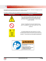
1
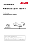
AV Connectivity, Distribution And Beyond... VIDEO WALLS VIDEO PROCESSORS VIDEO MATRIX SWITCHES EXTENDERS SPLITTERS WIRELESS CABLES & ACCESSORIES HDMI LAN Extender up to 100M over Single CAT5/6 Model #: HDM-C6IP-SET © 2013 Avenview Inc. All rights reserved. The contents of this document are provided in connection with Avenview Inc. (“Avenview”) products. Avenview makes no representations or warranties with respect to the accuracy or completeness of the contents of this publication and reserves the right to make changes to specifications and product descriptions at any time without notice. No license, whether express, implied, or otherwise, to any intellectual property rights is granted by this publication. Except as set forth in Avenview Standard Terms and Conditions of Sale, Avenview assumes no liability whatsoever, and disclaims any express or implied warranty, relating to its products of Avenview Inc. is strictly prohibited. Product Application & Market Sectors Corporate House Of Worship Military Residential Education Industrial Medical Aviation www.avenview.com TABLE OF CONTENTS 1. GETTING STARTED...........................................................................................................................1 1.1 Important Safeguards...............................................................................................................1 1.2 Safety Instructions...................................................................................................................1 1.3 Regulatory Notices Federal Communications Commission (FCC)............................ 2 2.INTRODUCTION...............................................................................................................................3 2.1PACKAGE CONTENTS......................................................................................................................4 2.2 BEFORE INSTALLATION....................................................................................................................4 2.3 Device Description & Layout...................................................................................................7 2.3.1 Front Panel & Rear Panel (Transmitter, HDM-C6IP-S)................................................................7 2.3.2 Front Panel & Rear Panel (Receiver, HDM-C6IP-R)....................................................................7 3.INSTALLATION...................................................................................................................................8 4. General Troubleshooting......................................................................................................8 5.SPECIFICATIONS................................................................................................................................9 6.PIN & Wiring Standard Definition.......................................................................................10 www.avenview.com Page 3 1. GETTING STARTED SECTION 1: GETTING STARTED 1.1 Important Safeguards Please read all of these instructions carefully before you use the device. Save this manual for future reference. What the warranty does not cover •• Any product, on which the serial number has been defaced, modified or removed. •• Damage, deterioration or malfunction resulting from: •• Accident, misuse, neglect, fire, water, lightning, or other acts of nature, unauthorized product modification, or failure to follow instructions supplied with the product. •• Repair or attempted repair by anyone not authorized by us. •• Any damage of the product due to shipment. •• Removal or installation of the product. •• Causes external to the product, such as electric power fluctuation or failure. •• Use of supplies or parts not meeting our specifications. •• Normal wear and tear. •• Any other causes which does not relate to a product defect. •• Removal, installation, and set-up service charges. 1.2 Safety Instructions The Avenview HDM-C6IP-SET, HDMI Extender has been tested for conformity to safety regulations and requirements, and has been certified for international use. However, like all electronic equipment’s, the HDM-C6IP-SET should be used with care. Read the following safety instructions to protect yourself from possible injury and to minimize the risk of damage to the unit. ! Do not dismantle the housing or modify the module. ! Dismantling the housing or modifying the module may result in electrical shock or burn. ! Refer all servicing to qualified service personnel. ! Do not attempt to service this product yourself as opening or removing housing may expose you to dangerous voltage or other hazards ! Keep the module away from liquids. ! Spillage into the housing may result in fire, electrical shock, or equipment damage. If an object or liquid falls or spills on to the housing, unplug the module immediately. ! Have the module checked by a qualified service engineer before using it again. ! Do not use liquid or aerosol cleaners to clean this unit. Always unplug the power to the device before cleaning. www.avenview.com Page 1 1.3 Regulatory Notices Federal Communications Commission (FCC) This equipment has been tested and found to comply with Part 15 of the FCC rules. These limits are designed to provide reasonable protection against harmful interference in a residential installation. Any changes or modifications made to this equipment may void the user’s authority to operate this equipment. Warning symbols Description ONLY USE THE PROVIDED POWER CABLE OR POWER ADAPTER SUPPLIED. DO NOT TAMPER WITH THE ELECTRICAL PARTS. THIS MAY RESULT IN ELECTRICAL SHOCK OR BURN. DO NOT TAMPER WITH THE UNIT. DOING SO WILL VOID THE WARRANTY AND CONTINUED USE OF THE PRODUCT. THE VIDEO BOARDS ARE VERY SENSITIVE TO STATIC. PLEASE ENSURE IF RACK MOUNTED OR INSTALLED ON A SURFACE, IT SHOULD BE IN A GROUNDED ENVIROMENT. www.avenview.com Page 2 2.INTRODUCTION HDM-C6IP-SET, HDMI extender set is designed to extend your HD display with the resolutions of 1080p/60Hz up to 330 feet (100 meters) away from your HDMI or DVI-D source. Thanks to the use of the TCP/IP protocol, you can transfer your highdefinition video over an existing TCP/IP network. See below three examples: A: The Tx and Rx units can extend 100 meters over a single CAT5/6 cable connection point to point. B: The Tx can be connected to a Gigabit switch to establish a IP address therefore sending 1080p video signals to Rx connected to the Gigabit switch and the HDMI displays. multiple C: Multiple Tx’s can be connected to a Managed Gigabit switch with VLAN/IGMP support therefore sending 1080p video signals to Rx connected to the Gigabit switch to show different sources on the HDMI displays. •• Extends HDMI up to 95m/100m over single CAT5E/6 •• Supports HDMI, EDID, Support HDCP •• Supports resolution HDTV / 1080Pp/60Hz, Vesa (1920 x 1080) •• Supporting the point to point transmission function currently which can be expanded to the multi-point to point transmission function. •• Requires a managed Gigabit switch with VLAN/IGMP support to have a soultion with multiple sources (Transmitters). Standard Gigabit switch can only support one transmitter. •• The managed switch must support port based IEEE 802.1Q VLAN, IGMP, and to allow duplicate IP addresses across the VLAN domains. •• Each VLAN acts as independent HDMI over IP Channel on the network. •• Number of Tx and Rx that can be used is dependent on bandwidth of the switch (Recommended Gigabit switch 10/1000). •• Managed switches can be cascaded up to 3 levels, allowing the farthest display to be located up to 300 meters away from the source device. Each receiver can be located up to 100 meters away. •• Uses M-JPEG technology to process image compression on a fixed bandwidth. www.avenview.com Page 3 2.1PACKAGE CONTENTS Before you start the installation of HDM-C6IP-SET, please check the A. STANDARD package contents. 1 HDMI Transmitter x1 2 HDMI Receiver x1 3 Power Adapter (5VDC) x2 4 User’s ManualX1 2.2 BEFORE INSTALLATION •• Put the product in an even and stable location. If the product falls down or drops, it may cause an injury or malfunction. •• Don’t place the product in too high temperature (over 50°C), too low temperature (under 0°C) or high humidity. •• Use the DC power adapter with correct specifications. If inappropriate power supply is used then it may cause a fire. www.avenview.com Page 4 www.avenview.com Page 5 www.avenview.com Page 6 2.3 Device Description & Layout This product is composed of a Transmitter and a Receiver. 2.3.1 Front Panel & Rear Panel (Transmitter, HDM-C6IP-S) 1 2 3 4 1 CAT5E/6: Plug in a Cat-5E/6 cable that needs to be linked to the receiving unit 3 +5V DC: Connect to 5V DC power supply. 2 SELECT: To pair with the corresponding Transmitter unit. 4 HDMI IN: Connects to a HDMI source with a HDMI male-male cable. 2.3.2 Front Panel & Rear Panel (Receiver, HDM-C6IP-R) 1 2 3 4 1 CAT5E/6: Plug in a Cat-5E/6 cable that needs to be linked to the receiving unit 3 +5V DC: Connect to 5V DC power supply. 2 SELECT: To pair with the corresponding Transmitter unit. 4 HDMI OUT: Connects to a HDMI source with a HDMI male-male cable. •• Each Transmitter and Receiver after pairing support only point to point operation. It cannot support signals broadcasting by HDMI. •• Important Before starting the insulation please ensure that all devices are powered OFF www.avenview.com Page 7 3.INSTALLATION Please ensure all the package contents are all received. To setup Avenview HDM-C6IP-SET follow these steps for connecting to a device: 1. Connect your HDMI source (such as a Blu-ray Disc player) to Transmitter (HDM-C6IP-S). 2. Connect your HDMI display (such as a LCD TV) to the receiving unit HDM-C6IP-R. 3. Connect your CAT-5E/6 follow the standards of TIA-568BLAN cable between the transmitting and receiving units. 4. Make sure CAT-5E/6 LAN cable is tightly connected and not loose. 5. Plug in 5V DC power cord to the power jack of the transmitting unit HDM-C6IP-S 6. Plug in 5V DC power cord to the power jack of the receiving unit HDM-C6IP-R. 4. General Troubleshooting PROBLEM NO IMAGE SCREEN DEFECTS APPEAR POSSIBLE SOLUTION • Check if connection to the source and the display are correct. • Ensure that display device supports 480p, 720p and 1080p resolution • Check the DVI and HDMI connection Yellow Light on LAN port flashing SLOW • Check both units and make sure the TX and RX are not Reversed Yellow Light on LAN Port flashing Fast/NO Image • Check Graphics card on PC. This product supports up to 1080p (1920x1080) resolution. No Yellow Light on LAN port • Check Network cable only use TIA-568B Standard • Check the source device is powered ON • Network cable run is out of range www.avenview.com Page 8 5.SPECIFICATIONS ITEM DESCRIPTION Units HDM-C6IP-S Unit Description HDM-C6IP-R HDMI Transmitter HDMI Receiver HDMI Compliance Full HD HDCP Compliance Yes Video Bandwidth M-JPEG technology to process image compressing GIGABIT (10/1000) OVER LAN Supported Resolutions 480i@60Hz, 480p@60Hz, 576i@50Hz, 576p@50Hz, 720p@50/60Hz, 1080i@50/60Hz, 1080p@50/60Hz Resolution and Distance (24-bit) Full HD: (1080p)-95meter (295feet) (CAT5e) / 100meter (328feet) (CAT6) Audio Support Surround Sound (up to 7.1 Ch) or Stereo Digital Audio IR Pass-thru NO RS-232 Support NO Input Output 1x HDMI 1x RJ45 1x RJ45 1x HDMI + 1x 3.5mm HDMI Connector Type A (19 pin female) RJ45 Connector WE/SS 8P8C with 2 LED indicators Power Adapter 2 X DC 5V/1A Power Consumption 3W Max Each Dimension L x W x H (Tx: 4.3” Rx: 4.3”) x (Tx: 2.2” Rx: 2.2”) x (Tx: 1” Rx: 1”) Weight 245g Environmental Operating Temperature 32˚ ~ 104˚F (0˚ to 40˚C) Storage Temperature -4˚ ~ 140˚F (-20˚ ~ 60˚C) Relative Humidity 20~90% RH (no condensation) PERFORMANCE GUIDE FOR HDMI OVER CATEGORY CABLE TRANSMISSION PERFORMANCE RATING SHIELDING WIRING SOLID STRANDED TYPE OF CATEGORY CABLE CAT5 CAT5E CAT6 UNSHIELDED (UTP) SHIELDED (STP) UNSHIELDED (UTP) SHIELDED (STP) TERMINATION PLEASE USE EIA/TIA-568-B TERMINATION (T568B) AT ANY TIME www.avenview.com Page 9 6.PIN & Wiring Standard Definition Type A (Receptacle) HDMI Pin 1 TMDS Data2+ Pin 11 TMDS Clock Shield Pin 2 TMDS Data2 Shield Pin 12 TMDS Clock– Pin 3 TMDS Data2– Pin 13 CEC Pin 4 TMDS Data1+ Pin 14 Reserved (N.C. on device) Pin 5 TMDS Data1 Shield Pin 15 SCL Pin 6 TMDS Data1– Pin 16 SDA Pin 7 TMDS Data0+ Pin 17 DDC/CEC Ground Pin 8 TMDS Data0 Shield Pin 18 +5V Power Pin 9 TMDS Data0– Pin 19 Hot Plug Detect Pin 10 TMDS Clock+ www.avenview.com Page 10 Notes www.avenview.com Page 11 Avenview Warranty Certificate AVENVIEW CORP. (“Avenview”) warrants Avenview-branded product(s) contained in the original packaging against defects in materials and workmanship when used normally in accordance with Avenview's enclosed manual guidelines for a period of THREE (3) YEARS from the date of original retail purchase - Warranty Period. Avenview’s published guidelines include but are not limited to information contained in technical specifications, user manuals and service communications. LABOR: During the Warranty Period of THREE (3) YEARS, Avenview will repair or replace the product(s) at no cost using new or used parts equivalent to novel performance and reliability if the product(s) is determined to have abide by Avenview’s published guidelines. Cost of Labor applicable to product(s) after Warranty Period. For labor costs, please contact [email protected]. PARTS: During the Warranty Period of of THREE (3) YEARS, Avenview will supply new or rebuilt replacements in exchange for defective parts of the product(s) at no cost if the product(s) is determined to have abide by Avenview’s published guidelines. Cost of Parts applicable to product(s) after Warranty Period. For part(s) costs, please contact [email protected]. To obtain Warranty: (a) proof of purchase in the form of a bill of sale or receipted invoice reflecting that the registered product(s) is within warranty period must be presented to obtain warranty service; (b) product(s) must be registered at time of purchase. Failure to do so will result in applicable parts and labor charges. Returning product(s) must be shipped in Avenview’s original packaging or in packaging pertaining equal degree of protection to Avenview’s. Both Avenview and purchaser are responsible for freight charges and brokerages when shipping the product(s) to the receiver. NOT COVERED BY THIS WARRANTY This warranty does not apply to any non-Avenview branded product(s); non-registered Avenview product(s). This warranty does not apply: (a) to cosmetic damage, including but not limited to scratches, dents and broken cords; (b) to damage caused by use with another product; (c) to damage caused by accident, abuse, misuse, liquid contact, fire, earthquake or other external cause; (d) to damage caused by operating the Avenview product(s) outside Avenview’s manuals or guidelines; (e) to damage caused by service performed by anyone who is not a representative of Avenview or an Avenview authorized personnel; (f) to defects caused by normal wear and tear or otherwise due to the normal aging of the Avenview product(s), or (g) if any serial number has been removed or defaced from the Avenview product(s). AVENVIEW IS NOT LIABLE FOR DIRECT, SPECIAL, INCIDENTAL OR CONSEQUENTIAL DAMAGES RESULTING FROM ANY BREACH OF WARRANTY OR CONDITION, OR UNDER ANY OTHER LEGAL THEORY, INCLUDING BUT NOT LIMITED TO LOSS OF USE; LOSS OF REVENUE; LOSS OF ACTUAL OR ANTICIPATED PROFITS (INCLUDING LOSS OF PROFITS ON CONTRACTS); LOSS OF THE USE OF MONEY; LOSS OF ANTICIPATED SAVINGS; LOSS OF BUSINESS; LOSS OF OPPORTUNITY; LOSS OF GOODWILL; LOSS OF REPUTATION; LOSS OF, DAMAGE TO, COMPROMISE OR CORRUPTION OF DATA; OR ANY INDIRECT OR CONSEQUENTIAL LOSS OR DAMAGE REPAIR OR REPLACEMENT AS PROVIDED UNDER THIS WARRANTY IS THE EXCLUSIVE REMEDY OF THE CONSUMER. Some states do not allow the inclusion or limitation of incidental or consequential damages, or allow limitations on duration implements of the Warranty Period; therefore the above limitations or exclusions may not be applicable to you. This warranty gives you specific legal rights, and you may have other rights which vary from state to state. 275 Woodward Avenue, Kenmore, NY 14217 1.866.508.0269 www.avenview.com Page 12 AV Connectivity, Distribution And Beyond... TECHNICAL SUPPORT Disclaimer While every precaution has been taken in the preparation of this document, Avenview Inc. assumes no liability with respect to the operation or use of Avenview hardware, software or other products and documentation described herein, for any act or omission of Avenview concerning such products or this documentation, for any interruption of service, loss or interruption of business, loss of anticipatory profits, or for punitive, incidental or consequential damages in connection with the furnishing, performance, or use of the Avenview hardware, software, or other products and documentation provided herein. Avenview Inc. reserves the right to make changes without further notice to a product or system described herein to improve reliability, function or design. With respect to Avenview products which this document relates, Avenview disclaims all express or implied warranties regarding such products, including but not limited to, the implied warranties of merchantability, fitness for a particular purpose, and non-infringement.