1
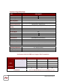
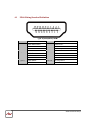
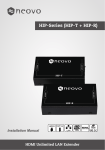
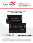
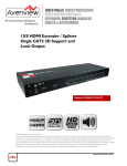
HDMI LAN Extender up to 100M over Single CAT5/6 Model #: HDM3D-C53X-SET © 2012 Avenview Inc. All rights reserved. The contents of this document are provided in connection with Avenview Inc. (“Avenview”) products. Avenview makes no representations or warranties with respect to the accuracy or completeness of the contents of this publication and reserves the right to make changes to specifications and product descriptions at any time without notice. No license, whether express, implied, or otherwise, to any intellectual property rights is granted by this publication. Except as set forth in Avenview Standard Terms and Conditions of Sale, Avenview assumes no liability whatsoever, and disclaims any express or implied warranty, relating to its products including, but not limited to, the implied warranty of merchantability, fitness for a particular purpose, or infringement of any intellectual property right. Reproduction of this manual, or parts thereof, in any form, without the express written permission of Avenview Inc. is strictly prohibited. Table of Contents Section 1: Getting Started ...................................................................................................................... 3 1.1 Important Safeguards ............................................................................................................ 3 1.2 Safety Instructions ................................................................................................................. 3 1.3 Regulatory Notices Federal Communications Commission (FCC) ......................................... 4 1.4 Introduction ........................................................................................................................... 4 1.5 Package Contents................................................................................................................... 4 1.6 Before Installation.................................................................................................................. 4 1.7 Device Description & Layout .................................................................................................. 5 1.8 Installation ............................................................................................................................. 6 Section 3: General Troubleshooting....................................................................................................... 6 Section 4: Specifications......................................................................................................................... 7 4.1 PIN & Wiring Standard Definition .......................................................................................... 8 www.avenview.com|2 Section 1: Getting Started 1.1 Important Safeguards Please read all of these instructions carefully before you use the device. Save this manual for future reference. What the warranty does not cover Any product, on which the serial number has been defaced, modified or removed. Damage, deterioration or malfunction resulting from: Accident, misuse, neglect, fire, water, lightning, or other acts of nature, unauthorized product modification, or failure to follow instructions supplied with the product. Repair or attempted repair by anyone not authorized by us. Any damage of the product due to shipment. Removal or installation of the product. Causes external to the product, such as electric power fluctuation or failure. Use of supplies or parts not meeting our specifications. Normal wear and tear. Any other causes which does not relate to a product defect. Removal, installation, and set-up service charges. 1.2 Safety Instructions The Avenview HDM-C6IP-SET, HDMI Extender has been tested for conformity to safety regulations and requirements, and has been certified for international use. However, like all electronic equipment’s, the HDM-C6IP-SET should be used with care. Read the following safety instructions to protect yourself from possible injury and to minimize the risk of damage to the unit. Do not dismantle the housing or modify the module. Dismantling the housing or modifying the module may result in electrical shock or burn. Refer all servicing to qualified service personnel. Do not attempt to service this product yourself as opening or removing housing may expose you to dangerous voltage or other hazards Keep the module away from liquids. Spillage into the housing may result in fire, electrical shock, or equipment damage. If an object or liquid falls or spills on to the housing, unplug the module immediately. Have the module checked by a qualified service engineer before using it again. Do not use liquid or aerosol cleaners to clean this unit. Always unplug the power to the device before cleaning. www.avenview.com|3 1.3 Regulatory Notices Federal Communications Commission (FCC) This equipment has been tested and found to comply with Part 15 of the FCC rules. These limits are designed to provide reasonable protection against harmful interference in a residential installation. Any changes or modifications made to this equipment may void the user’s authority to operate this equipment. 1.4 Introduction HDM-C6IP-SET, HDMI extender set is designed to extend your HD display with the resolutions of 1080p/60Hz up to 330 feet (100 meters) away from your HDMI or DVI-D source. Thanks to the use of the TCP/IP protocol, you can transfer your high-definition video over an existing TCP/IP network. See below three examples: A :-The Tx and Rx units can extend 100 meters over a single CAT5/6 cable connection point to point. B:- The Tx can be connected to a router to establish a IP address therefore sending 1080p video signals to multiple Rx connected to the router to the desired displays. C:- The Tx can be connected to a router with internet to establish a DHCP address therefore sending 1080p video signals to Rx connected to the router to the desired displays. 1.5 Extends HDMI up to 95m/100m over single CAT5E/6 Supports HDMI, EDID, Support HDCP Supports resolution HDTV / 1080Pp/60Hz, Vesa (1920 x 1080) Supporting the point to point transmission function currently which can be expanded to the multi-point to point transmission function. Package Contents Before you start the installation of HDM-C6IP-SET, please check the A. STANDARD package contents. - 1.6 HDMI Transmitter HDMI Receiver Power Adapter (5VDC) User Manual x1 x1 x2 Before Installation Put the product in an even and stable location. If the product falls down or drops, it may cause an injury or malfunction. Don’t place the product in too high temperature (over 50°C), too low temperature (under 0°C) or high humidity. Use the DC power adapter with correct specifications. If inappropriate power supply is used then it may cause a fire. www.avenview.com|4 1.7 Device Description & Layout This product is composed of a Transmitter and a Receiver. FRONT PANEL & REAR PANEL (Transmitter, HDM-C6IP-S) 1 2 3 4 1. CAT5E/6: Plug in a Cat-5E/6 cable that needs to be linked to the receiving unit 3. +5V DC: Connect to 5V DC power supply. 2. SELECT: To pair with the corresponding Receiver unit. 4. HDMI IN: Connects to a HDMI source with a HDMI male-male cable. FRONT PANEL & REAR PANEL (Receiver, HDM-C6IP-R) 1 2 3 4 1. CAT5E/6: Plug in a Cat-5E/6 cable that needs to be linked to the receiving unit 3. +5V DC: Connect to 5V DC power supply. 2. SELECT: To pair with the corresponding Transmitter unit. 4. HDMI OUT: Connects to a HDMI source with a HDMI male-male cable. www.avenview.com|5 1.8 Each Transmitter and Receiver after pairing support only point to point operation. It cannot support signals broadcasting by HDMI. Important Before starting the insulation please ensure that all devices are powered OFF Installation Please ensure all the package contents are all received. To setup Avenview HDM-C6IP-SET follow these steps for connecting to a device: 1. Connect your HDMI source (such as a Blu-ray Disc player) to Transmitter (HDM-C6IP-S). 2. Connect your HDMI display (such as a LCD TV) to the receiving unit HDM-C6IP-R. 3. Connect your CAT-5E/6 follow the standards of TIA-568BLAN cable between the transmitting and receiving units. 4. Make sure CAT-5E/6 LAN cable is tightly connected and not loose. 5. Plug in 5V DC power cord to the power jack of the transmitting unit HDM-C6IP-S 6. Plug in 5V DC power cord to the power jack of the receiving unit HDM-C6IP-R. Section 3: General Troubleshooting Problem No Image Screen Defects Appear Yellow Light on LAN port flashing SLOW Yellow Light on LAN Port flashing Fast/NO Image No Yellow Light on LAN port Possible Solution Check if connection to the source and the display are correct. Ensure that display device supports 480p, 720p and 1080p resolution Check the DVI and HDMI connection Check both units and make sure the TX and RX are not Reversed Check the source device is powered ON Check Graphics card on PC. This product supports up to 1080p (1920x1080) resolution. Check Network cable only use TIA-568B Standard Network cable run is out of range www.avenview.com|6 Section 4: Specifications Item Units Unit Description HDMI Compliance Description HDM3D-C6IP-S HDMI 1.3a Transmitter HDM3D-C6IP-R HDMI 1.3a Receiver Full HD HDCP Compliance Video Bandwidth Yes M-JPEG technology to process image compressing GIGABIT (10/1000) OVER LAN Supported Resolutions Resolution and Distance (24-bit) Audio Support IR Pass-thru RS-232 Support Input Output HDMI Connector RJ45 Connector Power Adapter Power Consumption Dimension L x W x H Weight 480i@60Hz, 480p@60Hz, 576i@50Hz, 576p@50Hz, 720p@50/60Hz, 1080i@50/60Hz, 1080p@50/60Hz Full HD: (1080p)-95meter (295feet) (CAT5e) / 100meter (328feet) (CAT6) Surround Sound (up to 7.1 Ch) or Stereo Digital Audio NO NO 1x HDMI 1x RJ45 1x RJ45 1x HDMI + 1x 3.5mm Type A (19 pin female) WE/SS 8P8C with 2 LED indicators 2 X DC 5V/1A 3W Max Each 110 x 58 x 26mm (4.3” x 2.2” x 1”) 245g Environmental Operating Temperature Storage Temperature Relative Humidity 32˚ ~ 104˚F (0˚ to 40˚C) -4˚ ~ 140˚F (-20˚ ~ 60˚C) 20~90% RH (no condensation) Performance Guide for HDMI over Category Cable Transmission Performance rating Wiring Solid Stranded Shielding Type of category cable CAT5 CAT5e CAT6 Unshielded (UTP) Shielded (STP) Unshielded (UTP) Shielded (STP) Termination Please use EIA/TIA-568-B termination (T568B) at any time www.avenview.com|7 4.1 PIN & Wiring Standard Definition Type A (Receptacle) HDMI Pin 1 TMDS Data2+ Pin 11 TMDS Clock Shield Pin 2 TMDS Data2 Shield Pin 12 TMDS Clock– Pin 3 TMDS Data2– Pin 13 CEC Pin 4 TMDS Data1+ Pin 14 Reserved (N.C. on device) Pin 5 TMDS Data1 Shield Pin 15 SCL Pin 6 TMDS Data1– Pin 16 SDA Pin 7 TMDS Data0+ Pin 17 DDC/CEC Ground Pin 8 TMDS Data0 Shield Pin 18 +5V Power Pin 9 TMDS Data0– Pin 19 Hot Plug Detect Pin 10 TMDS Clock+ www.avenview.com|8 Disclaimer While every precaution has been taken in the preparation of this document, Avenview Inc. assumes no liability with respect to the operation or use of Avenview hardware, software or other products and documentation described herein, for any act or omission of Avenview concerning such products or this documentation, for any interruption of service, loss or interruption of business, loss of anticipatory profits, or for punitive, incidental or consequential damages in connection with the furnishing, performance, or use of the Avenview hardware, software, or other products and documentation provided herein. Avenview Inc. reserves the right to make changes without further notice to a product or system described herein to improve reliability, function or design. With respect to Avenview products which this document relates, Avenview disclaims all express or implied warranties regarding such products, including but not limited to, the implied warranties of merchantability, fitness for a particular purpose, and non-infringement. www.avenview.com|9