1
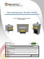
The Mahogany Wood Stove
INSTALLATION & OPERATIONAL INSTRUCTIONS OWNER’S MANUAL MANUFACTURED BY: Breckwell Hearth Products Arlington, TX & Eugene, OR PROFESSIONAL INSTALLATION IS HIGHLY RECOMENDED
WARNING: If your appliance is not properly installed a house fire may result. For your safety, follow
the installation directions. Contact local building or fire officials about restrictions and installation inspection requirements in
your area. Local regulations and requirements can supersede those specified in this manual if more
stringent. PLEASE read this entire manual before installation and use of this wood burning room heater.
Failure to follow these instructions could result in property damage, bodily injury, or even death. Save these instructions. ©Breckwell Hearth Products – 2010 All Rights Reserved www.breckwell.com TABLE OF CONTENTS
Introduction ............................................................................................................................................................... 2 Safety Precautions ................................................................................................................................................... 3 Safety Information ................................................................................................................................................... 4 Chimney Cleaning & Inspection ............................................................................................................................. 4 Installation ................................................................................................................................................................. 5 Stove Specifications and Performance .................................................................................................................. 5 Clearances ............................................................................................................................................................. 5 Venting ...................................................................................................................................................................... 7 Natural Draft .......................................................................................................................................................... 7 Negative Pressure .................................................................................................................................................. 7 Installation ................................................................................................................................................................. 8 Pedestal Assembly – Freestanding Model ............................................................................................................. 9 Leg Assembly – Freestanding Model ..................................................................................................................... 9 Optional Blower Installation ................................................................................................................................ 10 Outside Air Kit – FS Pedestal Units ...................................................................................................................... 11 Outside Air Kit – FS Leg Units .............................................................................................................................. 12 Flashing Installation – Insert Models ................................................................................................................... 13 Mobile or Manufactured Home Requirements ................................................................................................... 13 Installing the Brick Panels .................................................................................................................................... 14 Freestanding Installation Requirements ............................................................................................................. 15 Insert Installation Requirements ......................................................................................................................... 18 Block‐Off Plate Installation .............................................................................................................................. 19 Operating Your Wood Stove .................................................................................................................................... 22 Building a Fire ...................................................................................................................................................... 22 Disposal of Ashes ................................................................................................................................................. 22 Keeping The Door Glass Clean ............................................................................................................................. 22 Maximizing Your Stoves Efficiency ...................................................................................................................... 23 Achieving Long, Clean Burns ................................................................................................................................ 23 Stove Maintenance .................................................................................................................................................. 24 Troubleshooting ...................................................................................................................................................... 24 Proper Fuel & Storage ............................................................................................................................................. 25 Door Assembly & Glass Replacement ..................................................................................................................... 26 Replacement Parts .................................................................................................................................................. 27 America’s Favorite Stoves Since 1980 Page 1 INTRODUCTION
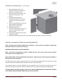
Thank you for purchasing the Breckwell Mahogany Wood Burning Stove. To achieve the safest, highest efficiency, and most enjoyable performance from your stove, you must do three things: 1) Install it properly. 2) Operate it correctly. 3) Maintain it regularly. The purpose of this manual is to help you do all three. CAUTION: DO NOT USE MAKE‐SHIFT MATERIALS OR COMPROMISES DURING INSTALLATION. SERIOUS PROPERTY DAMAGE AND BODILY INJURY OR EVEN DEATH MAY RESULT. PLEASE read this entire manual thoroughly before you install and operate your new room heater and KEEP THIS MANUAL in a handy place for future reference. Failure to follow instructions may result in property damage, bodily injury, or even death. This stove has been independently tested and approved in accordance with the relevant portions of UL 1482‐2010 “Solid‐Fuel Type Room Heaters”, and ULC S627‐00 and ULC S628‐93. Consult with your local building code agency or fire officials, and insurance representative before you begin your installation to ensure compliance with installation inspection, local codes, including the need for permits and follow‐up inspections. The W3100FS and W3100I must be installed in accordance with the manufacture’s installations and with local codes. Burn your stove moderately hot during the first couple of fires to allow the paint to cure. Do not set anything on top of the stove and clear any dust or debris off of the stove before firing. The paint will become soft and gummy as the stove heats up and will harden as the stove cools. During the break‐in period, open the door frequently (every 5 – 10 minutes) to keep the door gasket from sticking to the paint as it cures. During the paint curing process, it will emit a non‐toxic smoke. Opening a window near the stove will help this to dissipate. Only High Temp Paint, available from your Breckwell dealer, should be used for touch‐ups. We recommend Stove Bright #6309 – Metallic Black. During the first few weeks, the stove will go through a process if eliminating moisture in the steel and firebrick. This moisture will reduce the initial heat output of the stove. Once the paint has cured, it will be necessary to build several hot fires to remove this moisture. For the first week or two, burn the stove with the damper wide open for an hour and use generous amounts of fuel. DO NOT OVERFIRE THE STOVE DURING THIS PROCESS. IF THE STOVE OR CHIMNEY BECOMES RED, REDUCE THE AMOUNT OF AIR COMING INTO THE STOVE. Commercial and industrial installations of Breckwell Wood Stoves should not be used since operational control is often not well managed in these settings. Model: W3100 Wood Stove Style: Freestanding or Insert Serial Number: Purchase Date: Purchased From: America’s Favorite Stoves Since 1980 MAIL YOUR WARRANTY CARD TODAY To receive full warranty coverage, you will need to show evidence of the date you purchased your stove. We suggest that you attach your sales invoice to this page, and fill in the form on the left, so that you will have all the information you need in one place should the need for service or information occur. Page 2 SAFETY PRECAUTIONS
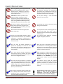
Never use gasoline, gasoline type lantern fuel, kerosene, charcoal lighter fluid, or similar liquids to start or “freshen up” a fire in this stove. Keep all such liquids well away from the stove while in use. CAUTION: Hot while in operation. Keep children, clothing, and furniture away. Contact may cause skin burns. Educate all children of the danger of a high temperature stove. Young children should be supervised when they are in the same room as the stove. The viewing door must be closed and latched during normal operation. If at any time the stove or chimney glows red, you are over firing your stove! This is dangerous and may result in property damage or bodily injury. Never block free airflow through the open vents of the stove. Do not place clothing or other flammable items on or near the stove. Do not try to repair or replace any part of the stove unless instructions are given in this manual. All other work should be performed by a trained technician. Do not throw this manual away. This manual has important operating and maintenance instructions that you will need at a later time. Always follow the instructions in this manual and please read the manual thoroughly. Contact your local building officials to obtain a permit and information on any installation restrictions or inspection requirements in your area. Notify your insurance company of this stove as well. The exhaust system must be completely airtight and properly installed. This unit must be properly installed to prevent the possibility of a house fire. The instructions must be strictly adhered to. Do not use makeshift methods or compromise in the installation. Your stove requires periodic maintenance and cleaning. Failure to maintain your stove may lead to smoke spillage in your home, or even a more dangerous situation. When installed in a mobile home, the stove must be bolted to the floor, have outside air connected (see page 10), and NOT BE INSTALLED IN A BEDROOM (Per H.U.D. requirements). Check with local building officials. Allow the stove to cool before carrying out any maintenance or cleaning. Ashes must be disposed in a metal container with a tight lid and placed on a non‐combustible surface well away from the home structure. This stove must be connected to a standard 120 V., 60 Hz grounded electrical outlet when using the optional blower kit. Do not use an adapter plug or sever the grounding plug. Do not route the electrical cord underneath, in front of, or over the stove. The exhaust system should be checked regularly. It is recommended that the exhaust system be inspected, as a minimum, at least twice a year for any accumulation of soot or creosote. Use only dry seasoned wood no longer than 18”. The dryer the wood the better for clean and efficient burns. Combustion chamber is 16” front to back and 18” side to side. America’s Favorite Stoves Since 1980 Breckwell Hearth Products grants no warranty, implied or stated, for the installation or maintenance of your stove, and assumes no responsibility of any consequential damage(s). Page 3 SAFETY INFORMATION
When operating your W3100FS and W3100I, respect basic safety standards. Read these instructions carefully and completely before beginning any installation procedures or attempting to operate the heater. Failure to do so may result in damage to property or personal injury and may void the product warranty. CAUTION: DO NOT BURN GARBAGE OR FLAMMABLE FLUIDS SUCH AS GASOLINE, NAPTHA OR ENGINE OIL. CAUTION: WHILE THE STOVE IS BURNING, THE DAMPER ROD MUST BE FULLY OPEN BEFORE OPENING THE DOOR TO AVOID COMBUSTION FLASH. Installation and repair of the W3100FS and W3100I Wood Stove should be done by a qualified service person. The W3100FS and W3100I, Chimney connector and chimney should be inspected by a qualified service person before the heating season, and at least once a month during the heating season to determine if a creosote build‐up had occurred. CAUTION: DO NOT CONNECT TO ANY AIR DISTRIBUTION DUCT OR SYSTEM. Due to high surface temperatures, the W3100FS and W3100I should be located out of traffic areas and away from furniture and draperies. Children and adults should be alerted to the hazards of high surface temperatures and should stay away to avoid burns or clothing ignition. Young children should be carefully supervised when they are in the same room as the heater. If the blower cover plate (W3100FS) or the optional blower assembly have been removed for service, they must be replaced prior to operating the heater. WARNING: DO NOT OPERATE HEATER WITH THE GLASS PANEL REMOVED, CRACKED OR BROKEN. REPLACEMENT OF THE PANEL SHOULD BE DONE BY A LICENSED OR QUALIFIED SERVICE PERSON. Ensure adequate combustion and ventilation air are provided, and that they are not obstructed. CREOSOTE – FORMATION AND NEED FOR REMOVAL When wood is burned slowly, it produces tar and other organic vapors, which combine with expelled moisture to form creosote. The creosote vapors condense in the relatively cool chimney flue of a slow‐
burning fire. As a result, creosote residue accumulates on the flue lining. When ignited, this creosote makes an extremely hot fire, which may damage the chimney or even cause a house fire. In the event of a chimney fire, CALL THE FIRE DEPARTMENT IMMEDIATELY. Chimney Cleaning & Inspection
Before each heating season the entire chimney system, combustion chamber, and fireplace should be professionally inspected, cleaned and, if necessary, repaired. The chimney connector and chimney should be inspected at least once a month during the heating season to determine if creosote build‐up has occurred. The chimney system should be inspected at the chimney connector and at the chimney top. Cooler surfaces tend to build creosote deposits quicker, so it is important to check the chimney from the top as well as from the bottom. If creosote has accumulated it should be removed to reduce the risk of a chimney fire. The creosote should be removed with a brush specifically designed for the type of chimney in use. A qualified chimney sweep can perform this service. NOTE: For insert installations it will be necessary to remove the insert for proper inspection and cleaning. America’s Favorite Stoves Since 1980 Page 4 Chapter 1 Specifications & Clearances INSTALLATION
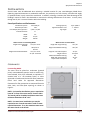
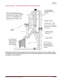
Several issues must be addressed when selecting a suitable location for your new Mahogany Wood Stove. Observing required clearances to combustible materials, the proximity to a safe chimney, and electrical supply (if optional blower in use) must all be considered. In addition, selecting a location that takes advantage of the building’s natural air flow is also desirable to maximize the heating effectiveness of the stove. In many cases, though not all, this is a central location within the building. Stove Specifications and Performance Combustion System: Non‐Catalytic
EPA Grams per Hour: 2.28
Heat Output (BTU’s/per hour: 9,500 – 37,000
Exhaust Diameter: 6” Width: 25”
Depth: 22‐1/2”
Weight: 430 lbs.
When used as a Freestanding Model Height with Log Storage 37‐1/8” to Front
Pedestal: 38‐13/16” to Shroud Height with Standard Pedestal: 31‐1/4” to Front
32‐7/8” To Shroud
Heating Capacity: Up to 1,800 sf
Approximate Burn Time: 7 – 9 Hours
Log Length: 18”
When used as an Insert Model
Height with Large Flashing: 32‐1/16”
Height with Medium Flashing: 30‐1/16”
Height of unit inside fireplace: Height of Stove: Width with Medium Flashing: Width with Large Flashing: Depth Inside of Fireplace: 20‐1/2”
18‐13/16”
42”
48‐1/2”
15”
Clearances
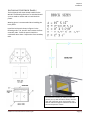
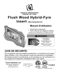
Freestanding Model The stove must be placed on continuous (grouted joints) noncombustible material such as ceramic tile, cement board, brick, 3/8” millboard or equivalent ¼” material with a k+ .84 insulation factor, or other approved or listed material suited for floor protection. Check local codes for approved alternatives. Clearances for floor protection are measured from the sides, back, and face (door opening) as shown in Figure 1. NOTE: For Canadian installations you are required to have 18” in front of the stove and 8” from the sides. The hearth pad for Canadian installations must have minimum dimensions of 46” x 41”. NOTE: For some insert installations you may be required to use a hearth extension in order to meet required clearances. If so, the extensions must meet the same criteria as the hearth. America’s Favorite Stoves Since 1980 Figure 1 Page 5 Chapter 1 Specifications & Clearances Minimum clearance to combustible must be maintained as shown in figure 2 and the following chart. A B* C D* E* F G H Single Wall Connector 24” 14” 16” 14” 7” 16” 84” 30” Double Wall Connector 22” 12‐1/2”
12” 10” 7” 16” 84” 30” Alcove with Double Wall 22” 12‐1/2”
12” 10” 7” 16” 84” 30” Mobile Home Double Wall 22” 12‐1/2”
12” 10” 7” 16” 84” 30” * Provided for reference only. Always maintain the clearances listed to the pipe. ALCOVE INSTALLATION: Heat Shield is REQUIRED with a minimum of 2’ Diameter & 1” from Ceiling. Double Wall Pipe is REQUIRED.
Insert Model Minimum Clearances to combustibles must be maintained as shown in the following chart. NOTE: Materials projecting more than ¾” from the wall are considered mantels. I J K L M N O P Q W3100I 17” 32” 32” 15” 20‐1/2” 4‐9/16” 5‐5/8” 15” 8” W3100I w/Heat Shield* 16” 24” 18” 15” 20‐1/2” 4‐9/16” 5‐5/8” 15” 8” *Use on the Breckwell Heat Shield – Part Number CW‐S‐157 Combustible Trim All Insert Installations require a minimum of 1” of k=0.84 material for the hearth. America’s Favorite Stoves Since 1980 Only Zero Clearance Installations Require
the Bottom 2” Clearance Page 6 Chapter 2 Venting Requirements VENTING
Proper venting of your stove is very important for good clean burns with high efficiency. In addition, venting can have a direct impact upon the safety of your stove. The Mahogany Wood Stove is approved for use with double wall connector and the same manufacturers’ chimney system as follows: Simspon Dura‐Vent Model DVL Selkirk Metalbestos DS Security Chimneys Model DL 1. Chimney must comply with the requirements for Type HT chimneys in the standard for Chimneys’ Factory‐Built, Residential Type and Building Heating Appliance, UL 103, or a code‐approved masonry chimney with flue liner. 2. Install the chimney in accordance with all of the instructions provided by the chimney manufacturer. NOTE: Your chimney must comply with local building and fire codes. Check with your local officials for additional requirements. 3. Install the first piece of pipe, crimped end down, into the flue collar on the stove ensuring an airtight connection. Secure with screws through side of flue collar. Continue stacking pipe in this manner until within reach of chimney. Use only an air tight slip joint to make the connection to the chimney. All horizontal runs of pipe should be as short as CAN/CSA‐B365 also gives some approved method for possible and are required by NFPA No. 211 to have an passing a flue pipe through combustible constructions. upward pitch or rise in the same direction the smoke Natural Draft
travels of no less than ¼” to the linear foot. The connector pipe must meet minimum clearances in any The chimney serves a dual purpose of drawing combustion air into the stove and exhausting direction to walls or other combustible materials. It combustion by‐products. Draft is the force which must attach to a listed metal chimney at least 6” in moves exhaust gases up the chimney (hot air rises). As diameter with a minimum thickness of 24 gauge, or to the exhaust rises up the chimney, combustion air is a masonry chimney with a flue passage of at least 48 drawn into the stove to replace it. Your stove relies on square inches. natural draft for its only source of combustion air. Poor draft can cause poor combustion and smoke. Too It is required that a chimney connector pipe not much draft can cause excessive burn rates and high extend further than the inner wall of the flue when it temperature in the stove. Some of the things that can is connected to a masonry chimney, and that it either affect natural drafting are size and length of the be cemented to the masonry or be installed without chimney, nearby obstructions, and geographical cement in a thimble connected to the masonry wall. location. Your Breckwell dealer will be able to help When the connector is inserted in a thimble, the joint must be tight enough so that it will not be dislodged in you match your stove to a proper chimney system. normal use. Install the connector at no less than the minimum clearances from the ceiling when using a 90‐ Negative Pressure
This stove is not to be operated in a negative pressure degree elbow to pass through combustible area. Negative pressure can be caused by large constructions. exhaust fans in airtight homes, or by air return for a Chimney connector pipes should never pass through a forced air heating systems in the same room as the stove. This can lead to back drafting of the stove floor, ceiling, firewall, and partition or combustion pulling combustion exhaust into the room. An outside construction of any type unless certain precautions air source connected to the stove will not eliminate are taken. The best method is to use a listed thimble the source of negative pressure. To eliminate negative and a listed insulated chimney in accordance with the pressure problems, be sure your home has an manufacturer’s directions. NFPA No. 211 and adequate make‐up air supply.
America’s Favorite Stoves Since 1980 Page 7 Chapter 3 Installation INSTALLATION
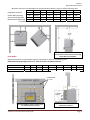
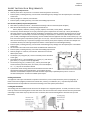
It is extremely important that you properly install your new wood stove in accordance with all manufacturer’s requirements, chimney manufacturer’s requirements, and local regulation. Failure to properly install your stove can result in reduced efficiency of your new appliance, and may even result in a dangerous situation. There are several things to keep in mind when installing your stove. They are: 1. Plan Your Installation – We recommend that you have an authorized Breckwell Dealer perform the installation. However, regardless of who installs your stove you should thoroughly read this manual and then plan your installation to ensure that all materials are on hand when installation is begun. 2. Check With Local Building Officials – Your local building officials may require permitting or have special installation requirements. Having this information to help your planning can save a lot of time, frustration, and expense. You should also notify your insurance company prior to installation. 3. Stove Placement – The stove must be placed so that no combustibles are within, or can swing within (e.g. drapes, doors, etc.) 36” of the front of the stove. 4. Clearances – All specified clearances to combustibles must be maintained. Measurements provided are the minimum safe distances and should not be compromised. 5. Chimney Termination – You must have an approved cap to prevent water from entering chimney. Termination of chimney must be located so that it will not become plugged by snow or other material. The termination must be at least 3’ above the roof and at least 2’ above any portion of the roof within 10’. See diagram below. 6. Outside Air Requirements – The use of outside air is required for mobile homes, air tight homes, and in certain localities (check with building officials). Outside air cannot be drawn from an enclosed space such as a garage or unventilated crawl space. 7. Ceiling Height – Ceiling must be a minimum of 7’ high for installation of stove. 8. Insert Installations – As an insert this stove is approved for installation in masonry or zero clearance fireplaces. The hearth must be non‐combustible and extend 16” in front of the insert and 8” on either side. See the section titled Insert Installations for additional information. 9. Drafting Performance – This appliance relies upon natural draft to operate. External forces such as wind, barometric pressure, topography, or factors of the home may adversely affect draft. Breckwell cannot be responsible for external forces leading to less than optimal performance.
America’s Favorite Stoves Since 1980 Page 8 Chapter 3 Installation Pedestal Assembly – Freestanding Model
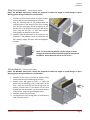
NOTE: The W3100FS wood stove is heavy. Be prepared to handle the weight to avoid damage or injury. Wearing gloves during installation is recommended. 1. Carefully lay the stove on its back on carpet or other material that will prevent damage to the finish. 2. Align the mounting tabs on the pedestal with the mounting holes in the bottom of the stove making sure that the rectangular outside air opening in the bottom rear of the pedestal is facing the back of the stove. Using the four 3/8” x 1” bolts with washers firmly tighten the pedestal to the stove. 3. Carefully stand the stove back up. If the stove is not centered on the pedestal, loosen the bolts (do not fully remove), realign the stove, and firmly retighten the bolts. NOTE: For units with the pedestal only (no ash pan or wood storage), the stove will have to be lifted straight up for pedestal installation. Do not place the unit on its side or face. Leg Assembly – Freestanding Model
NOTE: The W3100FS wood stove is heavy. Be prepared to handle the weight to avoid damage or injury. Wearing gloves during installation is recommended. 1. Carefully lay the stove on its back on carpet or other material that will prevent damage to the finish. 2. Partially insert and tighten the 3/8” x 1” bolts and washer into the mounting holes on the bottom of the stove. Align the mounting tabs on the legs with the partially inserted bolts in the bottom of the stove making sure that the washer is on the bottom portion of the leg slot. Align the legs and tighten bolts. 3. Carefully stand the stove back up. 4. The legs do have 3/8” carriage bolts in the bottom in order to level the stove. America’s Favorite Stoves Since 1980 Page 9 Chapter 3 Installation Optional Blower Installation
WARNING: Electrical Grounding Instructions. This appliance is equipped with a three‐prong (grounding) plug for your protection against shock hazard and should be plugged directly into a properly grounded three‐prong receptacle. Do not cut or remove the grounding prong from this plug. The blower kit contains a blower assembly and speed control unit. W3100 ‐ Freestanding Units WARNING: Never operate the stove without either the blower or the blower cover in place. 1. With a hammer remove the two knockouts in the rear bottom of the firebox. 2. Insert the two 1/4‐20 x 1” bolts with washer and partially tighten. 3. Hold the blower on both sides and allow the screw heads to go through the slots and move the blower to the right as much as possible. 4. Tighten bolts with 7/16” wrench. 5. Route the fan cord so that it is not coming into contact with any part if the stove. W3100 ‐ Insert Units WARNING: Never operate the stove without either the blower or the blower cover in place. 1. Remove the cover plate under the ash lip with 5/32” allen wrench. 2. Remove the top cover of blower housing by removing the 6 hex head screws holding it in place. 3. Insert the two 1/4‐20 x 1” bolts with washer and partially tighten. 4. Hold the blower on both sides and allow the screw heads to go through the slots and move the blower to the right as much as possible. 5. Tighten bolts with 7/16” wrench. 6. Route the fan cord so that it is not coming into contact with any part if the stove. America’s Favorite Stoves Since 1980 Page 10 Chapter 3 Installation Outside Air Kit – FS Pedestal Units
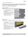
Going Out The Wall 1. Making sure that all minimum clearances are met, position the stove on the floor protection. 2. Use the two 8/32 x 3/8” thread cutting screws and attach the outside air adaptor to the pedestal as shown. 3. Attach your outside air pipe (3” ID flex pipe or equivalent ‐ purchased separately from retailer) to the adaptor in a secure manner as provided by the kit manufacturer. 4. Follow remainder of outside air kit manufacturer’s instructions. Going Through The Floor 1. Making sure that all minimum clearances are met, position the stove on the floor protection. Draw an outline around the pedestal on the floor protector. Remove the stove. 2. In the center of the outline of the pedestal foot print, cut a 4 ½” diameter hole through the floor protector and floor. Make four 1 ½” cuts in one end your outside air pipe (4” ID flex pipe or equivalent ‐ purchased separately from retailer) and fold out to make flaps. Insert the tube through the hole, cover it with a screen, and secure it to the floor protector. 3. Place the stove back on the floor protector. If the stove is to be fastened to the floor, use lag bolts long enough to penetrate well into the floor. Use the mounting holes provided inside the pedestal. 4. Install the pedestal cover by aligning the screw holes in the pedestal with the holes in the cover. America’s Favorite Stoves Since 1980 Page 11 Chapter 3 Installation Outside Air Kit – FS Leg Units
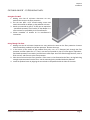
Upper Fresh Air Chamber Drawing Air Through The Floor 1. Install Upper Fresh Air Chamber to the bottom of the stove using the two ¼‐20 x 1” bolts with washers as shown in Figure A. 2. Making sure that all minimum clearances are met, position the stove on the floor protection. 3. Insert the Rectangular Air Chamber through the hole in the Upper Fresh Air Chamber and allow it to drop down until it comes into contact with the hearth pad. You may need to slightly lift the back of the stove to accomplish this. 4. Using a felt pen draw a line around the air chamber base on the hearth pad. 5. Remove the stove from the hearth pad and cut a hole just inside of the line that penetrates the hearth pad Figure A and floor. 6. Remove the hearth pad and cut a 4‐1/2” hole centered around the Rectangular Air Chamber
square hole. 7. Make four 1 ½” cuts in one end your outside air pipe (4” ID flex pipe or equivalent ‐ purchased separately from retailer) and fold out to make flaps. Insert the tube through the hole, cover it with a screen, and seal to the floor. 8. Reposition the hearth pad and the stove so that the Rectangular Air Chamber is aligned with hole in the hearth pad. 9. Secure the Rectangular Air Chamber to the Upper Fresh Air Chamber with the screw provided.
Drawing Air Through The Wall 1. Install Upper Fresh Air Chamber to the bottom of the stove using the two ¼‐20 x 1” bolts with washers as shown in Figure A. 2. Making sure that all minimum clearances are met, position the stove on the floor protection. 3. Insert the Rectangular Air Chamber through the hole in the Upper Fresh Air Chamber and allow it to drop down until it comes into contact with the hearth pad. You may need to slightly lift the back of the stove to accomplish this. This normally comes pre‐assembled. However, if you receive one that needs assembly just follow the Figure B diagram shown in Figure B. 4. Secure the Rectangular Air Chamber to the Upper Fresh Air Chamber with the screw provided. 5. Attach your outside air pipe (3” ID flex pipe or equivalent ‐ purchased separately from retailer) to the adaptor in a secure manner as provided by the kit manufacturer. 6. Follow remainder of outside air kit manufacturer’s instructions. America’s Favorite Stoves Since 1980 Page 12 Chapter 3 Installation Flashing Installation –
Insert Models
1. After installing the stove in the fireplace, pull the stove toward the hearth just a couple of inches. 2. Remove the two screws on each side of the stove using a 3/32” allen wrench. 3. With the Philips head screws provided install two screws on each side of the stove and only partially tighten. 4. Insert the side flashing over the screw head and allow to drop down. 5. Tighten Philips head screws. 6. Repeat for other side. 7. Install two Phillips Head screws in the top of each side flashing and only partially tighten. 8. Slide the top flashing onto the screws and tighten screws. 9. Push stove and flashing into fireplace so that the flashings align against the face of the hearth. Mobile or Manufactured Home Requirements
NOTE: Not approved for Canadian Mobile Home Installations. These directions only apply for mobile home installations within the United States of America. WARNING: DO NOT INSTALL IN A SLEEPING ROOM. NOTE: The outside air kit MUST be used (See “OUTSIDE AIR KIT”), and a spark arrestor may be required. Check with your local building officials. NOTE: DOUBLE WALL PIPE IS REQUIRED FOR THE EXHAUST. Single wall pipe is NOT authorized for Mobile or Manufactured Home Installations. The W3100FS must be securely fastened to the floor of the mobile (manufactured) home using the mounting bolt holes located in the pedestal of the W3100FS. Use only the holes provided. If the optional blower is used the W3100FS must be grounded to the steel chassis of the home with 8 Ga. Copper wire using a serrated or star washer to penetrate paint or protective coating to ensure grounding. CAUTION: DURING THE INSTALLATION OF THIS STOVE, DO NOT COMPROMISE THE STRUCTUARL INTEGRITY OF THE MOBILE (MANUFACTURED) HOME WALL(S), FLOOR OR CEILING. America’s Favorite Stoves Since 1980 Page 13 Chapter 3 Installation Installing the Brick Panels
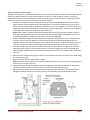
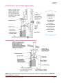
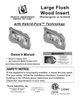
The brick panels will come already installed in the W3100. The following directions are included should you ever need to remove and re‐install the brick panels. Wearing gloves is recommended when handling the brick panels. Install the brick panels shown in figure 6 in the following order: C, B, A and F. Next remove the front secondary tube. Install the panels D with the ceriblanket above them. Replace the front secondary tube. Figure 6 America’s Favorite Stoves Since 1980 To remove the secondary air tubes you must first pull the pin out, slide the tube to the left, raise the right side of the tube up out of the bracket, then slide the tube to the right to release the left side of the tube and pull out of stove. Page 14 Chapter 3 Installation Freestanding Installation Requirements
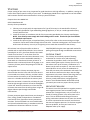
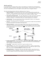
DO NOT CONNECT THIS UNIT TO A CHIMNEY FLUE SERVING ANOTHER APPLIANCE. Chimney connector must be a minimum 24 MSG black or 26 MSG blued steel (6" diameter). Chimney must be used from the first floor or wall penetration to the chimney cap. Use 6" diameter type UL 103 HT chimney from one manufacturer (do not mix brands) or code approved masonry chimney with a flue liner. Chimney connector and chimney must be fastened to the stove and each adjoining section per manufacturers instructions. Follow the chimney manufacturer's clearances and requirements. Use the chimney manufacturer's fire stops, attic guards, roof supports, and flashings when passing through a ceiling or thimble when passing through a combustible wall. No more than 180o of elbows (two 90o elbows, or two 45o & one 90o elbow, etc.). Standard residential installations may use single‐wall connector (Mobile‐Home may NOT) Standard residential installations with reduced clearance connector may use the clearance determined by the manufacturer of the connector for the connector to wall clearance or the clearance listed in this manual. Offsets must be used to maintain the stove to wall clearance. Mobile homes must use the clearances listed in this manual under "Mobile or Manufactured Home Requirements". NOTE: Additional elbows may be allowed if draft is sufficient. Whenever elbows are used the draft is adversely affected. Additional chimney height may be required to boost draft. Example Installation – Freestanding Through Roof NOTE: This appliance relies upon natural draft to operate. External forces such as wind, barometric pressure, topography, or factors of the home, may adversely affect draft. Breckwell cannot be responsible for external forces resulting in reduced performance of the stove. America’s Favorite Stoves Since 1980 Page 15 Chapter 3 Installation Example Installation – Freestanding with Exterior Factory Built Chimney NOTE: Exterior chimneys are subject to greater moisture and creosote accumulation due to the lower temperatures. An insulated chase can help to reduce these accumulations. Proper clearances to the chimney must still be maintained. America’s Favorite Stoves Since 1980 Page 16 Chapter 3 Installation Example Installation – Freestanding with Masonry or Factory Built Chimney NOTE: Most factory‐built chimney manufacturers make stainless steel chimney liners, either flexible or rigid. This provides a wide variety of installation options. Ensure that all manufacturers’ instructions for installation and support are strictly followed. America’s Favorite Stoves Since 1980 Page 17 Chapter 3 Installation Insert Installation Requirements
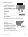
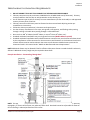
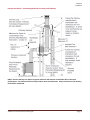
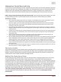
Masonry Fireplace Requirements Chimney must have a clay tile liner or a stainless steel liner (positive connection) Entire fireplace, including chimney, must be clean and undamaged. Any damage must be repaired prior to installation of the insert Chimney height: 15' minimum; 33' maximum. Entire fireplace, including chimney, must meet local building requirements Zero‐Clearance (Metal) Fireplace Requirements: Must utilize a positive (full reline – recommended method)) or direct connection (block‐off plate) Must be manufactured by one of the following manufacturers: Marco, Majestic, Heatilator, Preway, Tempco, Superior, Heat N Glo, Lennox, Martin, Monesson. The chimney must be listed per UL 127 (US), and meet type HT requirements of UL 103 (US). Factory built fireplace chimneys tested to UL 127‐1998, may be at the fireplace manufacturer’s option, tested to the same criteria as UL 103 HT requirements. If the chimney is not listed as meeting HT requirements, or if the factory built fireplace was tested prior to 1998, a full height listed chimney liner must be installed from the appliance flue collar to the chimney top. The liner must meet type HT requirements (2100oF) per UL 1777 (US). The liner must be securely attached to the insert flue collar and the chimney top. To prevent air passge to the chimney cavity of the fireplace, seal either the damper area around the chimney liner with high temperature sealant or the fireplace front with fiberglass batting. Entire fireplace, including chimney, must be clean and undamaged. Any damage must be repaired prior to installation of the insert All convection vents and louvers must be left unmodified and unobstructed. Entire fireplace, including chimney, must meet local building requirements Chimney height: 15' minimum; 33' maximum. Minimum cross section: 28.65 square inches The damper ("A") and grate ("B") must be removed (see the illustration to the right) The smoke shelf ("C"), internal baffles ("D"), screen ("E"), and metal or glass doors ("F") may be removed (if applicable) The masonry lining ("G"), insulation ("H"), and any structured rigid frame members (metal sides, floor, door frame, face of the fireplace, etc. – "I") may not be removed or altered A permanent metal warning label must be attached to the back wall of the fireplace opening stating the following: “This fireplace has been altered to accommodate a fireplace insert and should be inspected by a qualified person prior to re‐use as a conventional fireplace.” This label is available upon request. Drafting Performance This appliance relies upon natural draft to operate. External forces, such as wind, barometric pressure, topography, or factors of the home (negative pressure from exhaust fans, chimneys, air infiltration, etc.), may adversely affect draft. Breckwell cannot be responsible for external forces leading to less than optimal performance. Leveling Bolt Installation Two leveling bolts are included to level the insert if the fireplace has a stepped‐up hearth. To install, raise the rear of the insert up and insert the leveling bolts into the holes in the rear corners of the insert. Adjust the bolts until they extend the same height as the hearth steps up. After the insert is installed, fine‐tune the leveling bolts to level the insert (see the illustration). America’s Favorite Stoves Since 1980 Page 18 Chapter 3 Installation BLOCK‐OFF PLATE INSTALLATION Whenever this appliance is installed with a direct connection a block‐off plate, or other noncombustible seal‐off device (e.g. damper adapter), will need to be installed. This device is used to seal the chimney, insuring no smoke enters the home and providing the chimney system with a seal to promote draft. The directions below detail the steps for construction and installation of a block‐off plate. 1. Determine a location for the block‐off plate at the top of the firebox below the damper area (make it high enough to allow installation of the connection pipe). The location should be level and in an area where it can be mounted easily. Measure the width at the rear ("A") and front ("B") of the firebox at the height where the block‐off plate will be installed (see the illustration below). Then measure the depth of the location where the block‐off plate will be installed ("C"). NOTE: Most masonry fireplaces have square fireboxes while certain zero‐clearance (metal) fireplaces often have domed firebox tops. This makes zero‐clearance block‐off plates more difficult to install. To simplify the procedure, insulation may be used to seal the rounded edges. 2. Make a cardboard template of the measurements, but add a 2" flange to each side. This flange will be used to mount the block‐off plate to the inside of the firebox. Bend the flanges downwards on the template and place it inside the fireplace. If the template fits correctly in its planned location, go to the next step. If it does not, make a new template with the appropriate corrections until it fits correctly. 3. With the template in place, mark the location of the flue (see “Dimensions” on page 6). This location approximates the center of the flue when the insert is in place (a slight offset may occur based upon insert and block‐off plate placement). Remove the template and cut a 6 1/4" diameter hole centered on this mark. 4. Make the block‐off plate of 24 gage or thicker steel to match the template. Drill two holes in each flange for mounting the plate. 5. Mount the block‐off plate using masonry screws. NOTE: Use sheet metal screws on zero‐clearance (metal) fireplaces (screws need only be long enough to penetrate the first layer of metal). 6. Insulate the block‐off plate using high‐temperature fiberglass insulation (Ceri‐blanket® or equivalent) and furnace cement (allow the cement to dry for at least 24 hours before burning). 7. After placing the appliance and installing the pipe through the block‐off plate, use high temperature fiberglass insulation and furnace cement to seal any cracks between the pipe and block‐off plate. America’s Favorite Stoves Since 1980 Page 19 Chapter 3 Installation Example Installation – Positive Connection THIS IS THE PREFERRED INSTALLATION WHICH WILL RESULT IN THE BEST PERFORMANCE OF THE UNIT. NOTE: Most factory‐built chimney manufacturers make stainless steel chimney liners, either flexible or rigid. This provides a wide variety of installation options. Make sure to follow the manufacturer’s instructions for installation and support. NOTE: THIS INSTALLATION IS THE ONLY ONE APPROVED FOR CANADIAN INSTALLATIONS. This fireplace insert must be installed with a continuous chimney liner of 6” diameter extending from the fireplace insert to the top of the chimney. The chimney liner must conform to the Class 3 requirements of CAN/ULC‐S635, Standard for Lining Systems for Existing Masonry or Factory‐Built Chimneys and Vents, or CAN/ULS‐S640, Standard for Lining Systems for New Masonry Chimneys. NOTE: OUTSIDE AIR MAY BE REQUIRED. If adequate fresh air is not provided, you will experience an inefficient burn. For some installations (air tight homes) you may be required to provide additional air in order to achieve a clean and efficient burn. This can be accomplished by opening the ash dump door of the fireplace or other means. America’s Favorite Stoves Since 1980 Page 20 Chapter 3 Installation Example Installation – Direct Connection (Masonry Fireplace) Although this installation is acceptable, it is not the recommended installation technique. This installation has an increased potential for smoke entering the home. Example Installation – Direct Connection (Zero‐Clearance Fireplace) NOTE: Direct connections require installation of an airtight block‐off plate or damper adaptor (see Block‐off Plate Installation on page 16) America’s Favorite Stoves Since 1980 Page 21 Chapter 4 Operation OPERATING YOUR WOOD STOVE
For best efficiency and heat output, burn dry, seasoned wood only. Never burn wet wood, driftwood, wood that has been in salt water, trash, cardboard, coal, rubbish, etc. Burning fuel other than dry, seasoned wood may be illegal in some areas. Seasoned wood is wood that has been cut, split, and stored in dry, covered area in a manner that allows for free airflow around the wood for an extended period of time (6 months minimum). NOTE: During normal operation the door must remain closed. Failure to operate the stove properly can result in smoke entering the home, increased safety hazards, and may result in serious bodily injury or death. Building a Fire
1.
2.
3.
4.
5.
6.
7.
8.
Never use gasoline, gasoline‐type lantern fuel, kerosene, charcoal lighter fluid, or other similar liquids to start or ‘freshen up’ a fire in this heater. Keep all such liquids well away from the heater while in use. Do not use a grate or any other means of elevating the fire. Always build the fire on the surface of the firebrick. Stack seasoned wood in a manner that allows sufficient airflow around the wood and no closer than 3” to the secondary air tubes and 1” from glass. Pull the damper rod completely out. The damper controls the burn rate and amount of air coming in to the stove. Pulling it out allows more air in to the stove, a higher burn rate. Pushing it in lessens the air coming into the stove, a lower burn rate. Crumple up some paper and place on firebrick between the front and center of brick. Cover the paper with several pieces of kindling. For a cold chimney, one or two extra pieces of paper may be placed on top of the kindling to help establish draft. Light the paper and allow enough time for the kindling to get burning. Depending on the natural draft of your stove, the door may need to be left open slightly during this startup process. Once the kindling is burning well more wood may be added. For best results, use gradually increasing sizes of wood before adding larger pieces for longer burns. Always allow enough time for the wood to get burning well before adding larger pieces of wood. When loading wood, always be careful not to dislodge the upper brick baffle. After establishing the desired fire (about 15‐20 minutes), be sure to check the exhaust for excessive amounts of smoke. Excessive smoke indicates an improper burn rate (damper setting). Readjust if necessary and recheck again after 5‐10 minutes. The optional fan should only be used after the stove is completely reheated. The speed should be set to match the burn rate, a low burn – low fan, a high burn – high fan. Disposal of Ashes
Ashes should be placed in a metal container with a tight fitting lid. The closed container of ashes should be placed on a noncombustible surface or on the ground, well away from all combustible materials pending final disposal. If ashes are disposed of by soil burial or otherwise locally dispersed, they should be retained in the closed container until all cinders have been thoroughly cooled. Keeping The Door Glass Clean
No stove door glass stays perfectly clean. The most important factor in keeping the glass clean is to burn only well seasoned wood. Burning wet wood will make the glass dirty. The airwash system, which directs the incoming combustion air across the glass, is designed to help keep the glass clean. The airwash performs best at medium burn rates. The glass is also kept clean by the high temperatures inside the firebox. Cool temperatures in the firebox will cause condensation of the exhaust by‐products on the glass. Do not expect the glass to stay clean during longer burn times. If your glass gets very dirty during overnight burns, try preheating the stove longer before shutting the damper down. Load wood towards the rear of the stove. Keeping freshly loaded wood away from the glass will also help. This stove will self clean by burning very hot fires, but do not over fire. If the stove or chimney system glows, you are over firing. Proper burning habits and an understanding of how your stove operates will help you keep your door glass clean, but remember that no door glass will stay perfectly clean. America’s Favorite Stoves Since 1980 Page 22 Chapter 4 Operation Maximizing Your Stoves Efficiency
Heat transfer can be enhanced by slowing the rate of incoming combustion air, allowing more time for heat to be transferred in to your home. Slowing the rate of incoming air also slows the rate of exhaust going up the chimney and carrying heat away with it. To achieve this, always thoroughly preheat your stove before closing the damper. The following are some tips for getting the most out of your stove: 1. Always thoroughly preheat your stove before slowing the burn rate (closing the damper). 2. Always operate your stove as much as possible in the low to medium burn rates. 3. Temperature measurements taken from the hottest point on the stove, on the top or face, can be used to repeat burn rates. 4. Do not continually operate your stove with the damper wide open. This can damage your stove and chimney. It is a waste of wood, and is very inefficient causing excessive heat loss through the chimney. 5. Periodically go outside and check your chimney. More than a very small amount of smoke indicates wasted heat, creosote build up and pollution. 6. Do not set the damper so low as to completely extinguish the flames in the firebox. Check for at least some flames 20 minutes after setting the damper. Adjust if needed. Achieving Long, Clean Burns
It is important to realize that stove technology and design have changed over the years, as well as proper operation. In older stoves the mind set was to get the stove as hot as possible before setting the damper on low for long burns. This no longer applies to your new Breckwell stove. It is still important to have the stove hot enough to burn efficiently, but this will now take less pre‐heating than older stoves. After some initial experimentation, you will be able to determine the optimum operating temperatures for various burn rates. Breckwell wood stoves are emission tested to EPA standards with the damper fully closed for low burn rates Whether or not you should burn your stove with the damper completely closed will depend on the following factors: ∙ Moisture content and type of wood. ∙ How you load your wood. ∙ Your chimney system. ∙ The temperature of the stove. After thoroughly pre‐heating the stove, using a stove/chimney thermometer, monitor the temperature on the top of the stove. Use 325 degrees as a starting point. When the top reaches the target temperature, close the damper all the way in. If the flames go completely out, open the damper all the way and then slowly close until there is a small amount of flame. Remember to check the stove in twenty minutes after adjusting the damper as it takes this long for the stove to stabilize. There should still be some small flames on or above the wood. Try varying the target temperature in increments of 25 degrees. If the stove is burning the wood too quickly, use a lower temperature. If there are no flames in the firebox after a few minutes, use a higher temperature. You may need to burn the stove with the damper fully open for a few minutes before setting for a low burn. Never smolder a fire during a long burn. Check your chimney for large amounts of smoke as this indicates poor combustion. Experiment with different loading methods. Fresh wood should be loaded towards the rear of the firebox, while bringing half‐burned wood towards the front. If the new wood does not ignite within a few minutes, try crisscrossing the wood to allow for more airflow around the wood. CAUTION: NEVER MODIFY THE DAMPER ASSEMBLY TO INCREASE OR DECREASE AIRFLOW.
America’s Favorite Stoves Since 1980 Page 23 Chapter 5 Maintenance & Troubleshooting STOVE MAINTENANCE
TROUBLESHOOTING
Door There are a variety of high quality cleaners available that may be used to clean your brass door. Use only products specifically made for use in wood stoves when cleaning the glass. Never scrape the glass with anything or use abrasive cleaners, as pitting may occur. Never clean glass when it is hot. If door hinges need lubricating, never use oil; use only a high temperature anti‐seize compound. Avoid slamming the door or striking the glass. Never use substitute materials on the door. CAUTION: DO NOT USE THE STOVE IS THE GLASS IS CRACKED, BROKEN, OR MISSING. Ceri‐Blanket During every chimney cleaning the ceri‐blanket should be inspected. If it has become compressed or heavily stained it needs to be replaced. Gaskets Periodically check the door gasket to make sure it is not over compressed (causing the door to leak). Your Breckwell dealer can supply you with the correct gasket for replacement. Never use substitute materials. Chimney Cleaning & Inspection Before each heating season the entire chimney system, combustion chamber, and fireplace should be professionally inspected, cleaned and, if necessary, repaired. The chimney connector and chimney should be inspected at least once a month during the heating. Poor Draft If your stove is not drafting properly, the chimney may be the problem. Have the chimney relined to the proper size or extend the length of the chimney (Contact your Breckwell dealer). Also refer to the section 4.1 “Natural Draft”. Dirty Glass Burn smaller, hotter fires and make sure that the damper is not closed too far. Make sure the wood is well seasoned and not wet. (See “POOR DRAFT” above) Wood Burns Too Fast The door gasket may be leaking. Check for leaks and replace if needed. The damper rod is too far out. Stove Emits Odor Paint is curing. (See “INTRODUCTION”) Poor Heat Output Make sure the wood is well seasoned and not wet. (See “FUEL”) The stove needs to finish curing. (See “INTRODUCTION”) Smokes When Door Is Open Always fully open damper before opening door. Is the brick baffle dislodged? (See “INSTALLING THE BRICK PANELS”). Check chimney for creosote blockage. (See “CREOSOTE”) America’s Favorite Stoves Since 1980 Page 24 Chapter 5 Maintenance & Troubleshooting PROPER FUEL & STORAGE
Use only dry, natural wood in your stove. Dry, well seasoned wood will provide a good clean burn with plenty of heat and low smoke with proper airflow. Dry wood is the key to experiencing the best performance. Using green or unseasoned wood will potentially increase creosote formation and reduce your stoves efficieny. Testing Wood Moisture Split wood stored in a dry area will be fully dry within a year. This insures dry well seasoned wood. If purchasing wood for immediate use, test the wood with a moisture meter. Some experienced wood burners can measure wood moisture by knocking pieces together and listening for a clear "knock" and not a "thud". Why Dry Wood is Key Wet wood, when burned, must release water stored within the wood. This cools the fire, creates creosote, and hampers a complete burn. Ask any experienced wood burner and he or she will agree: dry wood is crucial to good performance. Wood Cutting and Storage Cut wood to length and chop into quarters. Store the wood off the ground in a covered area. Allow for airflow around the wood to dry the wood. CAUTION: DO NOT STORE WOOD WITHIN MINIMUM CLEARANCES OF THE STOVE OR WITH THE SPACE REQUIRED FOR CHARGEING AND ASH REMOVEL. FAILURE TO MAINTAIN PROPER CLEARANCES MAY RESULT IN A DANGEROUS CONDITION. America’s Favorite Stoves Since 1980 Page 25 Chapter 5 Maintenance & Troubleshooting DOOR ASSEMBLY & GLASS REPLACEMENT
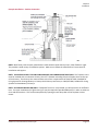
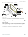
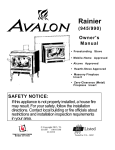
Glass Gasket Door Gasket
Glass Door Handle Shaft ½” Flat Washer Door Handle
Woodruff Key Glass Clips and Gasket Latch Cam
3/8” Hex Nut
Replacing the Glass The glass must not contact the door retainer or door shell directly. The glass gasket insulates the glass to prevent cracking. Do not over‐tighten the door retainer. The glass gasket attaches to the perimeter of the glass. Remove the screws and door retainer to access the glass. When installing, do not over‐tighten the screws. Replacing the Door Gasket The door gasket inserts into the outer groove of the door retainer. Stove gasket cement holds it in place. Before installing, remove any residual cement. Lay the gasket in place (start at the lower left corner) and cut off any excess gasket (do not stretch the gasket. The cement fully cures with heat from the stove. You may need to open and close the door repeatedly to get the gasket to seat fully. Replacing the Door Handle The door handle consists of several components. See the illustration above for a component list. America’s Favorite Stoves Since 1980 Page 26 Chapter 5 Maintenance & Troubleshooting REPLACEMENT PARTS
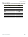
Contact an Authorized Breckwell Pellet Stove Dealer to obtain any of these parts. Never use substitute materials or components. Use of non‐approved parts can result in poor performance and safety hazards. ITEM Part # Blower Kit – All Units – Optional A‐E‐3100BLOWKIT Brick Panel Set A‐BRICK‐W31 Damper Knob C‐S‐852 Door Gasket C‐G‐050 Door Glass C‐D‐038 Door Handle Shaft CW‐D‐031 Door Handle ‐ Wood CW‐M‐250 Glass C‐D‐038 Glass Clip C‐S‐110 Glass Gasket C‐G‐033 Outside Air Kit, Pedestal – Through Wall – Optional A‐W3100‐OAK Latch Cam CW‐D‐021 Outside Air Kit, Leg – Through Floor – Optional A‐W3100LEG‐AIR Outside Air Kit, Leg – Through Wall – Optional A‐W3100LEG‐WALL Secondary Air Tube – Front (First two tubes) CW‐S‐009 Secondary Air Tube – Rear CW‐S‐009‐R Window Gasket C‐G‐033 Woodruff Key CW‐F‐031 America’s Favorite Stoves Since 1980 Page 27