1
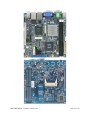
MX965GME Intel Core 2 Duo Mini-ITX Mainboard Users Manual 1st Edition – 8 November 2007 Avalue Technology Inc. FCC Statement THIS DEVICE COMPLIES WITH PART 15 FCC RULES. OPERATION IS SUBJECT TO THE FOLLOWING TWO CONDITIONS: (1) THIS DEVICE MAY NOT CAUSE HARMFUL INTERFERENCE. (2) THIS DEVICE MUST ACCEPT ANY INTERFERENCE RECEIVED INCLUDING INTERFERENCE THAT MAY CAUSE UNDESIRED OPERATION. THIS EQUIPMENT HAS BEEN TESTED AND FOUND TO COMPLY WITH THE LIMITS FOR A CLASS "A" DIGITAL DEVICE, PURSUANT TO PART 15 OF THE FCC RULES THESE LIMITS ARE DESIGNED TO PROVIDE REASONABLE PROTECTION AGAINST HARMFUL INTERFERENCE WHEN THE EQUIPMENT IS OPERATED IN A COMMERCIAL ENVIRONMENT. THIS EQUIPMENT GENERATES, USES, AND CAN RADIATE RADIO FREQUENCY ENERGY AND, IF NOT INSTALLED AND USED IN ACCORDANCE WITH THE INSTRUCTION MANUAL, MAY CAUSE HARMFUL INTERFERENCE TO RADIO COMMUNICATIONS. OPERATION OF THIS EQUIPMENT IN A RESIDENTIAL AREA IS LIKELY TO CAUSE HARMFUL INTERFERENCE IN WHICH CASE THE USER WILL BE REQUIRED TO CORRECT THE INTERFERENCE AT HIS OWN EXPENSE. Copyright Notice Copyright © 2007 Avalue Technology Inc., ALL RIGHTS RESERVED. No part of this document may be reproduced, copied, translated, or transmitted in any form or by any means, electronic or mechanical, for any purpose, without the prior written permission of the original manufacture Trademark Acknowledgement Brand and product names are trademarks or registered trademarks of their respective Owners MX965GME USERS MANUAL PAGE |2 Disclaimer Avalue Technology Inc. reserves the right to make changes, without notice, to any product, including circuits and/or software described or contained in this manual in order to improve design and/or performance. Avalue Technology assumes no responsibility or liability for the use of the described product(s), conveys no license or title under any patent, copyright, or masks work rights to these products, and makes no representations or warranties that these products are free from patent, copyright, or mask work right infringement, unless otherwise specified. Applications that are described in this manual are for illustration purposes only. Avalue Technology Inc. makes no representation or warranty that such application will be suitable for the specified use without further testing or modification. Life Support Policy Avalue Technology’s PRODUCTS ARE NOT FOR USE AS CRITICAL COMPONENTS IN LIFE SUPPORT DEVICES OR SYSTEMS WITHOUT THE PRIOR WRITTEN APPROVAL OF Avalue Technology Inc. As used herein: 1. Life support devices or systems are devices or systems which, (a) are intended for surgical implant into body, or (b) support or sustain life and whose failure to perform, when properly used in accordance with instructions for use provided in the labeling, can be reasonably expected to result in significant injury to the user. 2. A critical component is any component of a life support device or system whose failure to perform can be reasonably expected to cause the failure of the life support device or system, or to affect its safety or effectiveness. A Message to the Customer Avalue Customer Services Each and every Avalue’s product is built to the most exacting specifications to ensure reliable performance in the harsh and demanding conditions typical of industrial environments. Whether your new Avalue device is destined for the laboratory or the factory floor, you can be assured that your product will provide the reliability and ease of operation for which the name Avalue has come to be known. Your satisfaction is our primary concern. Here is a guide to Avalue’s customer services. To ensure you get the full benefit of our services, please follow the instructions below carefully. MX965GME USERS MANUAL PAGE |3 Technical Support We want you to get the maximum performance from your products. So if you run into technical difficulties, we are here to help. For the most frequently asked questions, you can easily find answers in your product documentation. These answers are normally a lot more detailed than the ones we can give over the phone. So please consult the user’s manual first. To receive the latest version of the user’s manual; please visit our Web site at: http://www.avalue.com.tw/ If you still cannot find the answer, gather all the information or questions that apply to your problem, and with the product close at hand, call your dealer. Our dealers are well trained and ready to give you the support you need to get the most from your Avalue’s products. In fact, most problems reported are minor and are able to be easily solved over the phone. In addition, free technical support is available from Avalue’s engineers every business day. We are always ready to give advice on application requirements or specific information on the installation and operation of any of our products. Please do not hesitate to call or email us. Headquarters Avalue Technology Inc. 7F, 228, Lian-cheng Road, Chung Ho City, Taipei, Taiwan Tel : +886-2-8226-2345 Fax : +886-2-8226-2777 http://www.avalue.com.tw E-mail: [email protected] US Branch Office Avalue Technology Inc. Suite 210, 200 Tornillo Way, Tinton Falls, NJ 07712 USA Tel: +1-732-578-0200 Fax: +1-732-578-0250 http://www.avalue.com.tw E-mail: [email protected] Europe Branch Office Avalue Europe A/S Nordre Strandvej 13, 3480 Fredensborg, Denmark Tel : +45-7025-0310 Fax : +45-4975-5026 http://www.avalue.com.tw E-mail: [email protected] China Branch Office Avalue Technology Shanghai Inc. Room 909, 9F, Section B, No.900, Yisan Road, Caohejing Hi-tech Park, Shanghai 200233, China Tel : +86-21-5423-4170 Fax : +86-21-5423-4171 http://www.avalue.com.tw E-mail: [email protected] MX965GME USERS MANUAL PAGE |4 Product Warranty Avalue warrants to you, the original purchaser, that each of its products will be free from defects in materials and workmanship for two years from the date of purchase. This warranty does not apply to any products which have been repaired or altered by persons other than repair personnel authorized by Avalue, or which have been subject to misuse, abuse, accident or improper installation. Avalue assumes no liability under the terms of this warranty as a consequence of such events. Because of Avalue’s high quality control standards and rigorous testing, most of our customers never need to use our repair service. If any of Avalue’s products is defective, it will be repaired or replaced at no charge during the warranty period. For out-of-warranty repairs, you will be billed according to the cost of replacement materials, service time, and freight. Please consult your dealer for more details. If you think you have a defective product, follow these steps: 1. Collect all the information about the problem encountered. (For example, CPU type and speed, Avalue’s products model name, hardware & BIOS revision number, other hardware and software used, etc.) Note anything abnormal and list any on-screen messages you get when the problem occurs. 2. Call your dealer and describe the problem. Please have your manual, product, and any helpful information available. 3. If your product is diagnosed as defective, obtain an RMA (return material authorization) number from your dealer. This allows us to process your good return more quickly. 4. Carefully pack the defective product, a complete Repair and Replacement Order Card and a photocopy proof of purchase date (such as your sales receipt) in a shippable container. A product returned without proof of the purchase date is not eligible for warranty service. 5. Write the RMA number visibly on the outside of the package and ship it prepaid to your dealer. MX965GME USERS MANUAL PAGE |5 Table of Contents FCC Statement Copyright Notice Disclaimer Life Support Technical Support Product Warranty Chapter 1: Product Overview Specifications Layout Chapter 2: Hardware Setup Component Location CPU Memory Power Supply Back Panel Connectors Jumpers Expansion Chapter 3: BIOS Setup Entering Setup Menu Advanced Boot Security Chipset Exit MX965GME USERS MANUAL 2 2 3 3 4 5 8 10 12 13 14 15 16 18 26 27 30 32 34 45 49 50 54 PAGE |6 Chapter 1 Getting Started Thank you for choosing the MX965GME Mini ITX mainboard from Avalue. Based on the innovative Intel® GME965 & ICH8M controllers for optimal system efficiency, the MX965GME accommodates the latest Intel® Core 2 Duo/Celeron® M 5XX series processors in Socket P and supports two 240-pin 533/667MHz DDRII DIMM to provide the maximum of 4GB memory capacity. In the entry-level and mid-range market segment, the MX965GME can provide a high-performance solution for today’s front-end and general purpose workstation, as well as in the future. MX965GME USERS MANUAL PAGE |7 Mainboard Specifications Processor - Intel Core 2 Duo/Celeron M 5xx CPU in Socket P - Supports 3-pin CPU fan pin-header with Fan Speed Control - Supports Intel Dual Core Technology to 533/800MHz and up Supported FSB - 533/800MHz Chipset - North Bridge: Intel GM965/GME965 chipset - South Bridge: Intel ICH8M chipset Memory - DDR2 533/667 SDRAM (4GB Max) - 2 DDR2 DIMM slots (240pin / 1.8V) LAN - Supports 2 Gb Ethernet by Intel 82573L & 82566DC Audio - HDA Codec by Realtek ALC888 7.1 channel - Compliant with Azalia 1.0 specs - 6 watt amplifier IDE - 1 IDE port by ICH8M - Supports Ultra DMA 66/100 mode - Supports PIO, Bus Master operation mode SATA - SATA II ports by ICH8M - Supports two SATA II devices - Supports storage and data transfers at up to 300MB/s Connectors Back Panel - 1 HDMI connector - 2 RJ-45 LAN jacks and 4 USB 2.0 ports - 1 D-Sub VGA and 1 DVI connector - 1 serial port - 1 PS2 keyboard/mouse port - 3 audio jacks MX965GME USERS MANUAL PAGE |8 Connectors (Cont.) Onboard Connectors - 2 USB 2.0 connectors (4 ports) - 1 parallel port connector - 1 applifer connector (4-pin) - 1 LVDS connector - 1 TV-out connector - 1 digital I/O connector (16GPIO) - 1 serial port connector - 1 front panel connector Expansion - 1 PCI Express x4 slot (optional) - 1 Mini PCI-E slot - 1 PCI 32-bit/33MHz slot - 1 CF socket Form Factor - Mini ITX: 170mm x 170mm Mounting - 4 mounting holes Environment Storage Temperature - Temperature: -20 O C ~ 80 O C - Humidity: 0% RH ~ 95% RH Operation Temperature - Temperature: 0 O C ~ 55 O C - Humidity: 0% RH ~ 85% RH MX965GME USERS MANUAL PAGE |9 MX965GME USERS MANUAL P A G E | 10 Chapter 2 Hardware Setup This chapter provides you with the information about hardware setup procedures. While doing the installation, be careful in holding the components and follow the installation procedures. For some components, if you install in the wrong orientation, the components will not work properly. Use a grounded wrist strap before handling computer components. Static electricity may damage the components. MX965GME USERS MANUAL P A G E | 11 MX965GME J5 JAUD2 JAMP1 PCI 1 JLVDS1 JSPI2 JTV1 CPU FAN J4 SYS FAN J6 JBAT1 F_USB1 & F_USB2 ATX Power J7 SATA 1,2 MX965GME USERS MANUAL IDE1 JCF_SEL1 JLPT1 COM2 JCASE1 P A G E | 12 CPU & Cooler Installation for Socket P 1. Locate the CPU socket on the mainboard. 2. Place the CPU on top of the socket. Make sure to align the gold arrow on the CPU with the arrow key on the socket. 3. Push the CPU down until its pins securely fit into the socket. 4. On the front end of the CPU socket is a locking mechanism designed into the form of a screw head. Make sure that you actuate or deactuate this mechanism with a screwdriver before and after installing the CPU. MX965GME USERS MANUAL P A G E | 13 Memory The DIMM slots are intended for system memory modules. DDR2 240-pin,1.8V Installing DDR2 Modules 1. The memory module has only one notch on the center and will only fit in the right orientation. 2. Insert the memory module vertically into the DIMM slot. Then push it in until the golden finger on the memory module is deeply inserted in the DIMM slot. NOTE: You can barely see the golden finger if the memory module is properly inserted in the DIMM slot. 3. The plastic clip at each side of the DIMM slot will automatically close. MX965GME USERS MANUAL P A G E | 14 Power Supply ATX 20-Pin System Power Connector: ATX1 This connector allows you to connect to an ATX power supply. To connect to the ATX power supply, make sure the plug of the power supply is inserted in the proper orientation and the pins are aligned. Then push down the power supply firmly into the connector. NOTE: Power supply of 350watts (and above) is highly recommended for system stability. MX965GME USERS MANUAL P A G E | 15 Audio LAN21 USB LAN2 USB DVI COM1 HDMI VGA Mouse Keyboard Back Panel I/O Mouse/Keyboard The standard PS/2® mouse/keyboard DIN connector is for a PS/2® mouse/keyboard. Serial Port The serial port is a 16550A high speed communications port that sends/ receives 16 bytes FIFOs. You can attach a serial mouse or other serial devices directly to the connector. VGA Port The DB15-pin female connector is provided for monitor. USB Port The USB (Universal Serial Bus) port is for attaching USB devices such as keyboard, mouse, or other USB-compatible devices. LAN The standard RJ-45 LAN jack is for connection to the Local Area Network (LAN). You can connect a network cable to it. MX965GME USERS MANUAL P A G E | 16 Audio Ports These audio connectors are used for audio devices. You can differentiate the color of the audio jacks for different audio sound effects. Line-In (Blue) - Line In / Side-Surround Out in 7.1 channel mode, is used for external CD player, tape player or other audio devices. Line-Out (Green) - Line Out, is a connector for speakers or headphones. Mic (Pink) - Mic, is a connector for microphones. HDMI and DVI Ports This The HDMI and DVI ports are for digital video output. Note: It is not recommended to use a HDMI-to-DVI adaptor on HDMI port MX965GME USERS MANUAL P A G E | 17 Connectors Chassis Intrusion Connector: JCASE1 This connector connects to the chassis intrusion switch cable. If the chassis is opened, the chassis intrusion mechanism will be activated. The system will record this status and show a warning message on the screen. To clear the warning, you must enter the BIOS utility and clear the record. IDEConnector: IDE1 This connector supports IDE hard disk drives, optical disk drives and other IDE devices. NOTE: If you install two IDE devices on the same cable, you must configure the drives separately to master / slave mode by setting jumpers. Refer to IDE device’s documentation supplied by the vendors for jumper setting instructions. MX965GME USERS MANUAL P A G E | 18 Digital IO Connector: J4 The J4 is designed to connect the General-Purpose Input/Output (GPIO) peripheral module. Serial ATA II Connector: SATA1, SATA2 This connector is a high-speed Serial ATA II interface port. Each connector can connect to one Serial ATA II device. NOTE: Please do not fold the Serial ATA cable into 90-degree angle. Otherwise, data loss may occur during transmission. MX965GME USERS MANUAL P A G E | 19 Audio Amplifier Connector: JAMP1 The JAMP1 is used to connect audio amplifiers to enhance audio performance. SPI Flash ROM Connector: JSPI2 This connector is used to flash SPI flash ROM. MX965GME USERS MANUAL P A G E | 20 Fan Power Connectors: CPUFAN1, SYSFAN1 The fan power connectors support system cooling fan with +12V. When connecting the wire to the connectors, always note that the red wire is the positive and should be connected to the +12V; the black wire is Ground and should be connected to GND. If the mainboard has a System Hardware Monitor chipset on-board, you must use a specially designed fan with speed sensor to take advantage of the CPU fan control. NOTE: Please refer to the recommended CPU fans at Intel® official website or consult the vendors for proper CPU cooling fan. Front Panel Connector: JFP1 The mainboard provides one front panel connector for electrical connection to the front panel switches and LEDs. The JFP1 is compliant with Intel® Front Panel I/O Connectivity Design Guide. MX965GME USERS MANUAL P A G E | 21 TV-Out Connector: JTV1 This connector is for you to attach an optional TV-Out bracket that offers two types of TV-Out connectors: S-Video and RCA Composite connectors. Select the appropriate one to connect the standard television or the HDTV (High-Definition Television). NOTE: Please note that the TV-Out bracket can connect to one TV only. Users have to choose either the RCA Composite or the S-Video to connect. Simultaneously connecting two TVs to this bracket is prohibited and may lead to the malfunction of the TVs. MX965GME USERS MANUAL P A G E | 22 LVDS Flat Panel Connector: JLVDS1 The LVDS (Low Voltage Differential Signal) connector provides a digital interface typically used with flat panels. MX965GME USERS MANUAL P A G E | 23 Front USB Connector: F_USB1, F_USB2 This connector, compliant with Intel® I/O Connectivity Design Guide, is ideal for connecting highspeed USB interface peripherals such as USB HDD, digital cameras, MP3 players, printers, modems and the like. NOTE: The pins of VCC and GND must be connected correctly to avoid possible damage. MX965GME USERS MANUAL P A G E | 24 Serial Port Connector: COM 2 This connector is a 16550A high speed communications port that sends/receives 16 bytes FIFOs. You can attach a serial device to it through the optional serial port bracket. Parallel Port Connector: JLPT1 The mainboard provides a 26-pin header for connection to an optional parallel port bracket. The parallel port is a standard printer port that supports Enhanced Parallel Port (EPP) and Extended Capabilities Parallel Port (ECP) mode. MX965GME USERS MANUAL P A G E | 25 Jumpers Inverter Power/ Control Connector: J7 Provide the Power and brightness control to the inverter and output to LVDS panel. COM Port Power Jumpers: J5, J6 These jumpers specify the operation voltage of the onboard serial ports. Clear CMOS Jumper: JBAT1 There is a CMOS RAM onboard that has a power supply from external battery to keep the data of system configuration. With the CMOS RAM, the system can automatically boot OS every time it is turned on. If you want to clear the system configuration, set this jumper to clear data. NOTE: You can clear CMOS by shorting 1-2 pin while the system is off. Then return to 2-3 pin position. Avoid clearing the CMOS while the system is on; it will damage the mainboard. MX965GME USERS MANUAL P A G E | 26 Expansion PCI (Peripheral Component Interconnect) Express Slot The PCI Express slot supports PCI Express interface expansion cards. The PCI Express x 4 slot supports up to 2.0 GB/s transfer rate. The CON1 is Mini PCI-E connector for wireless LAN, TV tuner, and Robson NAND Flash. PCI (Peripheral Component Interconnect) Slot The PCI slot supports LAN card, SCSI card, USB card, and other add-on cards that comply with PCI specifications. PCI Interrupt Request Routing The IRQ, acronym of interrupt request line and pronounced I-R-Q, are hardware lines over which devices can send interrupt signals to the microprocessor. The PCI IRQ pins are typically connected to the PCI bus pins as follows: NOTE: When adding or removing expansion cards, make sure that you unplug the power supply first. Meanwhile, read the documentation for the expansion card to configure any necessary hardware or software settings for the expansion card, such as jumpers, switches or BIOS configuration. MX965GME USERS MANUAL P A G E | 27 Compact Flash Card Slot: CF1 This Compact Flash slot shares one channel of the IDE controller. You can install one Compact Flash type I / type II device. NOTE: The CF1 slot and the IDE1 connector shares and uses the same channel. CF1 and IDE1 can support up to 2 IDE devices without CF device or 1 IDE device with 1 CF device. * If you install two IDE devices, you must configure the second drive to Slave mode by setting its jumper. Refer to the hard disk documentation supplied by hard disk vendors for jumper setting instructions. * If you install one IDE device with ATA133 IDE cable and one CF device, you must configure the CF drive to Master mode by setting jumper JCF_SEL1. CF only supports Master mode by using the ATA133 IDE cable. * CF only supports Slave mode by using ATA33 IDE cable. MX965GME USERS MANUAL P A G E | 28 Chapter 3 BIOS Setup This chapter provides information on the BIOS Setup program and allows you to configure the system for optimum use. You may need to run the Setup program when: An error message appears on the screen during the system booting up, and requests you to run SETUP. You want to change the default settings for customized features. MX965GME USERS MANUAL P A G E | 29 Entering Setup Power on the computer and the system will start POST (Power On Self Test) process. When the message below appears on the screen, press <Del> key to enter Setup. Press Del to enter SETUP If the message disappears before you respond and you still wish to enter Setup, restart the system by turning it OFF and On or pressing the RESET button. You may also restart the system by simultaneously pressing <Ctrl>, <Alt>, and <Delete> keys. NOTE: 1. The items under each BIOS category described in this chapter are under continuous update for better system performance. Therefore, the description may be slightly different from the latest BIOS and should be held for reference only. 2. Upon boot-up, the 1st line appearing after the memory count is the BIOS version. It is usually in the format: MX965GME #70551 BIOS V1.0 where: 1st word refers to model name. 2nd word refers to the model number. V1.0 refers to the BIOS version. Control Keys MX965GME USERS MANUAL P A G E | 30 Getting Help After entering the Setup menu, the first menu you will see is the Main Menu. Main Menu The main menu lists the setup functions you can make changes to. You can use the arrow keys ( to select the item. The on-line description of the highlighted setup function is displayed at the bottom of the screen. Sub-Menu If you find a right pointer symbol (as shown in the right view) appears to the left of certain fields that means a sub-menu can be launched from this field. A sub-menu contains additional options for a field parameter. You can use arrow keys (to highlight the field and press <Enter> to call up the sub-menu. Then you can use the control keys to enter values and move from field to field within a sub-menu. If you want to return to the main menu, just press the <Esc >. General Help <F1> The BIOS setup program provides a General Help screen. You can call up this screen from any menu by simply pressing <F1>. The Help screen lists the appropriate keys to use and the possible selections for the highlighted item. Press <Esc> to exit the Help screen. MX965GME USERS MANUAL P A G E | 31 Menu Bar Main Use this menu for basic system configurations, such as time, date etc. Advanced Use this menu to set up the items of special enhanced features. Boot Use this menu to specify the priority of boot devices. Security Use this menu to set supervisor and user passwords. Chipset This menu controls the advanced features of the onboard Northbridge and Southbridge. Exit This menu allows you to load the BIOS default values or factory default settings into the BIOS and exit the BIOS setup utility with or without changes. MX965GME USERS MANUAL P A G E | 32 Main AMI BIOS, Processor, System Memory These items show the firmware and hardware specifications of your system. Read only. System Time The time format is <Hour> <Minute> <Second>. System Date The date format is <Day>, <Month> <Date> <Year>. MX965GME USERS MANUAL P A G E | 33 Advanced CPU Configuration These items show the advanced specifications of your CPU. Read only. MX965GME USERS MANUAL P A G E | 34 IDE Configuration ATA/IDE Configuration This setting specifies the modes of the PATA & SATA ports. Configure SATA as This setting specifies the function of the on-chip SATA controller. MX965GME USERS MANUAL P A G E | 35 Primary/Secondary/Third/Fourth IDE Master/Slave Type LBA/Large Mode Block (Multi-Sector Transfer) PIO Mode DMA Mode S.M.A.R.T. 32 Bit Data Transfer Press PgUp/<+> or PgDn/<-> to select [Manual], [None] or [Auto] type. Note that the specifications of your drive must match with the drive table. The hard disk will not work properly if you enter improper information for this category. If your hard disk drive type is not matched or listed, you can use [Manual] to define your own drive type manually. Enabling LBA causes Logical Block Addressing to be used in place of Cylinders, Heads and Sectors Any selection except Disabled determines the number of sectors transferred per block Indicates the type of PIO (Programmed Input/Output) Indicates the type of Ultra DMA This allows you to activate the S.M.A.R.T. (Self-Monitoring Analysis & Reporting Technology) capability for the hard disks. S.M.A.R.T is a utility that monitors your disk status to predict hard disk failure. This gives you an opportunity to move data from a hard disk that is going to fail to a safe place before the hard disk becomes offline. Enables 32-bit communication between CPUand IDEcard MX965GME USERS MANUAL P A G E | 36 Super IO Configuration Serial Port 1 / 2 Address Select an address and a corresponding interrupt for the serial port 1/2. Parallel Port Address This setting specifies the I/O port address and IRQ of the onboard parallel port. Chassis Intrusion The field enables or disables the feature of recording the chassis intrusion status and issuing a warning message if the chassis is once opened. To clear the warning message, set the field to [Reset]. The setting of the field will automatically return to [Enabled] later. MX965GME USERS MANUAL P A G E | 37 Hardware Health Configuration System 1 / 2 Temperature, CPU Temperature, CPUFAN Speed, Vcore, AVCC, 3VCC, +12V, 5V, VSB, VBAT These items display the current status of all of the monitored hardware devices/ components such as CPU voltage, temperatures and all fans’ speeds. CPUFAN0 / CPUFAN1 Mode Setting These settings specify the operation mode of the CPU fans. CPUFAN0 / CPUFAN1 PWM Control These settings control the PWM duty cycle of the CPU fans. MX965GME USERS MANUAL P A G E | 38 ACPI Configuration Suspend Mode This item specifies the power saving modes for ACPI function. If your operating system supports ACPI, you can choose to enter the Standby mode in S1 (POS) or S3 (STR) fashion through the setting of this field. Options are: [S1 (POS)] The S1 sleep mode is a low power state. In this state, no system context is lost (CPU or chipset) and hardware maintains all system context. [S3 (STR)] The S3 sleep mode is a lower power state where the information of system configuration and open applications/files is saved to main memory that remains powered while most other hardware components turn off to save energy. The information stored in memory will be used to restore the system when a “wake up” event occurs. USB Device Wakeup from S3/S4 This setting allows the activity of the USB device to wake up the system fromS3/S4 sleep state. MX965GME USERS MANUAL P A G E | 39 APM Configuration Power Management/APM Setting to [Enabled] will activate an Advanced Power Management (APM) device to enhance Max Saving mode and stop CPU internal clock. Power Button Mode This setting controls the operation of the power button. Resume On LAN This field specifies whether the system will be awakened from power saving modes when activity or input signal of onboard LAN is detected. Resume On PME# When setting to [Enabled], this setting allows your system to be awakened from the power saving modes through any event on PME (Power Management Event). Resume On RTC Alarm When [Enabled], you can set the date and time at which the RTC (real-time clock) alarm awakens the system from suspend mode. MX965GME USERS MANUAL P A G E | 40 Intel Robson Configuration Intel Robson Robson is the code name for a new Intel platform technology that uses nonvolatile memory (Flash memory) to increase system responsiveness, make multi-tasking faster, and extend battery life. Intel Robson technology is poised to eliminate many of the bottlenecks associated with HDD latency. By enabling the majority of application workload to be written and read from a system cache instead of the HDD, Robson will offer users of mobile computers built on the Santa Rosa platform significantly increased performance -- particularly in application load and run time, the speed in which systems resume operation after hibernation or boot, and in system-level power usage. MX965GME USERS MANUAL P A G E | 41 Remote Access Configuration Remote Access This field allows you to Enabled or Disabled Remote Access for console redirection via serial ports. Set the desired port and setting in each field. MX965GME USERS MANUAL P A G E | 42 Trusted Computing TCG/TPM Support This setting controls the Trusted Platform Module (TPM) designed by the Trusted Computing Group (TCG). TPMs are special-purpose integrated circuits (ICs) built into a variety of platforms to enable strong user authentication and machine attestation—essential to prevent inappropriate access to confidential and sensitive information and to protect against compromised networks. MX965GME USERS MANUAL P A G E | 43 USB Configuration Legacy USB Support Set to [Enabled] if you need to use any USB 1.1/2.0 device in the operating system that does not support or have any USB 1.1/2.0 driver installed, such as DOS and SCO Unix. USB 2.0 Controller Mode This setting specifies the operation mode of the onboard USB 2.0 controller. Hot plug USB FDD Support Set to [Enabled] if your need to use a hot plug USB-interfaced FDD in the operating system that does not support or have any USB driver installed, such as DOS and SCO Unix. MX965GME USERS MANUAL P A G E | 44 Boot Boot Settings Configuration MX965GME USERS MANUAL P A G E | 45 Quick Boot Enabling this setting will cause the BIOS power-on self test routine to skip some of its tests during bootup for faster system boot. Quiet Boot This BIOS feature determines if the BIOS should hide the normal POST messages with the motherboard or system manufacturer's full-screen logo. When it is enabled, the BIOS will display the full-screen logo during the boot-up sequence, hiding normal POST messages. When it is disabled, the BIOS will display the normal POST messages, instead of the full-screen logo. Please note that enabling this BIOS feature often adds 2-3 seconds of delay to the booting sequence. This delay ensures that the logo is displayed for a sufficient amount of time. Therefore, it is recommended that you disable this BIOS feature for a faster boot-up time. Add On ROM Display Mode This item is used to determine the display mode when an optional ROM is initialized during POST. When set to [Force BIOS], the display mode used by AMI BIOS is used. Select [Keep Current] if you want to use the display mode of optional ROM. Bootup Num-Lock This setting is to set the Num Lock status when the system is powered on. Setting to [On] will turn on the Num Lock key when the system is powered on. Setting to [Off] will allow users to use the arrow keys on the numeric keypad. PS/2 Mouse Support Select [Enabled] if you need to use a PS/2-interfaced mouse in the operating system. Wait For ‘F1’ If Error When this setting is set to [Enabled] and the boot sequence encounters an error, it asks you to press F1. If disabled, the system continues to boot without waiting for you to press any keys. Hit ‘DEL’ Message Display Set this option to [Disabled] to prevent the message as follows: Hit Del if you want to run setup It will prevent the message from appearing on the first BIOS screen when the computer boots. Set it to [Enabled] when you want to run the BIOS Setup Utility. Interrupt 19 Capture Interrupt 19 is the software interrupt that handles the boot disk function. When enabled, this BIOS feature allows the ROM BIOS of these host adaptors to "capture" Interrupt 19 during the boot process so that drives attached to these adaptors can function as bootable disks. In addition, it allows you to gain access to the host adaptor's ROM setup utility, if one is available. When disabled the ROM BIOS of these host adaptors will not be able to "capture" Interrupt 19. Therefore, you will not be able to boot operating systems from any bootable disks attached to these host adaptors. Nor will you be able to gain access to their ROM setup utilities. Flash Write Protection Select [Enabled] if you need to program data into the flash chip. Select [Disabled] if you need to protect the data from being overwritten. MX965GME USERS MANUAL P A G E | 46 Chassis Instruction Select [Enabled] to enable the chassis instruction function. Select [Disabled] to disable the chassis instruction function. Select [Reset] to clear the chassis instruction status. Boot Device Priority 1st Boot Device The items allow you to set the sequence of boot devices where BIOS attempts to load the disk operating system. First press <Enter> to enter the sub-menu. Then you may use the arrow keys (to select the desired device, then press <+>, <-> or <PageUp>, <PageDown> key to move it up/down in the priority list. MX965GME USERS MANUAL P A G E | 47 Removable Drives 1st Drive This setting allows users to set the priority of the removable devices. First press <Enter> to enter the sub-menu. Then you may use the arrow keys ( ) to select the desired device, then press <+>, <-> or <PageUp>, <PageDown> key to move it up/down in the priority list. MX965GME USERS MANUAL P A G E | 48 Security Supervisor Password / Change Supervisor Password Supervisor Password controls access to the BIOS Setup utility. These settings allow you to set or change the supervisor password. User Password / Change User Password User Password controls access to the system at boot. These settings allow you to set or change the user password. MX965GME USERS MANUAL P A G E | 49 Chipset MX965GME USERS MANUAL P A G E | 50 North Bridge Configuration Boot Graphics Adapter Priority This item specifies which VGA card is your primary graphics adapter. Internal Graphics Mode Select The field specifies the size of system memory allocated for video memory. PEG Port This setting allows you to select whether to use the onchip graphics processor or the PCI Express card. When set to [Auto], the BIOS checks to see if a PCI Express graphics card is installed. If it detects that a PCI Express graphics card is present, the motherboard boots up using that card. Otherwise, it defaults to the onboard graphics processor. PEG Force X1 This BIOS feature allows you to convert a PCI Express X4 slot into a PCI Express X1 slot. When [Enabled], the PCI Express X4 slot will be forced to run in the PCI Express X1 mode. When [Disabled], the PCI Express X4 slot will be allowed to run in its normal PCI Express X4 mode. If you have a PCI Express X4 card installed in your system, you should disable this BIOS feature. This allows for optimal performance of the card by ensuring maximum transfer rates between the card and the motherboard. But if you need to install a PCI Express X1 card into the PCI Express X4 slot, you should enable this BIOS feature to ensure maximum compatibility. MX965GME USERS MANUAL P A G E | 51 Video Function Configuration DVMT Mode Select Intel's Dynamic Video Memory Technology (DVMT) allows the system to dynamically allocate memory resources according to the demands of the system at any point in time. The key idea in DVMT is to improve the efficiency of the memory allocated to either system or graphics processor. It is recommended that you set this BIOS feature to DVMT Mode for maximum performance. Setting it to DVMT Mode ensures that system memory is dynamically allocated for optimal balance between graphics and system performance. DVMT/FIXED Memory When set to DVMT/FIXED Mode, the graphics driver will allocate a fixed amount of memory as dedicated graphics memory, as well as allow more system memory to be dynamically allocated between the graphics processor and the operating system. Boot Display Device Use the field to select the type of device you want to use as the display(s) of the system. Flat Panel Type This setting allows you to set your preferences for the flat panel display device. MX965GME USERS MANUAL P A G E | 52 South Bridge Configuration USB Functions This setting specifies the function of the onboard USB controller. USB 2.0 Controller Set to [Enabled] if you need to use any USB 2.0 device in the operating system that does not support or have any USB 2.0 driver installed, such as DOS and SCO Unix. GbE Controller This setting disables/enables the onboard Gigabit Ethernet controller. GbE LAN Boot When [Enabled], the BIOS attempts to boot from a LAN boot image before it attempts to boot from a local storage device. GbE Wake Up From S5 This field specifies whether the system will be awakened from the S5 power saving mode when activity or input signal of onboard LAN is detected. HDA Controller This setting controls the High Definition Audio interface integrated in the Southbridge. MX965GME USERS MANUAL P A G E | 53 Exit Save Changes and Exit Save changes to CMOS and exit the Setup Utility. Discard Changes and Exit Abandon all changes and exit the Setup Utility. Discard Changes Abandon all changes and continue with the Setup Utility. Load Optimal Defaults Use this menu to load the default values set by the mainboard manufacturer specifically for optimal performance of the mainboard. Load Failsafe Defaults Use this menu to load the default values set by the BIOS vendor for stable system performance. MX965GME USERS MANUAL P A G E | 54 MX965GME USERS MANUAL P A G E | 55