1
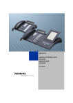
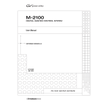
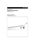
E SERIES VoIP
USER GUIDE
For E100IP, E100IPLBY, E100IPTRM, E200IP, E200IPTRM,
E103IP, E103IP RediDock, E203IP, E203IP RediDock
Important Safety Instructions
When using your telephone equipment, basic
safety precautions should always be followed to
reduce the risk of fire, electric shock, and injury
to persons, including the following:
1.Read and understand all instructions.
2.Follow all warnings and instructions marked
on the product.
3.Unplug the product from the wall outlet
before cleaning. Do not use liquid cleaner
or aerosol cleaners. Use a damp cloth for
cleaning.
4.Do not use this product near water—for
example, near a bathtub, wash bowl,
kitchen sink or laundry tub, in a wet
basement, or near a swimming pool.
5.Do not place this product on an unstable
cart, stand, or table. The product may fall,
causing serious damage to the product.
6.Slots and openings in the cabinet and
the back or bottom are provided for
ventilation, to protect it from overheating.
These openings must not be blocked or
covered. The openings should never be
blocked by placing the product on the bed,
sofa, rug, or any other similar surface.
This product should never be place near
or over a radiator or heat register. This
product should not be placed in a built-in
installation unless proper ventilation is
provided.
7.Never push objects of any kind into this
product through cabinet slots as they may
touch dangerous voltage points or short
out parts that could result in a risk of fire
or electric shock. Never spill liquid of any
kind on the product.
8.To reduce the risk of electric shock do
not disassemble this product. Take it to a
qualified service facility if service or repair
work is required. Opening or removing
covers may expose you to dangerous
2
voltages or other risks. Incorrect
reassembly can cause electric shock when
the appliance is subsequently used.
9.Unplug this product from the wall outlet
and refer servicing to qualified service
personnel under the following conditions:
– When the power supply cord or plug is
damaged or frayed.
– If liquid has been spilled into the
product.
– If the product has been exposed to rain
or water.
– If the product does not operate normally
by following the operating instructions.
Adjust only those controls that are
covered by the operating instructions, as
improper adjustment of other controls
may result in damage and may require
extensive work by a qualified technician
to restore the product to normal
operation.
– If the product has been dropped or the
cabinet has been damaged.
– If the product exhibits a distinct change
in performance.
10.Avoid using a telephone (other than a
cordless type) during an electrical storm.
There may be a remote risk of electric
shock from lightning.
11.Do not use the telephone to report a gas
leak in the vicinity of the leak.
PLEASE SAVE THESE INSTRUCTIONS.
FCC Interference Information
This device complies with Part 15 of the FCC
Rules. Operation is subject to the following two
conditions:
1.This device may not cause harmful
interference.
2.This device must accept any interference
received, including interference that may
cause undesired operation.
www.teledex.com E SERIES VoIP USER GUIDE
This equipment has been tested and found to
comply with the limits for a Class B digital device,
pursuant to Part 15 of the FCC Rules. These limits
are designed to provide reasonable protection
against harmful interference in a residential
installation. This equipment generates, uses,
and can radiate radio frequency energy and, if
not installed and used in accordance with the
instructions, may cause harmful interference
to radio communications. However, there is no
guarantee that interference will not occur in a
particular installation.
If this equipment does cause harmful interference
to radio or television reception, which can be
determined by turning the equipment off and on, the
user is encouraged to try to correct the interference
by one or more of the following measures:
– Reorient or relocate the receiving antenna
for the radio or television that is receiving the
interference).
– Reorient or relocate and increase the
separation between the telecommunications
equipment and receiving antenna.
– Connect the telecommunications equipment
into an outlet on a circuit different from that to
which the receiving antenna is connected.
FCC RF Radiation Exposure
Statement
The installation of the base unit should allow
at least 20 centimeters between the base
and persons to be in compliance with FCC RF
exposure guidelines. For body-worn operation,
the portable part (handset) has been tested and
meets FCC RF exposure guidelines.
This device must not be co-located or operating
in conjunction with any other antenna or
transmitter. The changes or modifications not
expressly approved by the party responsible for
compliance could void the user’s authority to
operate the equipment.
E SERIES VoIP USER GUIDE www.teledex.com
Industry of Canada Requirements
Note: This equipment meets the applicable
Industry Canada Terminal Equipment Technical
Specifications. This is confirmed by the
registration number. The abbreviation, IC, before
the registration number signifies that registration
was performed based on a Declaration of
Conformity indicating that Industry Canada
technical specifications were met. It does not imply
that Industry Canada approved the equipment.
Before installing this equipment, users should
ensure that it is permissible to be connected to
the facilities of the local telecommunications
company. The equipment must also be installed
using an acceptable method of connection. The
customer should be aware that compliance with
the above conditions may not prevent degradation
of service in some situations.
Repairs to certified equipment should be
coordinated by a representative designated by the
supplier. Any repairs or alterations made by a user
to this equipment, or equipment malfunctions,
may give the telephone communications company
cause to request the user to disconnect the
equipment.
Users should ensure for their own protection, that
the electrical ground connections of the power
utility, telephone lines, and internal metallic
water pipe system, if present, are connected
together. This precaution may be particularly
important in rural areas.
Caution: Users should not attempt to make such
connections themselves, but should contact
the appropriate electric inspection authority, or
electrician, as appropriate.
Notice: The Ringer Equivalence Number (REN)
assigned to each terminal device provides an
indication of the maximum number of terminals
allowed to be connected to a telephone interface.
The termination on an interface may consist
3
of any combination of devices subject only to
the requirement that the sum of the Ringer
Equivalence Numbers of all the devices does not
exceed 5.
REN: Z
For warranty and service in Canada, please
contact:
Williams Telecommunications
5610 Kennedy Road
Mississauga, Ontario, L4Z2A9
Canada
Phone: 905-712-4242
Fax: 905-712-1754
Requirements of Part 15—
FCC Rules
Note: This equipment has been tested and found to
comply with the limits for a Class B digital device,
pursuant to Part 15 of the FCC Rules. These limits
are designed to provide reasonable protection
against harmful interference in a residential
installation. This equipment generates, uses,
and can radiate radio frequency energy and, if
not installed and used in accordance with the
instructions, may cause harmful interference
to radio communications. However, there is no
guarantee that interference will not occur in a
particular installation. If this equipment does
cause harmful interference to radio or television
reception, which can be determined by turning
the equipment off and on, the user is encouraged
to try to correct the interference by one or more
of the following measures:
1.Move the telephone away from the
receiver.
2.Consult the dealer or an experienced
radio/TV technician for help.
Any changes made by the user not approved by
the manufacturer can void the user’s authority to
operate the telephone.
4
Requirements of Part 68—
FCC Rules
This equipment complies with Part 68 of the FCC
Rules and the requirements adopted by ACTA.
On the bottom of this telephone is a label that
contains, among other information, a product
identifier in the format US:AAAEQ##TXXXX. If
requested, this number must be provided to
the telephone company. The USOC Jack for this
equipment is RJ11C.
A plug and jack used to connect this equipment
to the premises wiring and telephone network
must comply with the applicable FCC Part 68
rules and requirements adopted by ACTA. A
compliant telephone cord and modular plug are
provided with this telephone. It is designed to be
connected to a compatible modular jack that is
also compliant. See installation instructions for
details.
The Ringer Equivalence Number (REN) is used
to determine the number of devices that may be
connected to a telephone line. Excessive RENs
on a telephone line may result in the devices
not ringing in response to an incoming call. In
most but not all areas, the sum of RENs should
not exceed five (5.0). To be certain of the number
of devices that may be connected to a line, as
determined by the total RENs, contact the local
telephone company. For products approved after
July 23, 2001, the REN for this product is a part
of the product identifier that has the format
US:AAAEQ##TXXXX. The digits represented by
## are the REN without a decimal point (e.g., 03
is a REN of 0.3). For earlier products, the REN is
separately shown on the label.
If this telephone causes harm to the telephone
network, the telephone company will notify you
in advance that temporary discontinuance of
service may be required. But if advance notice is
not practical, the telephone company will notify
www.teledex.com E SERIES VoIP USER GUIDE
the customer as soon as possible. Also, you will
be advised of your right to file a complaint with
the FCC if you believe it is necessary.
The telephone company may make changes in its
facilities, equipment, operations, or procedures
that could affect the operation of the equipment.
If this happens, the telephone company will
provide advance notice in order for you to
make the necessary modifications to maintain
uninterrupted service.
If trouble is experienced with this equipment, for
repair or warranty information, please contact
Teledex at (800) 462-9446. If the equipment is
causing harm to the telephone network, the
telephone company may request that you disconnect
the equipment until the problem is resolved.
There are no user-serviceable parts contained in
this equipment.
exchange), and are not intended to be connected
directly to a PSTN line (public switched telephone
network). There are no user-serviceable parts
inside the equipment.
Technical Specifications
DIMENSIONS
4.5” (w) x 8” (l) x 3.63” (h)
WEIGHT
With handset: 2.0 lbs.
POWER ADAPTER
7.5VDC 300mA Adapter (for cordless HDKIT)
9 VDC 300mA (Pass through adapter for cordless
telephone)
User Guides
Connection to party line service is subject to
state tariffs. Contact the state public utility
commission, public service commission, or
corporation commission for information.
If additional User Guides are needed, please go
to www.teledex.com to download the PDF.
If your home has specially wired alarm equipment
connected to the telephone line, ensure the
installation of this product does not disable your
alarm equipment. If you have questions about
what will disable alarm equipment, consult your
telephone company or a qualified installer.
When problems arise that cannot be resolved
using this or related documents, please go to
www.teledex.com/support for information about
customer support, technical support, warranty,
and product returns.
This telephone is hearing aid compatible.
These telephone devices are intended for
commercial use only, primarily in hotel guestrooms.
They must be used with a PBX (private branch
E SERIES VoIP USER GUIDE www.teledex.com
Service
Statement of Limited Warranty
Teledex product warranty information is available
at www.teledex.com.
5
Table of Contents
E100IP and E100IPTRM Phone Map. . . . . . . . . . . 7
E103IP and E103IP RediDock Phone Map. . . . . . 8
E200IP and E200IPTRM Phone Map. . . . . . . . . . . 9
E203IP and E203IP RediDock Phone Map. . . . . 10
Functions. . . . . . . . . . . . . . . . . . . . . . . . . . . . . . . 11
Standards and Protocols. . . . . . . . . . . . . . . . . . . 11
1. Introduction. . . . . . . . . . . . . . . . . . . . . . . . . . . 12
1.1 Overview of Hardware. . . . . . . . . . . . . . . . 12
1.1.1. . . . . . . . . . . . . . . . . . . . . . . . . . . . . . 12
1.1.2. . . . . . . . . . . . . . . . . . . . . . . . . . . . . . 12
1.2 Overview of Software . . . . . . . . . . . . . . . . 12
2. Handset Keys for E Series . . . . . . . . . . . . . . . 13
2.1 Function Table of Keystrokes. . . . . . . . . . 13
2.1.1 MWI—Message Waiting
Indication. . . . . . . . . . . . . . . . . . . . . . . . . . 13
2.1.2 Call Volume Control. . . . . . . . . . . . . 13
2.1.3 Hold Function. . . . . . . . . . . . . . . . . . 13
2.1.4 Redial Function . . . . . . . . . . . . . . . . 13
2.1.5 Speed Dial Keys. . . . . . . . . . . . . . . . 13
3. Web Browser User Interface to
Configure the Phone. . . . . . . . . . . . . . . . . . . . . . 14
3.1 Login. . . . . . . . . . . . . . . . . . . . . . . . . . . . . . 14
3.2 Current Status. . . . . . . . . . . . . . . . . . . . . . 14
3.3 Network. . . . . . . . . . . . . . . . . . . . . . . . . . . 14
3.3.1 WAN Configuration . . . . . . . . . . . . . 14
3.3.2 LAN Configuration. . . . . . . . . . . . . . 15
3.4 VoIP. . . . . . . . . . . . . . . . . . . . . . . . . . . . . . 15
3.4.1 SIP Configuration. . . . . . . . . . . . . . . 15
3.5 Advance. . . . . . . . . . . . . . . . . . . . . . . . . . . 18
3.5.1 DHCP Server . . . . . . . . . . . . . . . . . . 18
3.5.2 NAT Configuration. . . . . . . . . . . . . . 18
3.5.3 STUN Configuration. . . . . . . . . . . . . 19
3.5.4 Net Service. . . . . . . . . . . . . . . . . . . . 19
3.5.5 Firewall Configuration. . . . . . . . . . . 19
3.5.6 VLAN Configuration QoS
Configuration. . . . . . . . . . . . . . . . . . . . . . . 20
3.5.7 Digital Map Configuration. . . . . . . . 21
6
3.5.8 Call Service. . . . . . . . . . . . . . . . . . . .
3.5.9 Memory Key Programming. . . . . . .
3.5.10 MMI Filter. . . . . . . . . . . . . . . . . . . .
3.5.11 DSP Configuration/Audio
Settings . . . . . . . . . . . . . . . . . . . . . . . . . . .
3.6 Configuration Management. . . . . . . . . . .
3.7 Update Firmware . . . . . . . . . . . . . . . . . . .
3.7.1 Update Configuration. . . . . . . . . . . .
3.7.2 Autoprovision Firmware
Update. . . . . . . . . . . . . . . . . . . . . . . . . . . .
3.8 System Manage. . . . . . . . . . . . . . . . . . . . .
3.8.1 Account Manage. . . . . . . . . . . . . . . .
3.8.2 Syslog Configuration. . . . . . . . . . . .
3.8.3 Phone Book . . . . . . . . . . . . . . . . . . .
3.8.4 Time Set—via Simple Network
Time Protocol (SNTP). . . . . . . . . . . . . . . .
3.8.5 MMI Configuration. . . . . . . . . . . . . .
3.8.6 Logout and Reboot System. . . . . . .
4. Operating Method for Dialing. . . . . . . . . . . . .
4.1 How to Dial an IP Phone. . . . . . . . . . . . . .
4.2 Set Up the Phone to Register to a SIP
Server. . . . . . . . . . . . . . . . . . . . . . . . . . . . . . . .
4.2.1 Set the WAN Interface. . . . . . . . . . .
4.2.2 SIP Configuration . . . . . . . . . . . . . .
Reference—Quick Keys. . . . . . . . . . . . . . . . . . . .
Reference—SIP Quick Start to Register
a Single Phone. . . . . . . . . . . . . . . . . . . . . . . . . . .
Program Your Connection Under the
VoIP -> SIP Configuration Screen. . . . . . . . . .
Speed Dial and OneTouch Message Keys
Are Programmed Under Advance ->
Memory Key. . . . . . . . . . . . . . . . . . . . . . . . . . .
Reset to Factory Default. . . . . . . . . . . . . . . . .
Reference—IP DECT Handset/Base AutoSync
Registration. . . . . . . . . . . . . . . . . . . . . . . . . . . . .
AutoSync Handset Registration. . . . . . . . . . .
Register Up To 4 Additional Handsets. . . . . .
22
23
24
24
24
25
25
25
26
26
26
26
26
27
27
27
27
27
27
28
29
30
30
30
30
31
31
31
www.teledex.com E SERIES VoIP USER GUIDE
E100IP and E100IPTRM Phone Map
BASE FEATURES AND CONTROLS
1.Handset
2. Wall mount clip slot
3. Wall mount handset clip
4. Actuator for hookswitch
5.LCD display
6. RJ-45 WAN input (POE)
7. RJ-45 LAN input
8. Ringer volume switch (unused)
9. Menu key (submerged)
While it is not recommended, the Menu
key may be used to program guest service/
speed dial numbers. (Press Menu, then
press the numbers to be dialed, and finally
end by pressing the speed dial key.)
10. Paper faceplate/Plastic overlay
E SERIES VoIP USER GUIDE www.teledex.com
11. Enter key (submerged) (unused)
12. Dialpad
13.Volume s (increase) and Volume t
(decrease) keys
14. Message Waiting Indicator (MWI) light
15. 4, 8, 12, or 0 Memory keys
16. Speaker key
17. Microphone
18. Hold key
19. Mute key
20. a/b. Handset coil cord receptacles
21. Redial key
22. Speaker—half duplex
23. Wall mount bracket
24. Desk mount bracket
7
E103IP and E103IP RediDock Phone Map
BASE FEATURES AND CONTROLS
1.Handset
2. Wall mount clip slot
3. Mute key
4. Hold key
5. On/Off key
6. Handset dialpad
7. FNC key (handset)
8. Handset volume s (increase)
9. Handset volume t (decrease)
10. Redial key (handset)
11. Microphone (handset)
12. Charging leads (handset)
13.Screws and rubber plugs for handset cover
and battery access (in separate bag)
14.Handset Message Waiting/Ringing
Indicator/Speaker key
15. Battery tray (handset)
16. Battery (handset)
17. Wall mount handset clip
18.RJ-45 WAN (POE) input for power and
network connection
19. LED charging indicator
20. RJ-45 LAN input for guest connectivity
8
21. Faceplate and plastic overlay
22. Phone case
23. Menu Key (submerged)
While it is not recommended, the Menu
key may be used to program guest service/
speed dial numbers. (Press Menu, then
press the numbers to be dialed and finally
end by pressing the speed dial key.)
24. Enter key (submerged) (unused)
25. Dial pad
26. Volume s and Volume t keys
27.4, 8, 12, or 0 memory keys (shaded key is
OneTouch message retrieval key)
28. Page key
29. Speaker key
30. Microphone (base)
31. Hold key (base)
32. Mute key (base)
33. Redial key (base)
34. Charging leads (base)
35. Speaker—half duplex (base)
36. Wall mount bracket
37. Desk mount bracket
www.teledex.com E SERIES VoIP USER GUIDE
E200IP and E200IPTRM Phone Map
BASE FEATURES AND CONTROLS
1.Handset
2. Wall mount clip slot
3. Wall mount handset clip
4. Actuator for hookswitch
5.LCD display for MWI and interface
6.RJ-45 WAN input (POE) for voice network
connectivity
7. RJ-45 LAN Input for guest connectivity
8. Ringer volume switch (unused)
9. Ringer Hi/Low (unused in VoIP)
10. Menu key (submerged)
While it is not recommended, the Menu
key may be used to program guest service/
speed dial numbers. (Press Menu, then
press the numbers to be dialed and finally
end by pressing the speed dial key.)
11. Paper faceplate/Plastic overlay
12. Enter key (submerged)
E SERIES VoIP USER GUIDE www.teledex.com
13. Dialpad
14.Volume s (increase) and Volume t
(decrease) keys
15.OneTouch message retrieval key
16. 4, 8, 12, or 0 Memory keys
17. Line 1 key
18. Line 2 key
19. Conference key
20. Speaker key
21. Microphone
22. Hold key
23. Mute key
24. a/b. Handset coil cord receptacles
25. Redial key
26. Speaker—half duplex
27. Wall mount bracket
28. Desk mount bracket
9
E203IP and E203IP RediDock Phone Map
BASE FEATURES AND CONTROLS
1. Cordless handset
2. Wall mount clip slot
3. Line 2 On/Off key
4. Hold/Conf key
5. Line 1 On/Off key
6. Handset dialpad
7. FNC key (handset)
8. Handset Volume s (increase)
9. Handset Volume t (decrease)
10. Redial key (handset)
11. Microphone (handset)
12. Charging leads (handset)
13. Screws for battery access
14.Message waiting/Ringing indicator
(handset)
15. Battery tray (handset)
16. Battery (handset)
17. Wall mount handset clip
18.RJ-45 WAN input (POE) for power and
voice network connectivity
19.Handset message waiting/Ringing
indicator (base)
20. RJ-45 LAN input for guest connectivity
21. Paper faceplate/Plastic overlay
22. Phone case
10
23. Menu key (submerged)
While it is not recommended, the Menu
key may be used to program guest service/
speed dial numbers. (Press Menu, then
press the numbers to be dialed and finally
end by pressing the speed dial key.)
24. Enter key (submerged) (unused)
25. Dial pad
26.Volume s (increase) and Volume t
(decrease) keys
27.4, 8, 12, or 0 Memory keys (shaded key
is programmable OneTouch message
retrieval key)
28. Page key
29. Line 1 key
30. Line 2 key
31. Speaker key
32. Microphone (base)
33. Hold Key (base)
34. Mute key (base)
35. Redial key (base)
36. Charging leads (base)
37. Speaker—half duplex (base)
38. Wall mount bracket
39. Desk mount bracket
www.teledex.com E SERIES VoIP USER GUIDE
Functions
Standards and Protocols
• Support failover connection to a redundant
SIP server
• Support NAT (Network Address Translation),
Firewall
• Support DHCP for phone to accept IP via WAN
port or assign IP address via LAN port
• Support PPPoE (used when connecting the
ADSL or cable modem)
• Update the firmware and/or configuration file
program through HTTP, FTP, and TFTP
• Hold function
• Hotline function (dial a specific number as
soon as going off-hook or set a delay before
dialing)
• Speed-dial
• Call-forward, Three-way conference call (in
select 2-line models)
• Caller ID display
• DND (Do Not Disturb), Black List, Limit List
• Auto-answer
• Program settings through a standard web
browser
• Remote management functionality via Telnet
• Classification management for common
user’s password and superuser’s password
• IEEE 802.3 / 802.3 u 10 Base T / 100 Base TX
• PPPoE
• DHCP Client and Server
• Support G.711a/u,G729, G7231 5.3/6.3 audio
Codec
• SIP RFC3261, RFC 2543
• Support IAX2
• TCP/IP: Internet transfer and control protocol
(Transport Control Protocol/Internet Protocol)
• RTP: Real-time Transport Protocol
• RTCP: Real-time Control Protocol
• VAD/CNG save bandwidth (Voice Activity
Detection)
• Telnet: Remote login protocol
• DNS: Domain Name Server
• TFTP: Trivial File Transfer Protocol
E SERIES VoIP USER GUIDE www.teledex.com
11
1. Introduction
This is the User Guide for the E Series VoIP phone.
This phone is a standard SIP (Session Initiation
Protocol) phone, and some configuration is
necessary before it is ready for use. This manual
will illustrate how to set up the phone through
keyboard and Web User Interface (UI).
1.1 Overview of Hardware
1.1.1
The two RJ-45 network interfaces support
10/100M Ethernet. The default WAN interface is a
DHCP Client. The user connects the WAN interface
to a Power Over Ethernet (POE) enabled switch
to obtain power and an IP address. (Alternatively,
the phone can be assigned a static IP address.)
The LAN port is commonly used for bridging a
guest computer to the network. You can use the
default administrator’s user name “admin” and
password “admin” to login and setup the device’s
configuration.
Voice Quality
• VAD: Voice Activity Detection
• CNG: Comfortable Noise Generator
• LEC: Line Echo Canceller
• Packet Loss Compensation
• Adaptive Jitter Buffer
Call Function
• Call Hold
• Call Waiting
• Call Forward
• Three-way Conference
Tone
• Ring Tone
• Ring Back Tone
• Dial Tone
• Busy Tone
Phone Function
• Volume Adjustment
• Speed Dial Key
• Phone Book
IP Assignment
• IP (Static IP) • DHCP • PPPoE
Security
1.1.2
• HTTP 1.1 Basic/Digest Authentication Web
Setup
• MD5 for SIP Authentication (RFC2069/
RFC2617)
Only the WAN interface supports POE (802.3af).
QoS
1.2 Overview of Software
• QoS Field
NAT Traversal
Network Protocol
• STUN
• SIP v1 (RFC2543)
• SIP v2 (RFC3261)
• IP/TCP/UDP/RTP/RTCP
• IP/ICMP/ARP/RARP/SNTP
• TFTP Client/DHCP Client/PPPOE Client
• Telnet/HTTP Server
• DNS Clients
Configuration
Codec
• G.711: 64K bit/s (PCM)
• G.723.1: 63k/5.3k bit/s
• G.726: 16k/24k/32k/40k bit/s (ADPCM)
• G.729A: 8k bit/s (CS-ACELP)
• G.729B: Adds VAD & CNG to G.729
12
• Web Browser • Console/Telnet • Keypad
DTMF
• DTMF RELAY
• DTMF RFC 2833
• DTMF SIP Info
SIP Server
• Support two SIP servers working at the
same time
• Provide a backup SIP server
Firmware Upgrade
• TFTP • HTTP • FTP
www.teledex.com E SERIES VoIP USER GUIDE
2. Handset Keys for
E Series
2.1 Function Table of Keystrokes
Name
Status
Function/Display
Hold
Call
Hold on
MWI
On-Hook
Press flashing
light to retrieve
messages
Mute
Press
Mute voice path
Redial
Call/
Dialing
Call the number
dialed last time
Spkr
Speaker
Volume +
Call
Increase the volume
Volume –
Call
Decrease the
volume
M1–M7
On-Hook
7 speed dial
numbers
1
Dialing
“1”
2
Dialing
“2”
3
Dialing
“3”
4
Dialing
“4”
5
Dialing
“5”
6
Dialing
“6”
7
Dialing
“7”
8
Dialing
“8”
9
Dialing
“9”
0
Dialing
“0”
*
Dialing
“*”
#
Dialing
It can be regarded
as the first number
being dialed out or
the end mark for
ending number
E SERIES VoIP USER GUIDE www.teledex.com
2.1.1 MWI—MESSAGE WAITING
INDICATION
The Messages key serves as an indicator that
messages are present as well as a speed dial
key to dial in and retrieve those messages. If
messages are present, press the flashing red MWI
key labeled Messages to go off-hook and dial the
programmed voicemail number. First, program
the speed dial to the correct voice mail port of
your PBX in the Web UI (found under Advanced ->
Memory Key -> MWI Number).
2.1.2 CALL VOLUME CONTROL
Press “Volume +” to increase the volume and
“Volume –“ to decrease the volume.
2.1.3 HOLD FUNCTION
Hold the current line’s call.
2.1.4 REDIAL FUNCTION
Redial the last number dialed.
2.1.5 SPEED DIAL KEYS
The E Series phone has 7 speed dial keys
programmable through the Web UI under
Advanced -> Memory Key.
13
3. Web Browser User
Interface to Configure
the Phone
In most cases, the phone will obtain an IP
address from the local DHCP server. You may
find this IP address from the phone by using a
simple diagnostic code. On the phone’s dialpad,
press * * 4 7 # (* * I P #). The phone will read
out the IP address (and display it on the LCD if
the phone has a screen). To access the phone,
it is necessary that your computer’s IP is on the
same network with the phone IP, so make sure
it gets a compatible IP address within the same
network. Then open a web browser, input the
phone’s IP address in the address field, and you
will enter the web-based User Interface pages of
the E Series phone.
the telephone numbers in SIP Line 1 and SIP Line
2. (SIP Line 2 is commonly used as a failover to a
second IP/PBX in case of emergency.)
3.3 Network
3.3.1 WAN CONFIGURATION
WAN PORT NETWORK SETTING PAGE
Supports Static IP, DHCP (Dynamic Host Control
Protocol), and PPPoE.
3.1 Login
The default Username and Password are admin/
admin and guest/guest.
CONFIGURE STATIC IP
3.2 Current Status
The Current Status page shows the working state
of the VoIP phone. The network part shows the
connection state of the WAN interface and the
LAN interface as well as the network setting
(DHCP or Static): the MAC address of the phone
and the Firmware version. Here you can also see
whether the phone is registered to the IP/PBX
server or not. The Phone Number section shows
14
– Enable Static
– Set E Series’ IP address in the IP Address field
– Set the Subnet mask in the Netmask field
– Set router IP address in the Gateway field
– DNS Domain
– Set local DNS server IP addresses in the
Primary DNS and the secondary IP address in
the Alternate DNS field
www.teledex.com E SERIES VoIP USER GUIDE
Configure to dynamically obtain the IP.
Enable DHCP.
If there is a DHCP server in your local network,
the E Series phone will automatically obtain the
WAN port network information from your DHCP
server.
CONFIGURE PPPOE
– Enable PPPoE
– PPPoE Server: Enter “ANY” if not specified
from your ITSP
– Enter PPPoE username and pin in the
Username and Password entries
The E Series phone will automatically obtain the
WAN port network information from your ITSP
if the PPPoE setting and the setup are correct.
Note: If a user accesses the IP phone through
a WAN port he or she should use the new IP
address to access the IP phone when the WAN
port address was changed.
will automatically modify the DHCP Lease Table
and save the configuration according to the IP
and netmask information. The DHCP server
configuration won’t take effect until you reboot
the device.
NAT: Enable Network Address Translation (NAT)
for navigating through firewalls.
Bridge Mode: Enable this option to switch to
Bridge Mode. An IP phone won’t assign an
internally generated IP for its LAN port in Bridge
Mode. Most hotel properties will bridge the LAN
and WAN port, but separate the Guest network
from the Hotel’s IP/PBX by implementing VLANs
(Virtual LAN’s). (This setting won’t take effect
unless you save the configuration and reboot the
device.)
3.4 VoIP
3.4.1 SIP CONFIGURATION
SETTING PAGE OF PUBLIC SIP SERVER
3.3.2 LAN CONFIGURATION
Server Address: The IP address of the SIP server
that the SIP phone will attempt to register to.
LAN IP: This is where you can set the IP address
of the phone (at its LAN port). This is seldom used
because in most environments Bridge Mode is
enabled, causing the LAN port to act as a bridged
extension of the WAN port.
Netmask: Set the IP Subnet mask for the LAN.
DHCP Service: Enable DHCP service on the LAN
port. After the user changes LAN IP, the phone
E SERIES VoIP USER GUIDE www.teledex.com
Server Port: The Internet Socket Port number
of the SIP registration server. The default port is
5060.
Account Name: Username of your SIP account.
(Usually the same as the phone number.)
Password: Password of your SIP account.
Phone Number: Phone number of your SIP
account.
15
Enable Register: Enable/Disable SIP register.
The E Series phone won’t send registration
information to the SIP server if the register is
disabled.
Display Name: This field will display the User
Agent (UA) in the header.
Proxy Server Address: IP address of proxy SIP
server. (A SIP provider usually uses the same IP
for the register server and the proxy server. In
this case you don’t need to configure the proxy
server information.)
Proxy Server Port: Signal port of the SIP proxy.
Proxy Username: Proxy server username.
Proxy Password: Proxy server password.
Domain Realm: SIP domain—enter the SIP
domain if any. Otherwise, the E Series phone will
use the proxy server address as the SIP domain.
Enable Message Waiting: The configuration
allows or forbids Message Waiting.
ADVANCED SIP SETTING
Advanced SIP Settings rarely need to be changed.
Most of the settings should be left at Default, and
many are not applicable to hospitality phones.
Two of the settings you may (in rare instances)
need to change are DTMF Mode and Forward
Type (however, forwarding in hospitality is usually
handled by the PBX).
time to the server recommended setting if it is
different from the SIP server.
Forward Type: Call forwarding has three types:
Always, Busy, and No Answer. You may select
the type of forwarding here, and then you must
complete the configuration by Disabling Call
Waiting (Found in Advanced -> Call Service).
No answer: If no answer after a set period of
time (No Answer Time is found in Advanced ->
Call Service) it will forward to the appointed
phone.
Always: The caller is always forwarded to
the appointed phone.
NAT Keep Alive Interval: The Network Address
Translation (NAT) is the process of modifying IP
address information in IP packet headers while
in transit across a traffic routing device. Keep
Alive is a method of maintaining that the service
remains active.
Forward Phone Number: The designated phone
number calls will forward to.
User Agent: The User Agent (UA) is an identifier
for the phone and is part of the SIP Header used
with every packet.
Server Type: The particular IP/PBX system
supplier carries out the sign and speeches to
encrypt. The default is COMMON and should
always be used.
Signal Key: Not
environments.
applicable
in
Hospitality
DTMF Mode: DTMF (Dual Tone Multi-Frequency)
signal sending mode: supports RFC2833, DTMF_
RELAY (inband audio), and SIP information where
DTMF is sent as a SIP message. (DTMF is the
acronym for the tones that are send from the
number dialpad.)
Register Expire Time: Registration expiration
time. The default is 60 seconds. The E Series
phone will automatically configure this expire
16
DTMF SIP INFO Mode: DTMF Tones can
be sent as SIP messages as well as audio
streamed tones. SIP INFO mode has two
differentiations in this drop-down menu.
The default of “Send 10/11” is recognized by
www.teledex.com E SERIES VoIP USER GUIDE
most IP/PBXs, but some vendors (Avaya CM)
recognized “Send */#”.
Media Key: Not
environments.
applicable
in
Hospitality
RFC Protocol Edition: SIP versions are identified
by the IETF (Internet Engineering Task Force).
SIP version 1 is RFC 2543. The default is the
newer SIP 2 RFC 3261. An example of when
you might revert back to RFC2543 is if the gate
needs to communicate to older devices (such as
CISCO5300) using the SIP 1.0 (RFC2543 protocol).
Default is RFC 3261.
Local Port: The Standard Internet Port for SIP
signaling is 5060. However, sometimes these
port numbers are changed to enhance security.
They would be changed in Basic Settings as well
as in Advanced Settings.
Transport Protocol: Default is UDP (User
Datagram Protocol) and should be used instead
of the TCP (Transport Control Protocol) option.
Ring Type: The alerting ring that the phone
presents to the called party is set here. Default is
the USA conventional ring Type 1.
Subscribe Expire Time: Message Waiting
Indication is an event package that must be
subscribed to. The default is 300 seconds to
check and re-subscribe with the server.
Enable Subscribe: Enable the subscription to the
voice mail service.
Enable URI Convert: Default is enabled/checked.
A Uniform Resource Identifier (URI) is a string of
characters used to identify a name or a resource.
Such identification enables interaction with
representations of the resource over a network
(typically the World Wide Web) using specific
protocols. Leave this parameter selected.
Enable Keep Authentication: Not applicable
in Hospitality environments. The default is
unchecked.
Signal Encode: Not applicable in Hospitality
environments. The default is unchecked.
E SERIES VoIP USER GUIDE www.teledex.com
NAT Keep Alive: Usually not applicable in
Hospitality environments. The default is
unchecked. “Keep Alive” is a term used to describe
the act of keeping a persistent connection. Ports
are opened and closed in IP communications.
A keep-alive prompt/command ensures the
connection is NOT dropped, but is instead kept
open. When the client sends another request,
it uses the same connection. This will continue
until either the client or the server decides that
the conversation is over, and one of them drops
the connection.
Rtp Encode: Not applicable in Hospitality
environments. Video H.273 encode related.
Enable Via Rport: Default is enabled/checked.
This checkbox enables or disables rport
parameter for the Via header field. The default
setting allows a client to request that the server
send the response back to the source IP address
and port from which the request originated.
However, in some environments it might be
desired to switch this parameter off.
Enable Session Timer: Default is unchecked. Not
applicable in Hospitality environments.
Enable PRACK: Default is unchecked/disabled.
SIP PRACK (Provisional Acknowledgement) is a
way to enable reliability for SIP 1xx messages like
180 ringing and 183 session in progress. PRACK
messages flow from calling party to called party.
PRACK reliability has been found to be important
in several cases, including interoperability
scenarios with the PSTN and Proxy servers with
SIP v1 RFC2543. The default is DISABLED.
Answer with Single Codec: Not applicable
in Hospitality environments. The default is
unchecked/disabled.
Long Contact: Not applicable in Hospitality
environments. The default is unchecked/disabled.
Auto TCP: Not Applicable in Hospitality
environments. The default is unchecked/disabled.
Auto TCP refers to TCP Auto-tuning. TCP tuning
techniques adjust the network congestion
17
avoidance parameters of TCP connections over
high-bandwidth, high-latency networks.
Click to Talk: Not applicable in Hospitality
environments. The default is unchecked/disabled.
3.5 Advance
3.5.1 DHCP SERVER
DHCP Lease Table: Shows the IP-MAC
corresponding table assigned by the DHCP
server.
Note: This setting won’t take effect unless you
save the configuration and reboot the device.
3.5.2 NAT CONFIGURATION
DHCP SERVER MANAGE PAGE
ADVANCE NETWORK ADDRESS TRANSLATION
(NAT) SETTING
User may trace and modify DHCP server
information on this page.
Maximum of 10 items for TCP and UDP port
mapping.
DHCP Lease Table: Displays the IP-MAC
corresponding table that the server distributed.
IPSec ALG: Enable/Disable IPSec ALG.
FTP ALG: Enable/Disable FTP ALG.
Lease Table Name: Lease table name.
PPTP ALG: Enable/Disable PPTP ALG.
Start IP: The starting IP of the lease table or
DHCP Scope.
Transfer Type: Transfer type using port mapping.
End IP: The ending IP of the lease table or DHCP
Scope. Any network device connecting to the
E Series phone’s LAN port can dynamically obtain
the IP range between the start IP and the end IP.
Inside IP: LAN device IP for port mapping.
Lease Time: DHCP server lease time defining
how long the IP address handed out to the
network device is valid.
Outside Port: WAN port for port mapping.
Inside Port: LAN device port for port mapping.
Click Add to add new port mapping item and
Delete to delete current port mapping item.
DMZ CONFIGURATION
Netmask: Subnet mask of the lease table.
Gateway: Default gateway of the lease table.
DNS: Default DNS (Domain Name Server) of the
lease table.
DNS Relay: Enables the Domain Name Server
relay function.
18
The purpose of a DMZ is to add an additional
layer of security to an organization’s Local Area
www.teledex.com E SERIES VoIP USER GUIDE
Network (LAN). An external attacker only has
access to equipment in the DMZ, rather than any
other part of the network. The name is derived
from the term “demilitarized zone,” an area
between nation states in which military action is
not permitted.
Use STUN: The STUN setting that allows (enables)
or forbids use.
3.5.4 NET SERVICE
3.5.3 STUN CONFIGURATION
This page is used to set the private SIP server,
STUN server, and back up SIP server information.
STUN SERVER SETTINGS
STUN means Simple Traversal of UDP through
NATs (Network Address Translation). It is a
protocol used for assisting devices behind a NAT
firewall or router with their packet routing. Used
to penetrate through NAT, start by configuring
IP and port of STUN server (default is 3478) and
Enabling SIP Stun. This should enable routing
of SIP UDP packets from the phone through a
NAT firewall. STUN only supports three NAT
methodologies: FULL CONE, restricted, and port
restricted.
HTTP Port: Configures the Hyper Text Transfer
Port; the default HTTP port is 80. User may
change this port to enhance the system’s security
(the number must be between 1024 and 65000).
For example, if you were to change to port 34687,
then when this port is changed, you would use
a generic IP address of format http://xxx.xxx.xxx.
xxx:34687/ to reconnect.
Telnet Port: Configures the Telnet transfer port;
the default is 23.
RTP Initial Port: Real-time Transport Protocol
initial port. RTP is the standard packet format for
delivering audio and video over IP networks.
RTP Port Quantity: Maximum number of
unpriveliged UDP ports to be used for delivering
the RTP packets; the default is 200.
Note: Settings on this page won’t take effect
unless you save and reboot the device.
If you need to change the Telnet port or HTTP
port, use a port greater than 1024, because ports
under 1024 are reserved ports.
STUN Server Addr: Configures the STUN server
address.
STUN Server Port: Configures the STUN server
port. The default is 3478.
STUN Effect Time: STUN detects the NAT type
circle; unit: minute.
Local SIP Port: The SIP port of this phone.
Load: Load the choices of the SIP line.
E SERIES VoIP USER GUIDE www.teledex.com
3.5.5 FIREWALL CONFIGURATION
Firewall Settings Page: User may set up a firewall to
prevent unauthorized Internet users from accessing
private networks connected to the Internet (input
rule), or prevent unauthorized private network
devices from accessing the Internet.
Access List Supports Two Type Limits: The
input_access limit or output_access limit. Each
type supports 10 items maximum.
19
E Series firewall filter is the base WAN port. So
the source address or input destination address
should be the WAN port IP address.
FIREWALL CONFIGURATION
In_access Enable: Enables the in_access rule.
Out_access Enable: Enables the out_access rule.
Input/Output: Select rule type input rule or
output rule.
Deny/Permit: Select rule type deny rule or permit
rule.
Protocol Type: Protocol used in this rule: TCP/IP/
ICMP/UDP.
Port Range: Port range selections are more than,
less than, equal, or not equal.
Src Addr: Source address. It can be a single IP
address or a network address range.
Des Addr: Destination address. It can be an IP
address or a network address range.
Src Mask: Source address mask. Indicates the
source is dedicated IP if it is set to 255.255.255.255.
Otherwise, this is the network ID.
Des Mask: Destination address mask. Indicates
the source is dedicated IP if it is set to
255.255.255.255. Otherwise, this is the network
ID.
20
3.5.6 VLAN CONFIGURATION/QOS
CONFIGURATION
The E Series phones implement Virtual LANs
and Quality of Service (QoS) within this section
of the menu. The QoS is based on the 802.1p
protocol. The QoS is used to mark the network
communication priority in the data link/MAC sublayer. An E Series phone will sort the packets
using QoS and send it to the destination.
VLAN Enable: If enabled the traffic over the WAN
port (and the bridged LAN port) will separate
voice, signaling, and data transmission. This
is an essential security feature in hospitality
environments to separate voice on one Virtual LAN
and guest data traffic on a second Virtual LAN.
VLAN ID Check Enable: VLAN ID is the
identification of the Virtual Local Area Networks.
DiffServ Enable: If enabled the VLAN service
indicates to use the DSCP mode (DiffServ Code
Point) to differentiate three layers of QoS (Quality
of Service).
802.1P Priority: QoS (Quality of Service) is based
on the 802.1p protocol. QoS is used to tag the
packets with a Priority number (0–7 with 7 being
highest priority and 0 being lowest). Usually
voice packets will be tagged in order to ensure
that voice quality will be preserved. This tagging
happens in the Layer 2 data link/MAC sub-layer.
An E Series phone will sort the packets using QoS
and send them to the destination.
Voice VLAN ID: Is used for establishing a secure
separate Virtual LAN for Voice signaling and
traffic to the voice server. The value ranges are
0–4095. Default value is 256.
www.teledex.com E SERIES VoIP USER GUIDE
IMPORTANT: Voice/Data VLAN differentiated IS
ALWAYS SET TO “Undifferentiated” in the drop down
menu.
DiffServ Value: The value range: 0x28,0x30,
0x38,0x48,0x50,0x58,0x68,0x70,0x78,0x88,0x90,0x
98,0xb8. (Default is 0xb8.) 0xb8 stands for best
fast transmission. 28–38 is for the transmission
priority of the first rank. 48–58 is for the
transmission priority of the second rank. 68–78
is for the transmission priority of the third rank.
88–98 is for the transmission priority of the fourth
rank.
Data 802.1P Priority: QoS (Quality of Service is
a 3-bit field called the Priority Code Point (PCP)
within an Ethernet frame header when using
VLAN tagged frames, as defined by IEEE 802.1Q.
It specifies a priority value of between 0 and 7
inclusive that can be used by QoS disciplines to
differentiate traffic. (0 is lowest priority traffic
and 7 is highest priority traffic.)
Data VLAN ID: Is used for establishing a secure
separate Virtual LAN for Guest Data traffic to the
Internet. The value ranges are 0–4095. Default
Value is 254.
3.5.7 DIGITAL MAP CONFIGURATION
A digital map is based on rules judging when the
user stops dialing and when to send the string of
numbers to the server. E Series phones support
the following digital map:
– End With “#”: Use # as the end of dialing.
– Fixed Length: When the length of the dialing
matches, the call will be sent.
– Timeout: Specify the timeout of the last digit
dialed. The call will be sent after the timeout.
[ ] represents the range of digits used. It can be
a range such as [1–4] or it can use commas such
as [1,3,5] or it can use a list such as [234].
x represents any one digit between 0–9.
Tn represents the last digit for a timeout. It is
necessary for n to represent the time from 0–9
seconds. Tn must be the last alpha and digit in
the entry. If Tn is not included in the entry, we use
T0 as default: which means the system will send
the number immediately if the number matches
the entry.
EXAMPLES:
8[2-8]xxxxx All numbers from 8200000 to
8899999 will be sent immediately.
955xx5 Six–digit numbers that begin with 9 will
be sent immediately.
10060 The number 10060 will be sent immediately.
22xxxxx T1 Seven-digit numbers that begin with
22 will be sent after one second.
39[3,9]xxxx Seven-digit numbers beginning with
393 or 399 will be sent immediately.
BEST PRACTICES: DIAL PLAN PATTERNS
The digital map is a set of rules to determine
when the user has finished dialing.
E Series phones support the following digital
map:
E SERIES VoIP USER GUIDE www.teledex.com
Below are some examples of best practices.
These examples will help those in a hospitality
environment to set up a useable dial plan.
The Dial Plan (Digital Map) is a set of patterns.
As the user dials, as soon as the digits entered
match one of the patterns, dialing is considered
complete and the call is initiated.
21
ELEMENTS IN A DIAL PLAN PATTERN:
X
Matches any dialed digit, #, or *
0–9, *, #
Matches the digit
[<digits>]Matches any one of the digits
between brackets
,Play a secondary dial tone if the
patter up to this point has been
matched, e.g. “9,1xxxxxxxxx”
means play a dial tone after a 9 is
entered.
TnAdditional digits may be dialed, but
the pattern will be matched when
n seconds elapse with no further
dialing
IN THE U.S., A RECOMMENDED MINIMUM DIAL
PLAN INCLUDES:
Hot Line: Configures the hotline number. If this
option is set, E Series immediately dials this
number when the handset is picked up, or the
speaker key is pressed, taking the phone offhook.
No Answer Time: The no answer/call forward
time setting. Default is 20 seconds before a call
forward.
P2P IP Prefix (Peer-to-Peer IP Prefix): Not
applicable for Hospitality environments. Sets the
Prefix for Peer-to-Peer IP calls. For example, if
you want to dial the number 192.168.1.119, you
define the P2P IP Prefix as “192.168.1.”. So you
dial only 119 to reach the number 192.168.1.119.
Default is “.”. If there is no “.” set, the result
disables the dialing IP.
Item1 Rule :0
Item2 Rule :911#Emergency
Number
Item3 Rule :9911#Emergency
Number
Item4 Rule :[2–7]xxx#as needed to cover
internal numbers
Item5 Rule :91xxxxxxxxxx#as needed to cover
external numbers
Auto Answer: Enable/disable the auto-answer
function.
3.5.8 CALL SERVICE
Enable Call Waiting: Enable/disable the call
waiting option. (It is also necessary to disable Call
Waiting when enabling Call Forwarding under
VOIP -> SIP Configuration -> Advanced Set.)
Do Not Disturb: DND (Do Not Disturb) enables
this option to refuse all calls.
Ban Outgoing: Enabling this bans outgoing calls.
Enable Call Transfer: This is used in business
sets to FWD (Forward) or transfer a call. It is not
enabled in hospitality sets.
Enable Three Way Call: Default is enabled,
allowing for conference calling.
Accept Any Call: Default is enabled. If this option
is disabled, the E Series phone refuses the
incoming call when the called number is different
from E Series phone number.
The user can also configure Call Service options
such as a hotline, call forward, call transfer, call
waiting, 3-way conference call, auto-answer, etc.,
on this page.
22
Black List: Any incoming call from these phone
numbers will be refused.
Limit List: Any outgoing calls using these phone
numbers will be refused.
www.teledex.com E SERIES VoIP USER GUIDE
3.5.9 MEMORY KEY PROGRAMMING
3.5.9.2 CALL-PARK/RETRIEVE
This page layout shows the phone numbers used
by the speed dial keys. There are several special
functions that can be programmed into the
memory keys, such as Transfer, Transfer-Silent,
and Call-Park/Retrieve.
Call-Park/Retrieve allows the phone’s user to
send a call to a ‘Park’ location (setup within the
PBX), where another user may then ‘Retrieve’ the
call from a different phone.
It is programmed as follows in two steps:
1.Under SIP Config -> Advanced Set you will
find Park Mode. Default is Off, and Park 1
is enabled or On.
3.5.9.1 MEMORY KEY SPECIAL
PROGRAMMING—TRANSFER, TRANSFER
SILENT, AND 1-SECOND PAUSE
Transfer occurs when there is an active/live call
in progress. If no call is active, the ‘T’ is ignored,
and the memory key will just call the programmed
number (1107). In the settings below, Memory
1 (T1107) will transfer to extension 1107 when
pressed. The user will hear the DTMF tones as
they are transferred to 1107.
In the settings above, Memory 2 (TS1107) will
transfer “silently” to extension 1107. ‘Silent’
means the user will not hear the DTMF tones.
In the settings below in Memory 3, the transfer
to 1107 will occur, after the connection is
established, a pause will happen then digits are
sent. P equals a 1-second pause, so PPP equals
a 3-second pause, then the digits 12345 are sent.
E SERIES VoIP USER GUIDE www.teledex.com
2.Under Advanced -> Memory Key, program
the Memory Key HdActive to Transfer
Silent the call to the Park Location (70 in
the example below)—for example, the code
used would then be TS70.
Also program Memory Key HdIdle to
Retrieve from the Parked Location, in
the above case TS71 is used. The Park
and Retrieve numbers (70 and 71) are
arbitrary, and subject to the programmer
of the PBX. They are used here as an
example only.
23
3.5.10 MMI FILTER
The MMI filter is used limit access to the E Series
phone. When an MMI filter is enabled, only the
IP addresses within the start IP and end IP can
access that E Series phone.
3.5.11 DSP CONFIGURATION/AUDIO
SETTINGS
Ring Volume: The volume of the alerting ring as
heard by the called party.
G729 Payload Length: G729 payload length.
G.729 is an audio data compression algorithm for
voice that compresses digital voice in packets of
10 milliseconds duration. It is officially described
as Coding of speech at 8 kbit/s. The payload is
the user data being transmitted, and the length
is measured in milliseconds.
Signal Standard: Signal standard for different
areas—this refers to the alerting ring tone that
the calling party hears (ringing in their ear) as
they call another party.
VAD: Enable/disable the VAD (Voice Activity
Detection) option—VAD can facilitate speech
processing, and can also be used to deactivate
some processes during non-speech section
of an audio session. It can avoid unnecessary
coding/transmission of silence packets in Voice
over Internet Protocol applications, saving on
computation and on network bandwidth.
3.6 Configuration Management
CODEC (First, Second, Third, and Fourth): Select
the preferred CODEC. Supports uLAW, aLAW,
G729, and G723 The CODEC (Coder/Decoder)
compression algorithms are negotiated with
the IP/PBX server, and negotiation attempts
will happen in the order seen here. The First
CODEC will have priority over the others listed in
descending order when attempting to negotiate
recognized compression algorithms with the
server.
Default Ring Type: This is the alerting “Ring” tone
presented to the user when the phone is ringing.
Handdown Time: Handset down detect time. The
amount of time before the handset goes on-hook.
Input Volume: Handset in volume (receiver).
Output Volume: Handset out volume (speaker).
Handfree Volume: The speaker phone volume.
24
Save Configuration: Saves the current settings.
Backup Configuration: Backup the configuration
file by using the right key of mouse to click on
save target as. A save window appears. Type the
configuration file name in the File name area.
(The file type is a text file.)
Clear Configuration: Restores to the default
settings.
www.teledex.com E SERIES VoIP USER GUIDE
Update Configuration: Update the current
configuration through configuration files.
Note: Clearing the configuration in admin mode
restores all settings to factory default. Clearing
the configuration in guest modem restores
all settings to factory default except SIP and
advanced SIP.
3.7 Update Firmware
obtain the configuration file from your updated
server if it is configured. To obtain the original
configuration file, you can use the FTP/TFTP back
up as described above. Put the configuration file
in the root directory of the updated server when
finished editing.
3.7.2 AUTOPROVISION FIRMWARE
UPDATE
3.7.1 UPDATE CONFIGURATION
Current Config Version: The system displays the
current version number.
Web Update: Updates the application or
configuration files of the phone. The telephone’s
firmware is in a .z format and the configuration
files are in a .txt format.
Server Address: The FTP/TFTP server address.
Click the “Browse” button (left of Update) to
open the firmware (.z) file or the configuration
file xxx.3300IP.txt), then click on the “Update”
button. After the upgrade, the E Series phone will
automatically restart.
Config File Name: The name of the configuration
file.
FTP Update: Upload or download the configuration
file with an FTP or TFTP server. Or download
firmware from an FTP or TFTP server. Back up
the configuration file to your FTP/TFTP server.
The configuration file uses a .txt extension.
The “Type” includes two parts: a configuration
file export and a configuration file import.
Configuration File Export: Exports the
configuration file.
Configuration File Import: Imports the
configuration file.
The E Series phone supports FTP and TFTP
auto updating. The gateway will automatically
E SERIES VoIP USER GUIDE www.teledex.com
Username: The FTP server username.
Password: The FTP server password.
Config Encrypt Key: The encryption key of the
confirmation file.
Protocol Type: The protocol type used for
upgrading.
Update Interval Time: The interval time that the
terminals search for a new configuration file.
Update Mode: The auto provision mode. Disable:
no automatic update. Update after reboot:
automatically updates after a reboot. Update
at time interval: automatically updates after a
certain time.
Configuration file version is found in the top
section of the .txt file in the <<VOIP CONFIG
FILE>> Version 1.0007 and <GLOBAL CONFIG
MODULE> ConfFile Version.
25
For instance:
<<VOIP CONFIG FILE>>Version: 1.0000
<GLOBAL CONFIG MODULE> ConfFile Version: 6
and we recommend using the free software
Wireshark for capturing network data packets
instead of Syslog. Warning: if the power is cycled
on the phone, Syslog is set back to its default
“off” state.
User may edit the configure file version to:
Click “Apply” after setting this up.
<<VOIP CONFIG FILE>>Version: 1.0007
<GLOBAL CONFIG MODULE> ConfFile Version: 7
3.8.3 PHONE BOOK
Gateway original version is:
3.8 System Manage
3.8.1 ACCOUNT MANAGE
Set the Web access account or keypad password
for the E Series phone.
Cetis VoIP phones have a standard “base”
firmware that is used across several models. Not
all of the models have the same functionality, but
the firmware may still show and be present in
the User Interface (UI). Some functions may be
inappropriate for hospitality environments, or not
show up in a phone without a screen, but useful
in commercial applications or display sets. Some
of those examples are below.
3.8.2 SYSLOG CONFIGURATION
Sets the system log.
Phone Book is not used in Hospitality
environments, but remains in the universal
firmware set for commercial IP phones.
3.8.4 TIME SET—VIA SIMPLE NETWORK
TIME PROTOCOL (SNTP)
This page configures setting the time on the
phone.
Server IP: Sets the Syslog server address.
Server Port: Sets the Syslog server port.
MGR Log Level: Sets the MGR log level.
SIP Log Level: Sets the SIP log level.
IAX2 Log Level: Sets the IAX2 log level.
Enable Syslog: Turns the system log information
capture on. This information is highly technical
26
www.teledex.com E SERIES VoIP USER GUIDE
Server: Enter the IP address of the SNTP time
server.
Time Zone: Select the correct time zone from the
list in the box.
4. Operating Method
for Dialing
Time Out: The longest response time for SNTP
server.
4.1 How to Dial an IP Phone
12 Hours Format: Select the 12 hours format.
Daylight: Whether Daylight Saving Time is being
used.
You can make a call after your phone is properly
set up. Please confirm whether all the network
wires are connected correctly, and the phone
credentials have been added (under VOIP section)
to register successfully to the IP/PBX server.
Manual Configuration: Set up the date and time
here instead of using a time server.
To make a call, dial the number and then press
“#”.
3.8.5 MMI CONFIGURATION
You can find the phone’s IP address by dialing
* * 4(I) 7(P) #.
SNTP: Select the SNTP server.
Set the greeting information on the LCD display
through the Man-Machine-Interface (MMI).
3.8.6 LOGOUT AND REBOOT SYSTEM
Input the IP address of the E Series phone in the
browser, press the Enter key, and then you can visit
the settings layout of the E Series phone. The
administrator’s account is admin/admin; the
common user account is guest/guest.
4.2 Set Up the Phone to
Register to a SIP Server
4.2.1 SET THE WAN INTERFACE
Here are the connection ways of entering the
Network -> WAN Configuration layout in the
phone’s net port:
The E Series phone can be connected to the
Internet by using the static IP, DHCP IP, or PPPoE
dialing.
Logout: Logout the Web entry.
Reboot Phone: Logout and reboot the phone.
Whenever a user modifies a configuration parameter
of the phone that will take effect after the phone is
rebooted, the user enters into this screen and clicks
“Reboot”. The phone reboots automatically.
Note: About rebooting an IP phone: some settings
require a reboot in order for the new settings to
work. Always save the configuration before the
reboot, otherwise the settings will return to the
previous settings.
E SERIES VoIP USER GUIDE www.teledex.com
27
CONFIGURE STATIC IP
– Choose Static
– Fill in the IP address of the E Series phone in
the Static IP Address field
– Fill in the subnet mask in Netmask
– Fill in the router address or up Gateway
address in the Gateway
– Fill in the local DNS server address in the
Primary DNS and Alter DNS respectively
Server Address: This is the IP address or FQDN
(Fully Qualified Domain Name) of the IP/PBX SIP
Registration server.
Server Port: This is the Internet Socket Port for
SIP information. The common UDP port for a SIP
server is 5060. Default port is 5060.
USE THE CONFIGURATION TO DYNAMICALLY
OBTAIN IP TO GET THE IP ADDRESS
Account Name: Username of your SIP account.
(Often the same as the phone number.)
– Choose the DHCP option
Password: Password of your SIP account.
Now, if the network has a DHCP server, then
the E Series phone will receive the IP Address,
Netmask, Gateway, Primary DNS, and Alter DNS
from this DHCP server automatically.
Phone Number: Phone number of your SIP
account.
USE PPPOE DIALING TO CONNECT THE
INTERNET
– Choose the PPPoE option
– Fill in the account and the password that
PPPoE dialed in the PPPoE Username and
Password areas
So the E Series phone could connect to the Internet
through PPPoE dialing and automatically receive
the IP Address, Netmask, Gateway, Primary DNS,
and Alter DNS information, and so on.
4.2.2 SIP CONFIGURATION
Enter into the VoIP -> SIP Configuration window
to set up the SIP account information:
28
Enable Register: Choose Enable Register to
allow the phone to begin the SIP registration
Call/Response process.
Display Name: This field will display the User
Agent (UA) in the header.
Proxy Server Address: (usually left blank)—
IP address of proxy SIP server. (A SIP provider
usually uses the same IP for the register server
and the proxy server. In this case you don’t need
to configure the proxy server information.)
Proxy Server Port: (usually left blank) Signal
port of the SIP proxy.
Proxy Username: (usually left blank) Proxy
server username.
Proxy Password: (usually left blank) Proxy server
password.
Domain Realm: (often left blank) SIP domain—
enter the SIP domain if any. Otherwise, the
E Series phone will use the proxy server address
as the SIP domain.
www.teledex.com E SERIES VoIP USER GUIDE
Enable Message Waiting: (usually enabled)—The
configuration allows or forbids Message Waiting.
Note: Choose Save Configuration in the
Configuration Management window after setting
up the new information or the existing setting
information will be reset when the phone is
rebooted.
Reference—Quick
Keys
The Teledex family of SIP phones has implemented
an innovative way to determine various states of
the SIP phone and the network it is attached to
via the phone’s dial-pad. Press the * key twice in
succession followed by a series of numbers shown
below (the numbers are generally matched to the
command’s corresponding letters).
Many of these features are newly added in
Firmware 1.8.0 and higher.
Show IP Address—**47# (**IP#)
Description: Keying **47# causes the phone to
read out the IP address currently assigned. If the
phone has an LCD panel, it should be displayed
there. If the phone has no display panel, or the
address cannot be displayed, it should be read out
audibly on the speaker (or through the handset if
it is off-hook).
Show VLAN—**85# (**VL#)
Description: When this is entered the phone
responds with the Voice VLAN ID. If the VLAN is
disabled “Zero” to indicate “off” is spoken.
Set VLAN—**87# (**87*password*VLANid#)
Description: This allows the user to set the
VLAN ID. The Keypad Password is also required.
As an example: to set the VLAN ID when the
password is 9382 and the VLAN ID is 30, enter
“**87*123*301#”. When a VLAN ID is set, the
E SERIES VoIP USER GUIDE www.teledex.com
phone should set VLAN Enabled and the Voice
VLAN ID. If necessary the LAN should be set to
Bridge Mode also.
Show Firmware Version—**39# (**FW#)
Description: When **39# is entered, the phone
will display or audibly respond with the firmware
version number such as “1.7.240.235”.
Show TFTP Server Address—**83# (**TF#)
Description: When entered, the phone responds
with the IP address of the TFTP server. This
should be the TFTP server address actually being
used. It might come from the configuration file,
option 66, option 125, or option 43.
Re-Program New ConfigID—
**77*password*ConfigID# (**RP*xxx*yyyy#)
Description: After entering **77*, the user must
enter the Keypad Password followed by a *
then the ConfigID of the new configuration file,
followed by #. For example, if the password in the
existing configuration on the phone is 123, and
the new configuration file is 1234.3300ip.txt, then
the user would enter **77*123*1234#. The user
should NOT be prompted for the password. The
phone will then download the new configuration
file 1234.3300ip.txt.
Reset Phone to Factory Default—
**33*<password># = (**DE*123#)
Description: After entering **33*123#, the phone
will reset to the factory default, which implies that
there is no current programming information, so
the phone will prompt for a ConfigID at reboot.
Re-boot Phone (without reset)—**72# (**RB#)
Description: After entering 72#, the phone will
reboot.
SIP TeleWorker Configuration File Download –
**89*<tftp server IP address>*<ConfigID>#
Description: To download a configuration file
for a phone remotely use this **TW code to
designate a TFTP server IP address and ConfigID
to download.
29
Reference—SIP Quick
Start to Register a
Single Phone
The Server Address of the IP/PBX, Extension
Number/Account Name, Phone Number, Display
Name, Enable Register, and Enable Message
Waiting indicators are all programmed here.
Speed Dial and OneTouch Message Keys Are
Programmed Under Advance -> Memory Key
The Cetis, Inc., SIP phones are SIP-only endpoints
powered only by POE/802.3af and will acquire an
IP address when connected to a DHCP server.
Begin by plugging your POE Ethernet cable into
the WAN port. To retrieve an IP address, press
* * 4 7 # (* * I P #). The phone’s IP address will
be displayed on the LCD or spoken by audio
through the speaker. Point your Web browser to
that IP address. You will be presented with a login
screen.
Login = admin Password = admin
This is the Default Current Status Page
MWI Number is the field for programming the red
Message Waiting Indicator OneTouch.
In this example, it is programmed to dial number
7001 on the IP/PBX for retrieving voice mail
messages.
Reset to Factory Default
The scope of this document is to provide the basic
screenshots necessary to quickly configure the
guest phone for basic registration and show the
user where to program the voice mail retrieval
keys and the speed dials. In our example, the SIP
phone is programmed as extension 1001. The
firmware version of the phone is circled in red.
Program Your Connection Under the VoIP -> SIP
Configuration Screen
30
To reset the phone to the factory default settings,
press “#” during the startup procedure. (At power
up you can see a black progress bar.) The phone
will enter into “post” mode, then input * # 1 6 8.
Then you will see “clearing conf” on the screen,
next you see “conf reset”. Now you have a reset to
the default settings. Lastly, cycle power (remove
and replace WAN power cable) to restart the
phone with factory default settings.
www.teledex.com E SERIES VoIP USER GUIDE
Reference—IP
DECT Handset/Base
AutoSync Registration
Register Up To 4 Additional
Handsets
It is possible to register up to 4 additional remote
handset kits to a single base station. Repeat the
process above for three more handsets (LEAVE
BATTERIES IN ALL HANDSETS).
The IP-DECT cordless hospitality phones have a
base station that is powered via POE 802.3af. The
max power consumption is 3.5W, thus falling into
the POE class spectrum of Class 2. The auxiliary
handset stations are powered via standard
electrical plugs.
AutoSync Handset Registration
Handsets can be registered most simply by
performing AutoSync, which is to place the
handset into the cradle and the pairing will
happen automatically.
E SERIES VoIP USER GUIDE www.teledex.com
31
Toll Free: +1.800.462.9446
Tel:+1.719.638.8821
Email: [email protected]
www.teledex.com
© 2013 Cetis, Inc. Product specifications and descriptions in this document subject to change without notice. CetisTM, Teledex®, TeleMatrix®, Scitec®, ExpressNet®, and
Teledex iPhoneTM are trademarks or registered trademarks of Cetis, Inc.
TDX-EVoIP-UG-122012