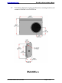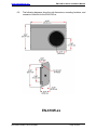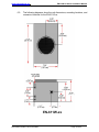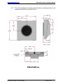
1
Installation Manual
EN-6xxW-xx Series
Woofer/Subwoofer Enclosure
Document # 540027
a DeCrane Aircraft Company
7300 Industry Drive, North Little Rock, AR 72117
Phone: 501-955-2929 Fax: 501-955-2988
www.audiointl.com
Audio International, Inc.
EN-6xxW-xx Series Installation Manual
Document Revision History
Rev. Level
IR
A
Date
04/1998
01/1999
B
03/2004
Description
Initial Release
Update to include all drawings to EN-600W series
Format Update, added photos, updated outline
drawings, added metric units to reference drawings.
Reference Documents
Document #
521441 Rev IR
521916 Rev IR
521917 Rev IR
521918 Rev IR
521882 Rev A
521908 Rev IR
521909 Rev IR
521910 Rev IR
521919 Rev IR
521920 Rev IR1
520954 Rev IR1
522148 Rev IR
520757 Rev IR
Description
EN-600W-xx Speaker
Outline drawing, EN-601W-xx
Outline drawing, EN-602W-xx
Outline drawing, EN-604W-xx
Outline Drawing EN-607W-x, -xx
Outline drawing, EN-608W-xx
Outline drawing, EN-609W-xx
Outline drawing, EN-610W-x
Outline drawing, EN-611W-x
Outline drawing, EN-612W-x
Speaker Enclosure EN-620W-xx
Outline drawing, EN-621W-x
Sub-Woofer, EN-646W-xx
Service Bulletin List
Service
Bulletin #
Subject
Manual
Revision
Revision
Date
Table of Illustrations
Section #
Description
Page #
2.2
Block Diagram
4
6.0
Reference Drawings
11-24
PROPRIETARY INFORMATION NOTICE: Despite any other copyright notice, this document
and information disclosed herein contains confidential, proprietary designs owned by Audio
International, Inc. Neither this document nor the data contained herein shall be reproduced,
used, or disclosed to anyone without the written authorization of Audio International, Inc.
Document # 540027, Rev B, 03/2004
Page 1 of 23
Audio International, Inc.
EN-6xxW-xx Series Installation Manual
Table of Contents
1.1
1.2
1.3
Description
General Information . . . . . . . . . . . . . . . . . . . . . . . . . . . . .
Introduction . . . . . . . . . . . . . . . . . . . . . . . . . . . . . . . . . . . . .
Purpose of the Equipment . . . . . . . . . . . . . . . . . . . . . . . . . .
Optional Equipment . . . . . . . . . . . . . . . . . . . . . . . . . . . . . . .
Page
3
3
3
4
2.1
2.2
Application . . . . . . . . . . . . . . . . . . . . . . . . . . . . . . . . . . . . .
Introduction . . . . . . . . . . . . . . . . . . . . . . . . . . . . . . . . . . . . .
Block Diagram - Typical Application. . . . . . . . . . . . . . . . . . .
4
4
4
3.1
3.2
3.3
3.4
3.5
3.6
3.7
3.8
3.9
Installation . . . . . . . . . . . . . . . . . . . . . . . . . . . . . . . . . . . . .
Prior to Installation . . . . . . . . . . . . . . . . . . . . . . . . . . . . . . . .
Unpacking and Inspection . . . . . . . . . . . . . . . . . . . . . . . . . .
Cautions & Warnings . . . . . . . . . . . . . . . . . . . . . . . . . . . . .
Wiring Requirements . . . . . . . . . . . . . . . . . . . . . . . . . . . . . .
Physical Characteristics . . . . . . . . . . . . . . . . . . . . . . . . . .
Electrical Characteristics . . . . . . . . . . . . . . . . . . . . . . . . . .
Mating Connector Information . . . . . . . . . . . . . . . . . . . . . . .
Pinout Assignments and Descriptions . . . . . . . . . . . . . . . . .
Post Installation Test . . . . . . . . . . . . . . . . . . . . . . . . . . . . . .
5
5
5
5
6
6
7
7
7
7
4.1
4.2
4.3
Troubleshooting. . . . . . . . . . . . . . . . . . . . . . . . . . . . . . . . .
Introduction . . . . . . . . . . . . . . . . . . . . . . . . . . . . . . . . . . . . .
General Troubleshooting Procedures . . . . . . . . . . . .. . . . .
Troubleshooting Chart . . . . . . . . . . . . . . . . . . . . . . . . . . . . .
8
8
8
9
5.0
Specifications . . . . . . . . . . . . . . . . . . . . . . . . . . . . . . . . . .
10
6.0
Reference Drawings . . . . . . . . . . . . . . . . . . . . . . . . . . . . .
11
Section
1.0
2.0
3.0
4.0
Document # 540027, Rev B, 03/2004
Page 2 of 23
Audio International, Inc.
EN-6xxW-xx Series Installation Manual
EN-6xxW-xx Series
Woofer/Subwoofer Enclosure
1.0
General Information
1.1
Introduction
1.1.1 This manual contains information for the proper installation of Audio
International’s (AI) Woofer/Subwoofer Enclosures, Model Numbers:
EN-600W-xx
EN-601W-xx
EN-602W-xx
EN-604W-xx
EN-607W-xx
EN-608W-xx
EN-609W-xx
EN-610W-xx
EN-611W-xx
EN-612W-xx
EN-620W-xx
EN-621W-xx
EN-646W-xx
Note that the EN-650W-01-x has its own separate Installation
manual, number 540246.
1.1.2 Information contained within this publication includes relative
physical, mechanical, and electrical characteristics. Also included
within this publication of the units. The “-xx” in the product model
number designates the speaker resistance and connector type.
See Section 3.6 for a breakdown of drivers and power ratings of
individual subwoofers.
1.1.3 These speaker enclosures are built to rugged aircraft standards
and are easily incorporated into new or existing systems. Features
include lightweight construction, integral mounting hardware, and
the latest in speaker technology.
1.2
Purpose of the Equipment
The EN-6xxW-xx Series are high quality speakers that feature durable,
lightweight aluminum enclosures with solid welded seams and acoustic
damping for clean sound with no “buzz” or vibration. Specialized acoustic
engineering packs maximum performance into the most compact
enclosures possible. All woofer / subwoofer enclosures include grills with
optional crossovers available.
Document # 540027, Rev B, 03/2004
Page 3 of 23
Audio International, Inc.
1.3
EN-6xxW-xx Series Installation Manual
Optional Equipment
Audio International, Inc. offers a comprehensive family of Cabin Control
Modules for PC interface. These modules provide convenient solutions
for a variety of frequently encountered interfacing needs or special
requirements and are an important part of AI’s “building block” system for
configuring total cabin management.
Contact your AI representative for details.
2.0
Application
2.1
Introduction
The EN-6xxW-xx Series speaker enclosures incorporate the latest in
subwoofer design technology. Solid welded seams and acoustic damping
are provided for clean sound with no “buzz” or vibration. Specialized
acoustic engineering packs maximum performance into the most compact
enclosure possible. Power ranges from 60 to 100 WRMS, depending on
the unit selected; see Section 3.6 for details. All models except for the
EN-646W-xx have options of either 4 or 8 Ω impedance (EN-646W-xx has
4 Ω impedance). A connector or pigtail with connector option is available.
2.2
Block Diagram -Typical Application
Document # 540027, Rev B, 03/2004
Page 4 of 23
Audio International, Inc.
3.0
EN-6xxW-xx Series Installation Manual
Installation
3.1
Prior to Installation
The EN-6xxW-xx Series speakers are simple modules to install. Prior to
installation the following items should be considered:
3.1.1 During the design and layout of the aircraft cabin, careful
consideration of the location of this and all other audio/video
modules is necessary. Some of the items to consider include:
•
•
•
•
•
•
Space
Proximity to other devices (i.e. source equipment)
Environmental conditions (temperature, humidity, etc.)
Location of other aircraft systems (i.e. oxygen delivery)
Access for service repair (if applicable)
Convenience for user interface (if applicable)
3.1.2 The EN-6xxW-xx Series speakers shall be installed to conform to
the standards designated by the customer, installing agency, and
existing conditions as to the unit location and type of installation.
3.2
Unpacking and Inspection
3.2.1 Carefully open the packaging and remove the speaker. Verify that
all components have been included in the package per the packing
list. Inspect the unit for shipping damage.
3.2.2 If damage has occurred during shipping, a claim should be filed
with Audio International WITHIN 24 hours and a Return Request
Authorization Number shall be obtained from AI. Refer to the
front cover of this manual for address and telephone number of
Audio International, Inc.
Repackage the unit in its original
packaging materials and return it to AI following instructions given
by the AI representative. If no return is necessary, retain the
packing list and the packing materials for storage.
3.3
Cautions and Warnings
3.3.1 It is important to do a pin-to-pin power and ground check on all
connectors. Ensure that Audio Input + and Audio Input - are
applied only where specified. Damage to the unit may result if
power or ground is applied to the wrong points.
3.3.2 DO NOT remove any factory-installed screws.
unit(s) may result and void any warranties.
Document # 540027, Rev B, 03/2004
Damage to the
Page 5 of 23
Audio International, Inc.
EN-6xxW-xx Series Installation Manual
3.3.3 DO NOT install near heat sources such as direct sunlight, warm air
exhausts, or heaters.
3.3.4 No scheduled maintenance is required to ensure continued
airworthiness.
3.3.5 ESD (Electro Static Discharge) guidelines shall be followed.
3.4
Wiring Requirements
3.4.1 The installing agency shall supply and fabricate all external cables
and connectors. Length and routing of external cables should be
carefully planned before attempting installation of the equipment.
Allow adequate space for installation of cable and connectors.
3.4.2 Ensure that all signal wires are 18 AWG minimum (16 AWG
recommended).
3.5
Physical Characteristics
3.5.1 The speaker shall be located away from heat sources, magnetic
fields, direct sunlight, and areas with excessive dust. The unit shall
NOT be mounted to the skin of the aircraft.
3.5.2 Refer to 6.0 for unit dimensions and mounting hole sizes.
3.5.3 The unit shall be rigidly mounted to its location using the
appropriate fastening hardware supplied by the installing agency.
3.5.4 When mounting the unit to the aircraft’s frame, allow sufficient
space for mating connectors.
3.5.5 Do not remove the speaker from the enclosure; the speaker is
sealed in place to provide optimum performance.
3.5.6 Audio International recommends not restricting airflow in front of the
enclosure.
Coverings or grills not specifically designed for
loudspeaker performance may cause unacceptable loss of sound
quality.
Document # 540027, Rev B, 03/2004
Page 6 of 23
Audio International, Inc.
3.6
EN-6xxW-xx Series Installation Manual
Electrical Characteristics
Model
EN-600W-xx
EN-601W-xx
EN-602W-xx
EN-604W-xx
EN-607W-xx
EN-608W-xx
EN-609W-xx
EN-610W-xx
EN-611W-xx
EN-612W-xx
EN-620W-xx
EN-621W-xx
EN-622W-xx
EN-646W-xx
3.7
Drivers
AI-612 6.5"
AI-620 6.5"
AI-612 6.5"
AI-612 6.5"
AI-620 6.5"
AI-612 6.5"
AI-612 6.5"
AI-612 6.5"
AI-620 6.5"
AI-612 6.5"
AI-612 6.5"
Infinity
Infinity
AI-612 6.5"
Power
60 WRMS
100 WRMS
60 WRMS
60 WRMS
100 WRMS
60 WRMS
60 WRMS
60 WRMS
100 WRMS
60 WRMS
60 WRMS
100 WRMS
100 WRMS
100 WRMS
Impedance
4 or 8 Ω
4 or 8 Ω
4 or 8 Ω
4 or 8 Ω
4 or 8 Ω
4 or 8 Ω
4 or 8 Ω
4 or 8 Ω
4 or 8 Ω
4 or 8 Ω
4 or 8 Ω
4 or 8 Ω
4 or 8 Ω
4Ω
Mating Connector Information
Model Number
-4 or -8
-4P or -8P
(12" Pigtail)
Manufacturer
ITT Cannon
AMP
Mating Connector
MS3122E10-6S
1-480699-0 Receptacle
350689-1 Socket
The enclosures utilize one of two connectors; a two-pin Amp on 12" Pigtail
or ITT Cannon connector. Refer to individual options available upon
purchase. Exception: EN-646W-xx utilizes MS3476L only.
3.8
Pinout Assignment and Descriptions
EN-6xxW-xx Series
Pin #
1
2
3.9
Description
Audio Input +
Audio Input -
Post-Installation Test
Verify all connections to the unit(s) are making contact. With the aircraft
power ON, test the speaker’s performance with any properly connected
audio unit.
Document # 540027, Rev B, 03/2004
Page 7 of 23
Audio International, Inc.
4.0
EN-6xxW-xx Series Installation Manual
Troubleshooting
4.1
Introduction
Most functional problems will be detected during the post installation test;
refer to Post-Installation Test, Section 3.9. Once the unit has passed
these tests, it can be functional for many years of service. Most problems
with sound quality are not due to subwoofer performance, but instead are
caused by source equipment or faulty audio material. Always check
source equipment and audio material as well as the speaker in question.
NO scheduled maintenance is required to ensure continued airworthiness.
EN-6xxW-xx has no customer-serviceable parts. If the unit does not work
properly, it should be removed and replaced. Contact Audio International
for details.
4.2
General Troubleshooting Procedures
•
Recheck all connections to the unit for security. Check all harness
runs for possible pinching and all pinouts for application accuracy.
The following troubleshooting procedures apply to the equipment
supplying audio to the subwoofers and not to the subwoofers
themselves.
•
•
•
Reset by removing power from the unit for at least one (1) minute and
reapply power.
To verify power to the unit, recheck +28 VDC power is applied to the
proper pins on the unit. Use a voltmeter to verify correct level.
To check data bus integrity, utilizing a voltmeter, oscilloscope, or other
voltage instrument, verify proper input voltage on the data bus pins.
Typical measurements with no device(s) on bus transmitting are as
follows:
A-to-Ground : 4.0 to 4.5 VDC
B-to-Ground : 0.1 to 1.0 VDC
If any device is transmitting (i.e., holding bus active), then these typical
measurements would be reversed for the A-to-Ground and B-toGround measurements. This troubleshooting tool can help indicate a
data bus lockup. If this occurs, remove the data bus from all other
equipment one piece at a time. As each is removed, check the bus
status to see if it is now functioning properly. Once you have removed
the piece or pieces of offending equipment, disconnect power and then
reconnect everything but the suspect component, reapply power and
test the functionality of the unit.
Document # 540027, Rev B, 03/2004
Page 8 of 23
Audio International, Inc.
•
4.3
EN-6xxW-xx Series Installation Manual
The RS-485 data bus is a bi-directional bus that does not have a ‘bus
controller’. The bus uses a differential digital signal that will transmit
only when commands are entered via switch selection or other system
synchronizing commands. The “A” leg of the bus is HI and the “B” leg
LOW.
Troubleshooting Chart
Problem
Speaker
produces no
sound
Speaker does not
produce highquality sound
Document # 540027, Rev B, 03/2004
Possible Cause
Unit improperly
installed
•
Solution
Check all connections.
Replace connectors if
required. Verify that any
source equipment is
installed correctly.
Source equipment
not loaded with
audio material
•
Load source equipment with
material.
Source equipment
not turned on
•
Turn on source equipment.
Using dirty or
damaged audio
material
•
Replace with clean,
undamaged material.
Interference from
outside source
•
Run wire away from
interfering sources.
System not properly
aligned
•
Correctly realign system.
Page 9 of 23
Audio International, Inc.
5.0
EN-6xxW-xx Series Installation Manual
Specifications
Physical Specifications
Model
EN-600W-xx
EN-601W-xx
EN-602W-xx
EN-604W-xx
EN-607W-xx
EN-608W-xx
EN-609W-xx
EN-610W-xx
EN-611W-xx
EN-612W-xx
EN-620W-xx
EN-621W-xx
EN-646W-xx
Housing
Sealed
Aluminum
Sealed
Aluminum
Sealed
Aluminum
Sealed
Aluminum
Sealed
Aluminum
Sealed
Aluminum
Sealed
Aluminum
Sealed
Aluminum
Sealed
Aluminum
Sealed
Aluminum
Sealed
Aluminum
Sealed
Aluminum
Sealed
Aluminum
Document # 540027, Rev B, 03/2004
Length
14.0"
(36 cm)
12.0 "
(30.5 cm)
16.0"
(40.6 cm)
12.0"
(30.5 cm)
16.0"
(40.6 cm)
10.0"
(25.4 cm)
14.0"
(36 cm)
14.0"
(36 cm)
12.0"
(30.5 cm)
10.0"
(25.4 cm)
12.0"
(30.5 cm)
16.0"
(40.6 cm)
14.0"
(36 cm)
Width
7.17"
(18.2 cm)
7.5"
(19 cm)
7.5"
(19 cm)
10.0"
(25.4 cm)
7.5"
(19 cm)
7.0"
(18 cm)
9.83"
(25 cm)
9.83"
(25 cm)
7.5"
(19 cm)
10.0"
(25.4 cm)
7.0"
(18 cm)
7.5"
(19 cm)
7.17"
(18.2 cm)
Height
4.37"
(11.1 cm)
7.5"
(19 cm)
3.5"
(8.9 cm)
4.0"
(10 cm)
4.32"
(11 cm)
3.5"
(8.9 cm)
3.75"
(9.52 cm)
3.75"
(9.52 cm)
6.5"
(17 cm)
3.75"
(9.52 cm)
3.5"
(8.9 cm)
4.35"
(11 cm)
4.37"
(11.1 cm)
Weight
5.7 lb
(2.6 kg)
9.1 lb
(4.1 kg)
5.8 lb
(2.6 kg)
5.8 lb
(2.6 kg)
8.5 lb
(3.9 kg)
5.9 lb
(2.7 kg)
6.3 lb
(2.9 kg)
6.3 lb
(2.9 kg)
8.5 lb
(3.9 kg)
5.8 lb
(2.6 kg)
5.7 lb
(2.6 kg)
4.75 lb
(2.15 kg)
5.7 lb
(2.6 kg)
Page 10 of 23
Audio International, Inc.
6.0
EN-6xxW-xx Series Installation Manual
Reference Drawings
6.1
The following diagrams show the unit dimensions, mounting locations, and
connector locations for the EN-600W-xx.
EN-600W-xx
Document # 540027, Rev B, 03/2004
Page 11 of 23
Audio International, Inc.
6.2
EN-6xxW-xx Series Installation Manual
The following diagrams show the unit dimensions, mounting locations, and
connector locations for the EN-601W-xx.
EN-601W-xx
Document # 540027, Rev B, 03/2004
Page 12 of 23
Audio International, Inc.
6.3
EN-6xxW-xx Series Installation Manual
The following diagrams show the unit dimensions, mounting locations, and
connector locations for the EN-602W-xx.
EN-602W-xx
Document # 540027, Rev B, 03/2004
Page 13 of 23
Audio International, Inc.
6.4
EN-6xxW-xx Series Installation Manual
The following diagrams show the unit dimensions, mounting locations, and
connector locations for the EN-604W-xx.
EN-604W-xx
Document # 540027, Rev B, 03/2004
Page 14 of 23
Audio International, Inc.
6.5
EN-6xxW-xx Series Installation Manual
The following diagrams show the unit dimensions, mounting locations, and
connector locations for the EN-607W-xx.
EN-607W-xx
Document # 540027, Rev B, 03/2004
Page 15 of 23
Audio International, Inc.
6.6
EN-6xxW-xx Series Installation Manual
The following diagrams show the unit dimensions, mounting locations, and
connector locations for the EN-608W-xx.
EN-608W-xx
Document # 540027, Rev B, 03/2004
Page 16 of 23
Audio International, Inc.
6.7
EN-6xxW-xx Series Installation Manual
The following diagrams show the unit dimensions, mounting locations, and
connector locations for the EN-609W-xx.
EN-609W-xx
Document # 540027, Rev B, 03/2004
Page 17 of 23
Audio International, Inc.
6.8
EN-6xxW-xx Series Installation Manual
The following diagrams show the unit dimensions, mounting locations, and
connector locations for the EN-610W-xx.
EN-610W-xx
Document # 540027, Rev B, 03/2004
Page 18 of 23
Audio International, Inc.
6.9
EN-6xxW-xx Series Installation Manual
The following diagrams show the unit dimensions, mounting locations, and
connector locations for the EN-611W-xx.
EN-611W-xx
Document # 540027, Rev B, 03/2004
Page 19 of 23
Audio International, Inc.
6.10
EN-6xxW-xx Series Installation Manual
The following diagrams show the unit dimensions, mounting locations, and
connector locations for the EN-612W-xx.
EN-612W-xx
Document # 540027, Rev B, 03/2004
Page 20 of 23
Audio International, Inc.
6.11
EN-6xxW-xx Series Installation Manual
The following diagrams show the unit dimensions, mounting locations, and
connector locations for the EN-620W-xx.
EN-620W-xx
Document # 540027, Rev B, 03/2004
Page 21 of 23
Audio International, Inc.
6.12
EN-6xxW-xx Series Installation Manual
The following diagrams show the unit dimensions, mounting locations, and
connector locations for the EN-621W-xx.
EN-621W-xx
Document # 540027, Rev B, 03/2004
Page 22 of 23
Audio International, Inc.
6.13
EN-6xxW-xx Series Installation Manual
The following diagrams show the unit dimensions, mounting locations, and
connector locations for the EN-646W-xx.
EN-646W-xx
Document # 540027, Rev B, 03/2004
Page 23 of 23