1
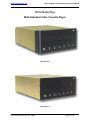
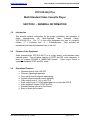
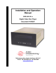
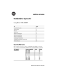
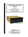
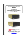
Installation and Operation
Manual
VCP-010-06(-07)-x
Multi-Standard Video Cassette Player
Document # 540236
VCP-010-06-x
VCP-010-07-x
a DeCrane Aircraft Company
7300 Industry Drive, North Little Rock, AR 72117
Phone: 501-955-2929 Fax: 501-955-2988
www.audiointl.com
Audio International, Inc.
VCP-010-06(-07)-x Installation & Operation Manual
Document Revision History
Rev. Level
Date
Description
IR
11/2002
Initial Release
Reference Documents
Document #
Description
523772 Rev A4
VCP-010-06-x Outline Drawing
523797 Rev IR1
VCP-010-07-x Outline Drawing
Service Bulletin List
Service
Bulletin #
Manual
Revision
Subject
Revision
Date
Table of Illustrations
Section #
Subsection #
Description
Page #
I
6.2
Typical Application
6-7
II
9.1
Reference Drawings (VCP-010-06-x)
15-16
II
9.2
Reference Drawings (VCP-010-07-x)
17-18
III
1.0
Front Panel
20
PROPRIETARY INFORMATION NOTICE: Despite any other copyright notice, this document
and information disclosed herein contains confidential, proprietary designs owned by Audio
International, Inc. Neither this document nor the data contained herein shall be reproduced,
used, or disclosed to anyone without the written authorization of Audio International, Inc
Document # 540236, Rev IR, 11/2002
Page 1 of 21
Audio International, Inc.
VCP-010-06(-07)-x Installation & Operation Manual
Table of Contents
Section
Description
Page
1.0
2.0
3.0
4.0
5.0
6.0
GENERAL INFORMATION…………………………………...
Introduction……………………………………………………...
Purpose of the Equipment…………………………………….
Operational Features…………………………………………..
Optional Equipment…………………………………………….
Technical Specifications……………………………………….
Application………………………………………………………
4
4
4
4
5
5
5
1.0
2.0
3.0
4.0
5.0
6.0
7.0
8.0
9.0
INSTALLATION………………………………………………..
Prior to Installation……………………………………………..
Unpacking and Inspection……………………………………..
Cautions & Warnings…………………………………………..
Wiring Requirements…………………………………………..
Physical Characteristics……………………………………….
Electrical Characteristics………………………………………
Post-Installation Test…………………………………………..
Troubleshooting………………………………………………...
Reference Drawings……………………………………………
8
8
8
9
10
11
11
13
13
15
1.0
2.0
3.0
OPERATION……………………………………………………
General Information……………………………………………
To Load a Videocassette Tape into Tape Slot……………..
Front Panel Button Functions…………………………………
19
19
20
21
I
II
III
Document # 540236, Rev IR, 11/2002
Page 2 of 21
Audio International, Inc.
VCP-010-06(-07)-x Installation & Operation Manual
VCP-010-06(-07)-x
Multi-Standard Video Cassette Player
VCP-010-06-x
VCP-010-07-x
Document # 540236, Rev IR, 11/2002
Page 3 of 21
Audio International, Inc.
VCP-010-06(-07)-x Installation & Operation Manual
VCP-010-06(-07)-x
Multi-Standard Video Cassette Player
SECTION I – GENERAL INFORMATION
1.0
Introduction
This manual contains information for the proper installation and operation of
Audio
International’s
(AI)
Multi-Standard
Video
Cassette
Player,
VCP-010-06(-07)-x. The “-x” in the suffix designates the type of connector
utilized; “-1” = Positronic and “-2” = D-Subminiature. Also included are
mechanical and electrical characteristics of the unit.
2.0
Purpose of the Equipment
Audio International’s VCP-010-06(-07)-x is a high quality, multi-standard video
cassette player. This unit plays versions of NTSC and PAL video cassettes. It
does not support SECAM or MESECAM formats. Video output format is
selectable between NTSC and PAL mode.
3.0
Operational Features
Operates directly from +28 VDC
Compact, lightweight package
G Front panel controls w/green backlighting
G Optional infrared remote control capability
G Video output level of 1 V(p-p) into 75 Ω
G Audio output level of 2 VRMS adjustable into not less than 600 Ω
G Video playback formats: NTSC and PAL
G Standard plating options for front bezel
G Easy to mount and connect
G
G
Document # 540236, Rev IR, 11/2002
Page 4 of 21
Audio International, Inc.
4.0
VCP-010-06(-07)-x Installation & Operation Manual
Optional Equipment
AI source equipment can be optionally controlled by infrared remote
(AI-RCx-17xxxx). Playback options with this remote include visual search,
pause, play, stop, fast forward, rewind, eject, and format.
Contact your AI representative for details.
5.0
Technical Specifications
Physical Specifications-VCP-010-06-x
Housing
Weight
Dimensions
(l x w x h)
Aluminum
8.80 lb / 3.99 kg
12.12" x 10.35" x 4.25"
30.78 cm x 26.9 cm x 10.8 cm
Physical Specifications-VCP-010-07-x
Housing
Weight
Dimensions
(l x w x h)
6.0
Aluminum
8.75 lb / 3.97 kg
13.6" x 10.4" x 4.3"
34.5 cm x 26.4 cm x 11 cm
Application
6.1
Introduction
6.1.1 The VCP-010-06(-07)-x is a high quality, multi-standard video
cassette player. This unit plays versions of NTSC and PAL
videocassettes. The video output format is selectable between
NTSC and PAL mode.
6.1.2 The VCP-010-06(-07)-x will accept a +5 VDC infrared digital input
and AI’s proprietary RS-485 two-wire serial data bus input.
Document # 540236, Rev IR, 11/2002
Page 5 of 21
Audio International, Inc.
VCP-010-06(-07)-x Installation & Operation Manual
6.1.3 The video output connector (BNC1) allows for connection of the
VCP to the video source selector. Since the video source does not
have audio switching, it will provide video output only. Separate
audio outputs are provided.
6.1.4 If power is interrupted (>250 msec) while a cassette is in the video
player, the player will shut down and the cassette must be ejected
and reinserted into the VCP to restart playback.
6.1.5 The VCP powers up to an output of NTSC. Press the FORMAT
button on the front of the player to change the output standard
between NTSC and PAL.
6.2
Typical Application
6.2.1 This system is fully compatible with Audio International’s proprietary
RS-485 digital data bus system. It can be configured for IR remote
control utilizing AI’s remote control unit AI-RCx-17xxxx and
IFR-485.
Document # 540236, Rev IR, 11/2002
Page 6 of 21
Audio International, Inc.
VCP-010-06(-07)-x Installation & Operation Manual
6.2.2 The unit can also be configured for IR remote control utilizing AI’s
remote control unit AI-RCx-17xxxx and IFR-9A. This following
configuration utilizes a +5 VDC digital logic level for activation of
infrared commands. Connection to multiple IFR-9A units utilizing
the +5 VDC digital logic level connection requires an external
Schottkey diode at each IFR-9A unit. This will prevent signal
loading. Contact AI for details.
6.2.3 The unit can also be configured for Touch Screen or remote panel
control (i.e. entertainment control panels). The panels are on AI’s
proprietary RS-485 digital data bus system and configured to
control the operational features of the VCP-010-06(-07)-x.
Document # 540236, Rev IR, 11/2002
Page 7 of 21
Audio International, Inc.
VCP-010-06(-07)-x Installation & Operation Manual
SECTION II - INSTALLATION
1.0
Prior to Installation
1.1
During the design and layout of the aircraft cabin, careful consideration of
the location of this and all other audio/visual modules is necessary. Some
of the items to be considered include:
•
•
•
•
•
•
•
•
2.0
Space
Proximity to other devices (i.e. source equipment)
Available power supply
Length of cable runs
Environmental conditions (temperature, humidity, etc.)
Location of other aircraft systems (i.e. oxygen delivery)
Access for service repair (if applicable)
Convenience for user interface
1.2
The VCP-010-06(-07)-x shall be installed to conform to the standards
designated by the customer, installing agency, and existing conditions as
to the unit location and type of installation.
1.3
Mounting screws are required to secure the unit. Refer to Section II, 9.0
for mounting hole diameters and configurations.
1.4
All headphone amplifiers and line level amplifiers shall be located no more
than three (3) feet away from the VCP-010-06(-07)-x. Long low-level
audio runs may introduce noise into the audio signal.
1.5
The VCP-010-06(-07)-x must be mounted in a horizontal position (not on
its side or back).
1.6
Temperature consideration of the installation area is important. Operating
temperature range for the unit shall be between -15° and +55° Celsius.
1.7
Avoid installing the unit where it will be exposed to excessive heat,
moisture, splashing liquids, dusty areas, or direct sunlight.
Unpacking and Inspection
2.1
Carefully open the packaging and remove the VCP-010-06(-07)-x. Verify
that all components have been included in the package per the packing
list. Inspect the unit for shipping damage.
Document # 540236, Rev IR, 11/2002
Page 8 of 21
Audio International, Inc.
2.2
3.0
VCP-010-06(-07)-x Installation & Operation Manual
If damage has occurred during shipping, a claim should be filed with Audio
International WITHIN 24 hours and a Return Request Authorization
Number shall be obtained from AI. Refer to the front cover of this manual
for address and telephone number of Audio International, Inc. Repackage
the unit in its original packaging materials and return it to AI following
instructions given by the AI representative. If no return is necessary,
retain the packing list and the packing materials for storage.
Cautions & Warnings
3.1
It is important to do a pin-to-pin power and ground check on all
connectors. Ensure power and ground are applied only where specified.
Damage may result if power or ground is applied to the wrong points.
3.2
DO NOT connect or disconnect the unit while power is applied.
3.3
DO NOT remove any factory-installed screws. Damage to the unit may
result and void any warranties.
3.4
DO NOT attempt to open the case. Refer servicing to qualified personnel.
3.5
DO NOT place foreign objects into openings. Contact with foreign objects
may result in dangerous voltage or electric chock.
3.6
DO NOT place unit near hot air ducts or other heat sources.
3.7
DO NOT use this unit other than for its intended purpose. Doing so might
lead to electric shock, injury, or damage to the equipment.
3.8
DO NOT use near water, moisture, or volatile sprays. Do not use any type
of solvent when cleaning the unit; surface damage may occur.
3.9
DO NOT leave cassette tapes loaded in the unit with no power applied.
3.10
NO scheduled maintenance is required to ensure airworthiness.
3.11
Screw depth should NOT exceed 0.25" on front holes.
3.12
ESD (Electro Static Discharge) guidelines shall be followed.
Document # 540236, Rev IR, 11/2002
Page 9 of 21
Audio International, Inc.
4.0
VCP-010-06(-07)-x Installation & Operation Manual
Wiring Requirements
4.1
Introduction
The installing agency shall supply and fabricate all external cables. The
length and routing of external cables should be carefully studied and
planned before attempting installation of the equipment. Allow adequate
space for installation of cable and connectors. Avoid sharp bends and
placing cables near aircraft control cables. Maintain a minimum clearance
of three (3) inches from any control cable. If wiring is run parallel to
combustible fluid or oxygen lines, maintain a minimum separation of six
(6) inches between the lines.
4.2
Power Wires
All power and ground wires shall be 22 AWG, MINIMUM shielded twisted
pair with the shield properly bonded at one end only. Power ground wires
shall be bonded to electrically conductive chassis mounting point with
<1 Ω resistance or <50 Ω impedance. Twisted shielded cable shall be in
accordance with NEMA WC 27500 or equivalent.
4.3
Audio Wires
All audio connections require twisted, shielded cable with the cable shields
properly grounded at the source. Twisted shielded cable shall be in
accordance with NEMA WC 27500 or equivalent.
4.4
Video Wires
Composite video connections shall be shielded coaxial cable in
accordance with M17/94-RG179 or equivalent.
Document # 540236, Rev IR, 11/2002
Page 10 of 21
Audio International, Inc.
4.5
VCP-010-06(-07)-x Installation & Operation Manual
AI’s Proprietary RS-485 Data Bus
4.5.1 The VCP-010-06(-07)-x is designed to interface with other Audio
International equipment via AI’s proprietary RS-485 serial data bus.
The data bus shall be implemented using a twisted shielded pair
cable in accordance with NEMA WC 27500 or equivalent. The wire
size for the conductors in this cable shall be 22 AWG, MINIMUM.
The shield shall be connected as required. Shield terminations
shall be made as close to the connector pin as possible.
4.5.2 All modules on AI’s proprietary RS-485 data bus shall be connected
in a ‘daisy-chain’ configuration. AI’s proprietary RS-485 data bus
specification is available upon request.
5.0
6.0
Physical Characteristics
5.1
Refer to Section I, 5.0 for unit dimensions and Section II, 9.0 for
attachment points.
5.2
When mounting the unit, allow sufficient space for mating connectors.
5.3
DO NOT insert any screw more than 0.25" into the case. Mounting holes
on the unit provide multiple anchoring points. These threaded inserts do
not have physical stops. Care should be taken not to penetrate the outer
casing more than 0.25" with any screw. This could result in serious
damage to the video cassette player.
Electrical Characteristics
6.1
Electrical Specifications:
Electrical
Document # 540236, Rev IR, 11/2002
Power
Operating Voltage
Range
Data Bus Type
Audio Frequency
Response
Audio S/N
Video Output
Playback Format
Video Output
Video Heads
Infrared Signal Input
1A @ +28 VDC
+18 to +32 VDC
AI Proprietary RS-485
200 Hz to 8 kHz
>37 dB (NOMINAL)
1 V(p-p) into 75 Ω
PAL & NTSC (auto detect)
NTSC, PAL (selectable)
4
+5 VDC digital logic level
Page 11 of 21
Audio International, Inc.
VCP-010-06(-07)-x Installation & Operation Manual
6.2
The VCP-010-06(-07)-x utilizes one (1) 15-pin connector for electrical
connections. This connector provides power, left/right audio output, data
bus control, infrared input, and four (4) infrared strapping pins for alternate
configuration of infrared digital command codes. Utilizing these infrared
inputs, the VCP-010-06(-07)-x can be configured to accept up to four (4)
different sets of infrared codes or eight (8) separate RS-485 addresses.
This allows up to four (4) of the same devices when using infrared inputs
or eight (8) of the same devices when using the RS-485 data bus to be
used in the same system while maintaining independent control. Three
(3) strap pins are available to configure the infrared codes and RS-485
addressing.
Standard configuration requires no strap pins to be
connected. To change the code settings, connect one (1) of the strap pins
to the strap common.
6.3
Mating Connector Information
Model #
VCP-010-06(-07)-1
VCP-010-06(-07)-2
BNC1 Video Output
6.4
Mating Connector
RD15F10JVL0
DAMA-15S
D20418-2 Female Screwlock
AMPHENOL 31-7008 or equivalent
Pinout Assignment and Descriptions
Pin Configuration
VCP-010-06(-07)-x
Pin #
Description
1
+ 28 VDC, Power Input
2
Ground
3
R+ Audio Output
4
R- Audio Output
5
L+ Audio Output
6
L- Audio Output
7
Data Bus (A)
8
Data Bus (B)
9
Infrared Input +
10
Infrared Input 11
IR Strap 2
12
IR Strap 3
13
IR Strap 4
14
IR Strap Common
15
Reserved
Document # 540236, Rev IR, 11/2002
Page 12 of 21
Audio International, Inc.
7.0
8.0
VCP-010-06(-07)-x Installation & Operation Manual
Post-Installation Test
7.1
Verify +28 VDC power has been connected to the unit. The audio signal
output of the unit is generally connected to cabin speaker systems in
addition to headphone locations. Verify all connections before supplying
power to the unit.
7.2
Load the VCP-010-06(-07)-x with a videocassette tape. Use the front
panel controls or the hand-held remote control unit to select PLAY. Check
for a picture on the appropriate monitor. Verify that the audio can be
heard through the speaker and/or the headphone system.
7.3
Use the front panel controls (and the hand-held remote, if applicable) to
each of the functions; ensure that the unit rewinds, fast-forwards, stops,
pauses, and ejects as appropriate. See Section III, subsection 3.0 for
detailed descriptions of the units’ controls.
Troubleshooting
8.1
General Troubleshooting Procedures
•
•
•
•
•
•
•
Check that +28 VDC power is applied to the proper pins on the unit.
Use a voltmeter to verify correct level.
Reset the unit by removing power from it for at least one (1) minute
and then reapply power.
Make certain that the video cassette is clean. If dirty cassettes are
used, it may become necessary to clean the unit with a commercial
Video Head Cleaner.
Recheck all connections to the unit for security. Check all harness
runs for possible pinching. Recheck all pinouts for application
accuracy.
RS-485 data bus is a bi-directional bus without a “bus controller.” The
bus uses a differential digital signal that transmits only when
commands are entered via switch selection or other system
synchronizing commands. The “A” leg of the bus is HI and the “B” leg
LOW.
If the picture is unclear, too dark, or too light, press the FORMAT
button located on the VCP front panel to change video formats.
To check data bus integrity, utilizing a voltmeter, oscilloscope, or other
voltage instrument, verify proper input voltage on the data bus pins.
Typical measurements verifying proper conditions are:
A to Ground : 4.0 to 4.5 VDC
B to Ground : 0.1 to 0.2 VDC
Document # 540236, Rev IR, 11/2002
Page 13 of 21
Audio International, Inc.
8.2
VCP-010-06(-07)-x Installation & Operation Manual
Troubleshooting Chart
Problem
No power
Unclear picture
Possible Cause
Solution
Ø
Faulty wiring
•
Verify +28 VDC power and
audio/video input is present and
recheck connections
Ø
Circuit breaker not
‘ON’
•
Turn circuit breaker to ‘ON’
position
Ø
Video heads may
be dirty
•
Use a commercial head cleaner
•
Replace videocassette tape
Ø
Incorrect Format
•
Change Format
Ø
Cassette not
loaded
•
Load videocassette
Ø
Tape defective
•
Replace videocassette tape
Ø
Video connector
not operational
•
Reconnect or repair cable
Ø
Defective
videocassette
tape
•
Replace videocassette
Ø
Power/Audio
connector not
operational
•
Reconnect or repair cable
Buttons not
operating
Ø
Moisture may
have condensed
inside the unit
•
Allow unit to warm to room
temperature and moisture to
evaporate
Tape cannot be
inserted
Ø
Foreign object in
tape slot
•
Remove foreign object
Unit does not eject
Ø
EJECT button not
functioning
•
Verify +28 VDC power and check
connections
Video not present
Audio not present
Document # 540236, Rev IR, 11/2002
Page 14 of 21
Audio International, Inc.
9.0
VCP-010-06(-07)-x Installation & Operation Manual
Reference Drawings
9.1
The following diagrams show the unit dimensions, mounting locations, and
connector locations for the VCP-010-06-x.
Document # 540236, Rev IR, 11/2002
Page 15 of 21
Audio International, Inc.
Document # 540236, Rev IR, 11/2002
VCP-010-06(-07)-x Installation & Operation Manual
Page 16 of 21
Audio International, Inc.
9.2
VCP-010-06(-07)-x Installation & Operation Manual
The following diagrams show the unit dimensions, mounting locations, and
connector locations for the VCP-010-07-x.
Document # 540236, Rev IR, 11/2002
Page 17 of 21
Audio International, Inc.
Document # 540236, Rev IR, 11/2002
VCP-010-06(-07)-x Installation & Operation Manual
Page 18 of 21
Audio International, Inc.
VCP-010-06(-07)-x Installation & Operation Manual
SECTION III – OPERATION
1.0
General Information
1.1
The VCP-010-06(-07)-x can be operated via front panel ‘buttons’ or
optionally controlled by infrared remote or AI’s touch screen panel. Digital
codes allow the unit to interface with an infrared handheld remote via an
infrared receiver, IFR-9A or IFR-485.
1.2
Utilizing the infrared inputs, the VCP-010-06(-07)-x can be configured to
accept up to four (4) different sets of infrared codes or eight (8) separate
RS-485 addresses. This allows up to four (4) of the same devices when
using infrared inputs or eight (8) of the same devices when using the
RS-485 data bus to be used in the same system while maintaining
independent control. Three (3) strap pins are available to configure the
infrared codes and RS-485 addressing. Standard configuration requires
no strap pins to be connected. To change the code settings, connect one
(1) of the strap pins to the strap common.
1.3
Playback options with front ‘button’ controls, remote, or touch screen
controls include stop, eject, fast-forward, rewind, and pause.
1.4
When the VCP-010-06(-07)-x reaches the end of the videocassette, the
unit will automatically enter rewind mode. As a safety precaution, the
VCP-010-06(-07)-x has been designed so that it will not automatically
eject when the tape has been fully rewound. The EJECT button on the
front panel must be pressed to unload the videocassette tape.
Document # 540236, Rev IR, 11/2002
Page 19 of 21
Audio International, Inc.
VCP-010-06(-07)-x Installation & Operation Manual
ILLUSTRATION OF FRONT PANEL BUTTONS
(Note that the VCP-010-07-x cover bezel is used for reference only; the button
configuration is the same on all VCP-010-06(-07)-x models)
2.0
To Load a Videocassette Tape into the Tape Slot
2.1
Gently insert a videocassette tape into the cassette tape slot. Apply slight
forward pressure to the side edge of the tape. The VCP-010-06(-07)-x will
gently ‘pull’ the tape into the player.
Playback begins playing
automatically when the videocassette is inserted into the slot.
2.2
If the videocassette is inserted incorrectly, the loading system will not
function. Do not force the tape into the unit. See section 8.2,
Troubleshooting, if difficulties arise in getting the VCP to accept a
videocassette.
Document # 540236, Rev IR, 11/2002
Page 20 of 21
Audio International, Inc.
3.0
VCP-010-06(-07)-x Installation & Operation Manual
Front Panel Button Functions
3.1
Format Button – Press the FORMAT button to switch between PAL
and NTSC output modes.
3.2
Stop Button – Press the STOP button to stop videocassette tape
playback.
3.3
Rewind Button – While the tape is playing, press the REW button
and the tape will reverse direction until the STOP or PLAY button is
pressed. This allows for a visual search through the preceding
scenes on the videocassette. Audio will not be present during this
“reverse search” mode. Pressing the REW again during reverse
search will accelerate the process. To rewind the videocassette,
press the STOP button and then press the REW button. (The
picture cannot be viewed in this mode.) Press the STOP button at
any time during rewind to stop the REW function. Press PLAY to
resume playback of the videocassette tape.
3.4
Play Button – Press the PLAY button to begin videocassette tape
viewing. Pressing PLAY twice in succession activates doublespeed play.
3.5
Fast Forward Button – While the tape is playing, press the
FF button and the tape will fast-forward search until the STOP or
PLAY button is pressed. Audio will not be present during this
search mode. Pressing the FF button again will accelerate the fastforwarding process. For maximum fast-forward, press the STOP
button and then press the FF button. (The picture cannot be
viewed in this mode.) Press the STOP button at any time during
fast-forward to stop the FF function. Press PLAY to resume
playback of the videocassette tape.
3.6
Pause Button – Press the PAUSE button during playback to
temporarily stop the playback of the videocassette tape. Video will
remain visible. Pressing PAUSE again will advance the movie one
frame forward. To return to normal viewing, press the PLAY button.
3.7
Eject Button – Press the EJECT button at any time to eject a
videocassette from the unit. The tape will stop and eject regardless
of current function.
Document # 540236, Rev IR, 11/2002
Page 21 of 21