1
APPLIED PCs
by Fred Eady
Simple Data Display
Driving LCDs with Microchip and Atmel Micros
Thinking about incorporating an LCD in your next design? It isn’t too difficult, especially if all
you’re looking to do is display your data as a set of numeric digits. Follow along as Fred
shows you how Microchip and Atmel can help you drive a simple data display.
Y
ears ago, I wore a Seiko watch
that was both analog and digital. The
watch had a standard watch face with
all of the normal moving hands plus a
tiny LCD that displayed the date and
did double-duty as a stopwatch. At the
time, the good old LED-based watches
had been replaced by the newer and
fancier LCD watches. By wearing my
Seiko, I was opting for the classic look
with the new technology feel.
The LCD-in-watch trend is still
alive and well. There are numerous
watches on the market that are LCDenabled and tout a boatload of features. I remember when calculator
watches were big. These days, calculator watches are a no-brainer. Now you
can buy a watch that graphs the phases of the moon and tidal activity in
addition to keeping the time and noting when the sun sets and rises.
There’s even a touch-enabled, LCDfaced watch out there that runs Linux!
This month’s column is not about
fancy watches; it’s all about LCDs.
My office telephone, cell phone, and
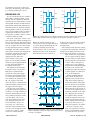
Segment line 1
SEG1
Engergized
LCD segment
SEG0
Segment line 0
Non-engergized
LCD segment
Common terminal 0
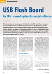
Figure 1—An LCD operating in Static Duty mode is much
like its LED counterpart, because a different segment
driver addresses each display segment individually.
58
Issue 159
October 2003
pager have one. My Microchip PRO
you need to see your LCD module’s
MATE II device programmer has one.
dots in the dark, you can buy an LCD
module with an integral backlight.
My VOM has one. My SMT rework
The LCD module is a good choice if
machine has one. Even my atomic
you want to easily display multiline
clock (that locks into WWV only
text messages; however, the cost rises
when it feels like it) has one.
considerably as you add extra lines of
Have you ever thought about why
text to the display.
LCDs are so prevalent? The answer is
It doesn’t matter if you use LEDs or
simple: they’re cheaper to incorporate
than comparable integrated LCD mod- an LCD module because in either case
you’ll still need a microcontroller to
ules and multiplexed LED display
complete the job. LCDs and LED dissolutions.
plays both adhere to the first rule of
I’m willing to bet that you have
embedded computing: nothing is free.
constructed some sort of a multipleLet’s assume you want to display
digit LED display. If you haven’t but
want to, start by collecting the desired data as a simple set of between four and
eight numeric digits. The optimal solunumber of individual LED digits, add
tion would be an inexpensive electronic
seven or eight current-limiting resisdevice that includes some smarts and
tors for each digit, and select a suitable digit segment driver
that can handle the current drawn by the collection of LED segments on
each digit. Then, choose a
suitable microcontroller
to drive the LED/resistor/driver display rig. If
you need more than a
couple of digits, you’re
also going to need multiplexing firmware to drive
your LED display.
If you don’t require
huge and bright digits,
another approach would
be to use a standard LCD
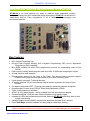
Photo 1—Although the Microchip PICDEM-3 development board was
module, which includes
designed years earlier, both the Atmel and Microchip boards contain simall of the necessary driver
ilar features. For instance, the boards come equipped with a 32-kHz
circuitry and LCD glass
external oscillator, a thermistor, several general-purpose push buttons,
in a compact package. If
and an external LCD port.
CIRCUIT CELLAR®
www.circuitcellar.com
the circuitry necessary to drive the
LCD glass. Fortunately, that technology is already walking the streets.
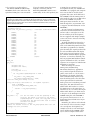
VLCD
VLCD
SEG1
SEG0
DRIVING MISS LCD
GND
GND
SEG1
SEG0
If you’ve worked with any of MicroVLCD
VLCD
COM0
chip’s PICs or Atmel’s AVRs, you’ve
COM0
already done the datasheet drill that
GND
GND
describes the core functionality of a PIC
V
LCD
and an AVR. Because the PIC16C923,
PIC16C924, PIC16C925, PIC16C926,
and ATmega169 are all about driving
GND
SEG1–COM0
SEG0–COM0
GND
LCD segments, it may be a good idea to
–VLCD
take a look at what it takes to make a
Frame
Frame
Frame
Frame
typical LCD work before I dive into
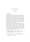
the specifics of what it takes to microFigure 2—The resultant voltage across a segment is the difference between the segment voltage and the common
controller-enable an LCD.
terminal voltage. Note that the sum of the voltages across the segment in each frame is equal to zero.
The term “LCD glass” refers to two
glass plates that contain and support a
layer of liquid crystal material. Liquid
When the liquid crystals are not
holding both of the polarized sunglass
crystals are rod-shaped molecules that
excited, they twist the light and allow
lenses back-to-back so you can see
flow as a liquid; they use their electriit to pass unimpeded through the outthrough them.
cal and optical properties to actually
of-phase polarizing filters. In the
If the liquid crystals become excited,
bend light. The inner surfaces of the
unexcited state, you see the normal
or energized, the molecules within the
glass plates are lined with transparent
background color of the LCD glass.
liquid crystals align themselves with
electrodes, which are patterned to
This unexcited state is relative to
the electric field and fail to twist the
form the images that are to be
light. In this case, the polarizers
displayed by the LCD. The
are out-of-phase and the light is
outer surfaces of the glass
not bent. Thus, the light cannot
V3
V2
plates are fitted with polarizers,
pass through the second polarizCOM3
BP0
V1
V0
which are placed perpendicular
er filter. This is analogous to
COM2
COM1
V3
to each other and parallel to
rotating one of the polarized
COM0
V2
BP1
V1
the liquid crystal rods.
sunglass lenses 90° and bringing
V0
The liquid crystal material
the lenses out of phase and
V3
has many layers of molecules.
blocking the light. The absence
V
2
BP2
V1
Each glass is rubbed with a
of light appears as a darkened
V0
polyimide coating that aligns
spot on the LCD glass.
V3
BP3
the liquid crystal material closUnlike standard LED disV2
V1
est to the glass with the polarplays, which are driven by
V0
izer. Because the polarizers are
applying a DC voltage across
SEG0
90° out of phase with each
each desired digit segment’s
V3
V2
other, the layers of liquid crystal
anode and cathode, LCD glass
V1
V0
material actually twist between
must be driven by an alternatV3
the upper and lower glass.
ing current. Each segment in an
V2
SEG1
V1
The best way I can explain
LCD connects to the driver on
V0
the polarizer/liquid crystal relaone side of the segment and to a
V3
tionship is to recall a childhood
common terminal on the other
V2
memory. Remember when the
side. Applying the AC across
V1
V0
BP0–SEG0
first polarized sunglasses came
the segment driver and the
–V1
–V2
out? No? Well, I do. If you
common terminal excites the
–V3
take the polarized lenses and
liquid crystal causing the segV3
look through them with one
ment’s liquid crystal molecules
V2
V1
to twist in such a way as to
lens behind the other, you
V0
BP0–SEG1
–V1
allow the segment to be visible.
can rotate one of the lenses
–V2
–V3
One frame
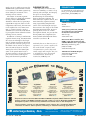
Even for a Cyclops, more
until the light is blocked and
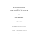
than one segment is needed to
you can’t see through the backFigure 3—This particular LCD glass contains four common terminals, which
make a programmable display.
to-back set of lenses. LCDs
implies four backplanes. Note that only a single segment driver is required
So, there has to be a process
work in a similar manner.
to drive up to four segments.
www.circuitcellar.com
CIRCUIT CELLAR®
Issue 159
October 2003
59
that determines which segments are
visible and at what time. On a typical
LCD, the LCD segments must be
excited more than 30 times per second
to keep you from seeing them flicker.
The number of times per second the
LCD segments are excited is called
the frame rate. LCD segments cannot
turn on or turn off instantaneously.
So, if the frame rate is too high, the
segments will appear to ghost,
because the segments aren’t given
enough time to turn off completely
before being excited again. The ghosting usually occurs when the frame
rate exceeds 100 frames per second.
The theory behind the LCD frame
rate is akin to video frames. Both use
the human eye and brain image persistence phenomenon to fool you into
seeing a bunch of really fast flickers as
smooth motion.
There are a couple of ways to drive
a collection of LCD segments. If all of
the LCD segments are tied to a single
common terminal with separate segment driver lines for each individual
segment, then you have a static
arrangement (see Figure 1).
Each segment must be driven above
its threshold voltage to excite the liq-
uid crystal molecules with the highest
voltage applied falling equal to or below
the maximum voltage specifications
set forth for the LCD glass segments.
Applying a DC voltage to an LCD segment will either end or shorten the life
of the segment, because the DC voltage
will eventually cause the liquid crystal
material to lose its excitability. For that
reason, the LCD driver waveforms are
designed to provide a potential across
the LCD segments that is as close as
possible to 0 VDC.
In a static segment arrangement,
square waves are normally used to
drive the common terminal and segments. Segments that are excited are
driven in opposite phase of the common terminal. If the segment and common drive signals are in phase, the segment is not excited. Figure 2 depicts
the segment and common terminal
drive signals and how they affect the
segments of a statically driven LCD.
A static LCD glass with one common terminal has only a one backplane and runs with a duty cycle of
1/1. Duty cycle is defined as one divided by the number of segments driven
by each LCD driver, or one divided by
the number of common terminals.
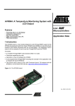
Figure 4—Although there appears to be a million pins on the headers and LCD glass, after laying out everything
on a spreadsheet the process of hooking up everything was simple.
60
Issue 159
October 2003
CIRCUIT CELLAR®
An example of LCD glass capable of
running at a one-fourth duty cycle is
shown in Figure 3. Each segment driver drives four segments, each of which
is driven by a separate backplane
(common terminal). To control each
segment from a single segment driver,
the segment driver must be able to
generate multiple voltage levels. The
number of voltage levels is associated
with the drive bias. Mathematically,
drive bias is one divided by the number of voltage levels minus one:
1
Number of voltage levels − 1
Therefore, the drive bias for the LCD
glass in Figure 3 would be 1/3, and the
drive bias for the LCD glass in Figure 1
would be 1/1.
You don’t have to guess about how
to set the duty and bias parameters.
The LCD recommended duty cycle
and drive bias settings are normally
called out in the LCD’s datasheet.
Some LCD datasheets also provide a
recommended frame rate.
DO THE TWIST
I love my job. In the process of
researching and writing this column, I
collected a bunch of goodies to play
with. I have a Microchip PICDEM-3
PIC16C9xxx development board, an
Atmel STK502 development module,
and an assortment of static and multiplexed LCD glass. The Microchip parts
aren’t flash memory-based, so I’ve got
to churn and burn when I develop
code for the Microchip LCD microcontroller. Thus, I pulled out my fancy
UV eraser and obtained a PIC16C9xx
68-pin PLCC programmer socket for
my PRO MATE II. I hate waiting for
UV parts to erase between spins. So,
to keep myself busy, I procured a couple of extra PIC16C924/CL and
PIC16C925/CL UV erasable devices.
I’m also fully covered on the Atmel
side. The ATmega169 is flash memorybased and can be programmed and
debugged using the latest version of
AVR Studio and JTAG ICE. If I don’t
run into trouble coding the AVR, I can
use the STK500 development board
that supports the STK502 to program
the ATmega169 firmware spins. I gathered my family of LCD development
www.circuitcellar.com
tools together to produce Photo 1.
The Atmel STK502 and Microchip
PICDEM-3 both come with their own
specialized LCD glass. You can actual-
ly buy the Atmel LCD glass from a
company in Norway, but the
Microchip PICDEM-3 LCD is not a
commercial, off-the-shelf product. Just
Listing 1—Each element in the character table is made up of three 3-bit values. The 3-bit values are
mapped into the segment matrix of each digit. The data doesn’t actually get to the microcontroller’s LCD
segment registers until all is well inside the LCD frame interrupt service routine. A detailed look at how the
segments map to the character table can be found in the VIMLCD.xls spreadsheet, which you may download from the Circuit Cellar ftp site.
!
"#$$%&'()
*
+,+-./0
+
+,++110
"
+,+-2#0
+,+-##0
2
+,++#.0
1
+,+-#20
.
+,+-/20
#
+,++1#0
/
+,+-//0
3
+,+-#/0
4
+,++//0
+,+-/"0
+,+-"20
+,+-/10
+,+-220
5
+,++220
6
+,++++
78
9$
$!
*
8
:8
$ 8
($ ''+!
*
($);<'';=5!
*
$ '$>5;$558
$) ';=58
$;?)
??((@ )
'A++8
('+8B$;5C5;$@=D8EE!
*
:EE'$?%&8
7
7
*
$ '"8( (
?$)
;<''650$ ()
$) '658
F(($?
( )
7
7
7
www.circuitcellar.com
CIRCUIT CELLAR®
as LCD glass is common to both
development boards, the STK502 and
PICDEM-3 are equipped with temperature sensors that are used by demo
programs that come with each board.
The STK502 holds the ATmega169 in
place with the same type of ZIF socket
used on the STK501 to hold the
Atmega128 microcontroller. A standard through-hole, 68-pin PLCC socket supports the PIC16C924/CL on the
PICDEM-3.
As you’d expect, both LCD microcontrollers are filled with demo code
and are ready to run right out of the
box. In addition, both development
kits are supplied with ample example
source code that is focused on driving
the LCD glass.
An LCD demultiplexer driven by a
separate PIC16C73 is an interesting
aside to the Microchip LCD board. The
extra PIC is programmed to demultiplex the LCD glass signals produced by
the on-board PIC16C924 and display
them using a special segment versus
the common terminal display program
that runs on a PC host. Basically, the
PC host program/PIC hardware demultiplexer combination tells you which
segments are energized on which LCD
backplane in real time.
After absorbing the various
ATmega169 and Microchip
PIC16C92x datasheets, application
notes, and development board user
guides, I was ready to “do the twist.”
Fortunately, the minds of both the
Atmel and Microchip LCD development board designers roll in the same
silicon gutter because both boards
make provisions for attaching external
LCD glass. The Atmel board uses a
ribbon cable and headers to connect
the ATmega169 to the LCD glass. So,
all I have to do is to remove the 34-pin
ribbon cable and I’ve got direct access
to the pins of the ATmega169 and the
STK502 LCD glass. The PICDEM-3
also provides direct access to its onboard LCD glass and PIC via a 34-pin
ribbon cable.
Normally, the shelves in the Florida
room have all of the necessary compilers to morph any development kit
example code into a real-world application. Although the STK502 source
says it can be compiled with either
Issue 159
October 2003
61
the ICCAVR C compiler or the IAR C
compiler, the former choked badly
when I tried to compile the raw
STK502 source code that is provided
with the Atmel development board.
After some investigation, I found
that one of the include files was missing from the source code package. The
PICDEM-3 files are PIC assembler and
would have to be ported to C for use
in either the Microchip or Custom
Computer Services PIC C compilers.
My preference of C over assembler in
this case is justified by the easy
manipulation of tables and 16-bit values made possible by functions built
into the C compiler packages.
The good news is that the suggested
code formats and compiler types used
by the LCD development kits don’t
matter, because I’ve decided to use
the best ideas from both of the LCD
development board source code
libraries to turn on some LCD segments of my own. I knew this project
was off to a good start when I opened
my flock of LCD glass. There were
five LCDs inside an antistatic bag
62
Issue 159
October 2003
with their pins punched into a piece
of Styrofoam. A thin layer of standard
foam covered all the LCDs to protect
their top glass surfaces. I removed the
LCDs from the bag and lifted the
foam layer to peek at the devices. As I
peeled away the foam, every device
turned on the segments to produce a
visible one. I was already successfully
turning on segments and I hadn’t even
taken the LCD glass out of the packing material yet!
BENDING LCD CODE
The first order of business is to gather the specifications of the LCD glass
and set up the LCD driver devices
accordingly. I have static and multiplexed parts made by Varitronix. The
static LCD is a VI-422-DP-RC-S and
the multiplexed display is identified as
VIM-404-DP-RC-S-HV. The “M” following the “VI” denotes that the LCD
is multiplexed, which implies multiple common terminals. Both displays
are instrument displays (VI) using
standard Twist Nematic, or TN, liquid-crystal fluid (S) with commercial
CIRCUIT CELLAR®
reflective polarizers (RC) in a dual inline package (DP). The “HV” parameter in the multiplexed display part
number specifies that the LCD is able
to operate at a higher typical operating
voltage than the static display.
The multiplexed VIM-404 has three
common terminals. Applying the duty
cycle formula gave me an LCD duty
cycle value of one-third. Because there
are three common terminals, you
know that each segment driver will
drive a maximum of three segments;
therefore, it will take four voltage levels to drive the three segments.
Applying the drive bias formula generates a resultant bias value of onethird. The Atmel and Microchip LCD
microcontrollers support my LCD’s
required duty cycle and drive bias. The
PIC16C924 drives up to 30 segments
with three backplanes, and the
ATmega169 drives up to 25 segments
on three backplanes. The VIM-404 has
a total of 33 segments. With each segment driver handling up to three segments, the VIM-404 uses only 12 segment drivers.
www.circuitcellar.com
Things are a bit different
are generated, both LCD
for the VI-422; it too has
driver microcontrollers ulti33 total segments. The
mately do the same job by
PIC16C924 can drive a maxiusing a similar internal
mum of only 32 segments
LCD data register setup.
Both microcontrollers have
with a single backplane, and
similar LCD register memothe ATmega169 is maxed out
ry maps. This similarity
at 25 segments, which simallows me to leverage the
ply means I cannot exploit
Atmel example code on the
the entire segment farm on
Microchip and Atmel develthe VI-422 with either LCD
opment boards. The Atmel
microcontroller. That’s not a
example code is easy to
showstopper. Regardless of
alter (it’s already in C forhow many segments I can or
Photo 2—Lots of information had to be assimilated to put numbers on the displays.
mat), so I adapted the existcannot drive, it takes 36 con- Although the schematic has enough graphical information to allow you to build the
display interfaces, a glance at the Excel spreadsheets exposes the logic behind it all.
ing Atmel example code to
nections to tie in all of the
drive a four-digit and an
segments of the statically
eight-digit LCD using the Microchip
driven VI-422 versus 15 connections
details the VIM-404 and VIM-808
PICDEM-3 electronics.
for the multiplexed VIM-404. The VIpinouts, the PIC16C924 segment
The Atmel C example code loads
422 is wired one segment to one LCD
memory layouts, the LCD character
an image of the segment buffer memdriver and doesn’t require a lot of
maps, the VIM segment-toory into an SRAM buffer and transthinking to implement. I’ll concenPIC16C924 segment driver combinafers the bit image from the SRAM to
trate on showing you how to impletions, and the initial LCD module
the actual segment memory during a
ment the VIM model.
register settings. You may download
frame interrupt. The frame interrupt
The connections from the developthe spreadsheet from the Circuit
occurs at the beginning of every
ment board to the external LCD glass
Cellar ftp site.
frame. There are flags within the
hardware are shown in Figure 4. I also
Despite some internal and external
frame interrupt service routine that
created an Excel spreadsheet that
differences in how the LCD voltages
www.circuitcellar.com
CIRCUIT CELLAR®
Issue 159
October 2003
63
CLEARING THE LCD
Although Photo 2 measures my
success in numbers, it’s time to stop
twisting code and light, and wrap up
this piece on driving LCDs.
Documenting the relationships
between the LCD segments, the
microcontroller segment drivers, and
microcontroller segment memory
using a spreadsheet amplified the
extent of the well-thought-out logic
that went into the design of the LCDs
and LCD microcontrollers. By incorporating ideas from a set of LCD
development boards, I’ve proven that
driving LCDs isn’t complicated, no
matter which embedded LCD microcontroller you choose. I
Fred Eady has more than 20 years of
experience as a systems engineer. He
has worked with computers and
communication systems large and
small, simple and complex. His forte
is embedded-systems design and
communications. Fred may be
reached at [email protected].
PROJECT FILES
To download the code and spreadsheet, go to ftp.circuitcellar.com/
pub/Circuit_Cellar/2003/159.
SOURCES
STK502 LCD Display
ACTE
www.acte.no
ATmega169, JTAG ICE, STK500
development board, and STK502
LCD demonstration board
Atmel Corp.
www.atmel.com
PIC16C924 Microcontroller, PICDEM-3 LCD demonstration board,
and PRO MATE II device programmer
Microchip Technology, Inc.
(480) 792-7200
www.microchip.com
VIM-404 and VIM-808 Displays
Varitronix International
(852) 2197-6000
www.varitronix.com
NEW
Products
μFlashTCP-EP *
10Base-T Ethernet
2 Serial Ports
7-34 VDC
Optional I/O Interface
Rugged Enclosure w/
Industry Standard
Connectors
Starts at $229
LogicFlex *
Dual-E *
10Base-T Ethernet
2 Serial Ports
46 Digital I /O’s
Programmable Xilinx CPLD
Hardware Clock/Calendar
Expansion Bus for
Peripheral Boards
Starts at $189
2 Ethernet Ports
2 Serial Ports
3 Counter / Timers
5 Digital I /O’s
Onboard Connectors
USNET TCP/IP
Software in Kits
Starts at $199
LogicFlex-EPX *
10Base-T Ethernet
2 Serial Ports
16 Opto-Isolated inputs
16 Relay Outputs @ 500mA ea.
Quick-Disconnect Connectors
Rack Mount Enclosure
LCD & 6 Pushbuttons
Starts at $499
*All products based on the Intel 386Ex with DOS and NE2000 compliant, 10Base-T Ethernet. Standard
memory includes 512K RAM & 512K Flash plus DIP socket to accept an M-Systems DiskOnChip.
Development systems contain necessary hardware and software tools for fast development.
TCP/IP Solutions
Tools to Move Data
can be set up to enable or prevent the
SRAM-based segment buffer contents
to be written to the LCD segment registers during the execution of the
interrupt service routine.
The nature of an LCD segment
doesn’t allow it to bend light instantaneously, and the VIM-404/808
datasheets reflect this by specifying a
typical 80-ms response time at room
temperature. Obviously, the LCD cannot be updated at every frame interrupt, so a timer routine is used to
determine how often the LCD actually gets updated from within the frame
interrupt service routine.
In addition to having a similar LCD
segment memory map, the PIC16C924
also issues an interrupt at the beginning of a frame. You know where I’m
going with this idea. I’m going to use
the Atmel code as well as its logic to
write the PIC code just as if I were
writing the code for the Atmel part.
Some of the ported Atmel code is
shown in Listing 1. I’ll post the entire
port on the Circuit Cellar ftp site
along with the Excel spreadsheet.
JK microsystems connects you with embedded control solutions. Our cost-effective DOS based
controllers are ideal for data acquisition, networking or industrial technology applications.
JK microsystems, Inc.
64
Issue 159
October 2003
1403 Fifth St., Suite D
Davis, CA 95616 USA
CIRCUIT CELLAR®
Visit us on the web www.jkmicro.com
Call 530-297-6073
Fax 530-297-6074
www.circuitcellar.com
HandsOn Technology
Low Cost 8051C Starter Kit/ Development Board HT-MC-02
HT-MC-02 is an ideal platform for small to medium scale embedded systems
development and quick 8051 embedded design prototyping. HT-MC-02 can be used as
stand-alone 8051C Flash programmer or as a development, prototyping and
educational platform
Main Features:
8051 Central Processing Unit.
On-chip Flash Program Memory with In-System Programming (ISP) and In Application
Programming (IAP) capability.
Boot ROM contains low level Flash programming routines for downloading code via the
RS232.
Flash memory reliably stores program code even after 10,000 erase and program cycles.
10-year minimum data retention.
Programmable security for the code in the Flash. The security feature protects against
software piracy and prevents the contents of the Flash from being read.
4 level priority interrupt & 7 interrupt sources.
32 general purpose I/O pins connected to 10pins header connectors for easy I/O pins
access.
Full-duplex enhanced UART – Framing error detection Automatic address recognition.
Programmable Counter Array (PCA) & Pulse Width Modulation (PWM).
Three 16-bits timer/event counters.
AC/DC (9~12V) power supply – easily available from wall socket power adapter.
On board stabilized +5Vdc for other external interface circuit power supply.
Included 8x LEDs and pushbuttons test board (free with HT-MC-02 while stock last) for fast
simple code testing.
Industrial popular window Keil C compiler and assembler included (Eval. version).
Free Flash Magic Windows software for easy program code down loading.
PLEASE READ HT-MC-02 GETTING STARTED MANUAL BEFORE OPERATE THIS BOARD
INSTALL ACROBAT READER (AcrobatReader705 Application) TO OPEN AND PRINT ALL DOCUMENTS
http://www.handsontec.com
HandsOn Technology is a manufacturer of high
quality educational and professional electronics
kits
and
modules,
uController
development/evaluation boards. Inside you will
find Electronic Kits and fully assembled and
tested Modules for all skill levels. Please check
back with us regularly as we will be adding many
new kits and products to the site in the near
future.
Do you want to stay up to date with electronics
and computer technology? Always looking for
useful hints, tips and interesting offers?
Inspiration and goals...
HandsOn Technology provides a multimedia and
interactive platform for everyone interested in
electronics. From beginner to diehard, from student to
lecturer... Information, education, inspiration and
entertainment. Analog and digital; practical and
theoretical; software and hardware...
HandsOn Technology provides Designs, ideas and
solutions for today's engineers and electronics
hobbyists.
Creativity for tomorrow's better living...
HandsOn Technology believes everyone should have the tools, hardware, and resources to play
with cool electronic gadgetry. HandsOn Technology's goal is to get our "hands On" current
technology and information and pass it on to you! We set out to make finding the parts and
information you need easier, more intuitive, and affordable so you can create your awesome
projects. By getting technology in your hands, we think everyone is better off
We here at HandsOn like to think that we exist in the same group as our customers >> curious
students, engineers, prototypers, and hobbyists who love to create and share. We are
snowboarders and rock-climbers, painters and musicians, engineers and writers - but we all have
one thing in common...we love electronics! We want to use electronics to make art projects,
gadgets, and robots. We live, eat, and breathe this stuff!!
If you have more questions, go ahead and poke around the website, or send an email to
[email protected]. And as always, feel free to let your geek shine - around here, we
encourage it...
http://www.handsontec.com