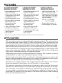
1
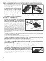
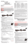
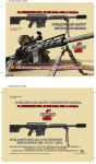
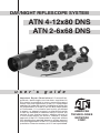
DAY/NIGHT RIFLESCOPE SYSTEM ATN 4-12x80 DNS ATN 2-6x68 DNS u s e r ` s g u i d e Impor tant Expor t Restrictions ! Commodities, products, technologies and services contained in this manual are subject to one or more of the export control laws and regulations of the U.S. Government and they fall under the control jurisdiction of either the US Department of State or the US BIS-Department of Commerce. It is unlawful and strictly prohibited to export, or attempt to export or otherwise transfer or sell any hardware or technical data or furnish any service to any foreign person, whether abroad or in the United States, for which a license or written approval of the U.S. Government is required, without first obtaining the required license or written approval from the Department of the U.S. Government having jurisdiction. Diversion contrary to U.S. law is prohibited. American Technologies Network Corp. 4-12x80 DNS DAY/NIGHT RIFLESCOPE SYSTEM DAYTIME SNIPER SCOPE Daytime eyepiece Eyepiece Adjustment Elevation Dust Cap Interchangeable cam Windage Dust Cap Lens 80mm, F1:1,4 Daytime eyepiece Magnification adjustment 10 position rheostat Battery housing Dust Cap NIGHT VISION WEAPON SIGHT IR Illuminator Digital Control 450 mw IR Illuminator Night Vision eyepiece battery Night Vision Eyepiece Power switch Night Vision Eyepiece Eyepiece Adjustment 2-6x68 DNS DAY/NIGHT RIFLESCOPE SYSTEM Cau ti o n : This product contains natural rubber latex which may cause allergic reactions. The information in this manual furnished for information use only, is subject to change without notice, is not to be construed as a commitment by ATN Corp. ATN Corp. assumes no responsibility or liability for any errors or inaccuracies that may appear in this book. ©2008 ATN Corp. All right reserved. FEATURES 412x80 DAYTIME SNIPER SCOPE 26x68 DAYTIME SNIPER SCOPE NIGHT VISION WEAPON SIGHT • Illuminated reticle with 10 position rheostat • 1000 -Yard Bullet drop compensator with interchangeable cams • 8 Interchangeable Cams • 40 mm tube for amazing light transmission • 40 mm adjustable mounting rings • 1000 Yard Range Finder • 1/8 MOA at 100 Yards • Proshield and Everlight Lens coatings • Sun shade • Illuminated reticle with 10 position rheostat • 50 0 -Yard Bullet drop compensator with interchangeable cams • 6 Interchangeable Cams • 42 mm tube for amazing light transmission • 42 mm adjustable mounting rings • 500 Yard Range Finder • 1/8 MOA at 100 Yards • Proshield and Everlight Lens coatings • Sun shade • Hight resolution Gen. 2+ Gen. 3 Intensifier Tube • Detachable 450 mW Infrared Illuminator with dedicated windage and elevation adjustment • FOV: 6°-2°(4-12x80) 10°-3°(2-6x68) • Diopter Adjustment: ± 5 • Power Supply: 3V lithium * ATN reserves the right to change the above specifications at any time without notice APPLICATION ATN is proud to present our unique day/night riflescope systems. This unit starts as a sensational daytime scopes. 80mm (!) objective and 40mm(!) tube combined with the best, German quality multi-coated glass on the market make this sight the best lightgathering device for shooting in the world. An array of features that will dazzle any marksmen includes parallax-free construction; 4 to 12 variable Power Zoom (2 to 6 for 2-6x68), 1000-Yard Bullet drop Compensator with interchangeable cams for eight calibers (500 yards and six calibers for 2-6x68) , 1000 Yard Range Finder (500 Yard for 2-6x68) and a super sharp, illuminated reticle with 10 brightness settings. Additional features include 1/8 MOA adjustment at 100 yards, 100% weather resistance and Matte Black mil-spec finish with beryllium powder coating. But wait it gets even better! With a simple twist of the eyepiece you can remove the daytime riflescope eyepiece and replace it with a Night Vision eyepiece converting your scope into a high quality, very accurate night vision weapon sight. The Night Vision eyepiece utilizes a Gen. 3 Light Intensifier Tube (same as used in Desert Storm and standard for Navy Seals). Also US 2nd Gen.+ IIT are available. This ingenious setup allows the shooter to go from day to night in less then 30 seconds without tools, without changes in eye relief and re-zeroing all around the clock. A separate, removable, most powerful in the industry (450mW) long-range Infrared Illuminator is also included to provide the user with total darkness capability. Furthermore the US government just granted ATN with a patent for the feature that prevents Tube from being burnt out by the illuminated reticle. 2 OPERATIONAL INSTRUCTION Mounting ATN adjustable rings have rotatable inserts which allow for as much as 20 Minutes of Angle, or approximately 20 inches at 100 yards, mounting adjustment without touching the scopes internal windage and elevation mechanisms. This in turn allows the user to maintain the scopes center of optical axis when performing the initial installation of a new ATN rifle scope. This feature is extremely important in eliminating parallax and maintaining a centered reticle with application of these units, while offering greater overall zero range selectivity. Each ATN scope is furnished with a set of non-offset rings usable with any Weaver or Picatinny style mount. These may also be reversed for more inter ring distance options or the recoil lug on the underside of each ring can be reversed (turned 180 degrees) by removing the two screws attaching it to the ring. Additionally, we offer an offset ring that when coupled with either standard or extended bases, will allow proper mounting on most any production or custom action. The rings provided with your scope have the correct height to allow for the necessary bell clearance required. INSTALLATION The Select the appropriate bases for your application. These can be 2 piece, one piece or rail. When installing the bases be sure and use Locktite or an equivalent thread locker on the mounting screws. Most bases install with 6-48 screws and these should be torqued to about 22 inch/lbs. Generally all receiver/base combinations have some degree of misalignment. However, this is not a problem with the ATN rings as this is easily compensated for by the floating ring inserts, assuring a stress free scope/mount/ receiver combination, another important accuracy consideration. Attach the rings to the bases and determine if you have the right distance center to center. The rings must not be closer than 1/8 inch to any place where the scope transitions from the 30 mm main tube including the turret area. Closer than 1/8 inch may cause turret or variable power adjustment binding. The available offset ring has 1 inch of distance form the center of the ring and used with or without extension base(s), if necessary, should easily cover all base mounting or eye relief problems. Tighten the ring securing side nuts finger tight. 3 Figure 1 Figure 2 Figure 3 Remove the tops of both rings and inserts and cradle the scope in their lower halves. Install the top halves and tighten each ring’s four screws to finger tight (Figure 1). Do not over tighten or you will be unable to rotate the offset inserts. The use of a bore sight or collimator at this stage is very helpful setting the initial alignment of scope and bore. This can also be accomplished by placing a well-lit and defined bull’seye target with at least a 6-inch black, 100 yards from a sand bagged and well supported rifle. Using the 100yard distance to target will give a convenient zero but other distances can be used. It will, however, require more adjustment during live fire to achieve a 100 yd. zero. Sighting thru the bore with the action open center the black bull’s-eye in your rifles bore. You would like the black circle of the bull’s-eye centered in the scopes field of view with the crosshair in the center of the bull. If it is not, first use the side nuts that secure the rings to the bases to adjust the scope to zero windage (Figure 2). Alternately loosening and tightening the side nuts while checking the bores alignment will move the scope crosshair accordingly: Looking from behind the scope in normal shooting position. Figure 4 Loosening the rear rings left side nut and then retightening the right side will move the crosshair to the left. Reversing this procedure will move the crosshair to the right. Adjustment using the front rings screws will result in the opposite. Loosening the front rings left side nut and tightening the right will move the crosshair to the right. Next check the elevation for zero. If the crosshair is not centered adjust it by rotating the a centric inserts via the following method: Use the slot milled into the top half of each ring to access the holes drilled thru the insert (Figure 3). Move the inserts radially to achieve the above described scope picture by inserting a round rod into the holes drilled in the insert (Figure 4). The shank (blunt end) of a 9/64 drill works perfectly. When the reticle is centered, tighten the ring screws exerting torque on the short end of the supplied allen wrench. It is not necessary to use the leverage of the long arm to tighten the screws any more than an additional 1/8 turn. 4 Sight in your rifle Chances are your rifle will not shoot to your bore sighted zero or to the zero you desire. This is primarily due to the rifles recoil impulse prior to the bullets departing the barrel. Recoil for RH twist barrels tends to carry the shot up and to the left. If you are more than 1 inch in any direction from the center of the bull or from your desired zero, adjust the scope using the rings insert mechanism or the rings side nuts as described above. It is always best to loosen the top halves of the ring just enough to allow free rotation or pivoting of the inserts so that stress is not introduced by any changes. Once you have zeroed your, windage retighten the side nuts and proceed to fine-tune the elevation. Both rings have 10 MOA adjustment via the insert. You will note that each insert has a thick and a thin side that allow a centric orientation of the scopes body in the rings. The scope’s elevation may be adjusted as follows: Placement of the thick side at 6 O’clock in the rear ring will result in raising the crosshair 10 inches at 100 yards. Conversely placing the thick side at 12 O’clock will lower it 10 inches. Again similar adjustments of the front ring’s insert will have an opposite effect; the thick side at 6 O’clock will lower the impact 10 inches at 100 yards. Therefore, placement of the thick side of the rear ring at 6 O’clock and the front’s at 12 O’clock will raise the impact a maximum of 20 inches at 100 yards. Any combination from 0 to 20 MOA is possible depending on the orientation of the inserts in tandem. NOTE: Any orientation of the inserts such that the thick sides of the inserts are not vertical, i.e., not at 12 or 6 O’clock, will result in a windage change in addition to elevation. In this case, once elevation has been achieved a final windage adjustment must be carried out using the side nuts as described above. Once your basic zero is set you can now use the scopes internal adjustments to fine tune impact to any shooting condition with the confidence that your optics are free of accuracy robbing parallax and stress. Focusing While holding the scope about four inches from your eye, quickly glance through the eyepiece at a featureless, flatly lit bright area such as a wall or the sky. CAUTION: Viewing the sun can cause serious eye injury, never look at the sun with this product or even the naked eye. If the reticle is not visible sharply turn the eyepiece (either direction) a few turns. Quickly glance through the scope again. If the focus has improved, but is still not perfect, continue focusing. If the focus condition became worse, turn it the opposite way. 5 ±5 Diopter Pre-zeroing Pre-zeroing is recommended and can be done with a scope guide or bore sight. These items have their own instructions. CAUTION: Be sure gun is not loaded. Use safe gun handling procedures all the time. Zeroing CAUTION: All shooting should be done at an approved range or other safe area. Eye and ear protection is recommended. DANGER If you are using a bore-obstructing device, remove it before proceeding. If the barrel hasbeen drilled for a mount, check that the screws do not protrude into the bore. Do not fire live or even blank ammunition with an obstructed barrel. An obstruction can cause serious damage to the gun and possible personal injury to yourself and others nearby. From a steady rest position, fire three rounds at a 100 yard target for 2-6x68 and 200 yard target for 4-12x80. Observe bullet strike on target and adjust windage and elevation screws as needed to correct aim. You will need to remove the dust caps from the top of the windage and elevation adjustments to do this. NOTE: Each click of adjustment changes bullet strike by the amount shown on the chart below. Windage / elevation (inches of movement per click) When you have finished zeroing, replace windage and elevation dust caps. 50 Yards-1/16” 100 Yards-1/8” 200 Yards-1/4” 300 Yards-3/8” Electronic Reticle Your scope has an Electronic reticle with 10 brightness positions. The rheostat is the knob located at the back of the scope. It is labelled with OFF and numbers 0-9. When the rheostat is set at 0 you will see a black etched reticle. The reticle will light up red electronically as you rotate the rheostat through the numbers, 9 being the brightest. 10 position rheostat for reticle brightness adjustment 6 ATn Rangefinder Reticle The rangefinder reticle in your riflescope was designed to assist you in determining the range of your target. These distances are based on a 6’ target, if a 6’ target fits between the numbered baseline (the five short horizontal lines) and the post of the reticle above the baseline determines your distance. If a 6’ target fits between the horizontal post of the reticle and 2 the target is 200 yards away. If the same target fits between the 4 and the horizontal post of the reticle the target is 400 yards away. The same is with the 6 and 10. The target would be either 600, 800 or 1000 yards away. If a 6’ target fits between these two lines then the target is 200 yards away. If a 6’ target fits between these two lines then the target is 400 yards away. MILDOT RETICLE Mil dot reticle is a reliable mean for determining distances to targets, introducing leads for moving targets, and for alternate aiming points for windage and elevation holds. Look through the scope, and bracket the object between dots. The space between dot centers subtends one milliradian (mil). One mil. subtends 3.6 inches at 100 yards or 36 inches at 1,000 yards. To use this system effectively you must know the size of the target. By measuring the height or width of a known (or approximately known target size) in milradians using the reticles, the target distance can be calculated as follows. R = range in meters, H = target size in meters, M = mil-radians of the image size: R = 1000 * H / M Military shooters are trained to know that the common male torso is 39 inches from crotch to top of head. This is very close to exactly one meter. This formula then becomes R = 1000 / M for a one meter target size. All of the following formula are equivalent to the one above for estimating range. R = range in meters, H = target size in inches, M = mil-radians of the image: R = 25.4 * H / M R = range in yards, H = target size in inches, M = mil-radians of the image: .1 mil .2 mil 1/4 mil 1/ 2 mil 3 /4 mil 1 mil R = 27.78 * H / M R = range in yards, H = target size in feet, M = mil-radians of the image: R=333.3 * H / M Bullet drop compensator The 4-12x also comes standard with a 1000 yard bullet drop compensator for the .50BMG round. The 2-6x also comes standard with a 500 yard bullet drop compensator for the .223 round. You should have zeroed your scope at 100 yards target for 2-6x68 and a 200 yard target for 4-12x80. When shooting at longer ranges the bullet drop compensator can be adjusted for 200, 300, 400, and 500 yards. Pending on the distance click the bullet 7 drop compensator to the appropriate setting. This will automatically adjust your reticle for that particular distance. Your 4-12x also comes with other cams allowing you to change your bullet drop compensator to work with the following categories: .308, 30-. 06, .270, 7 mm Mag, .300 Win Mag. 22-250, .243, .223. The 2-6x68 has the rounds for .223, .308, 30-.06, .270, 7mm MAG, .300 Win Mag. 200 yards compensation 500 yards compensation 200 yards 500 yards 1000 yards compensation 1000 yards Changing the Bullet Drop Compensator Set the bullet drop compensator to the 100-yards (2-6x68) or 200 yards (4-12x80) range. Then remove the elevation dust cover. Next you will find three small set screws on the bullet drop compensator right above the yardage numbers. Remove these screws and lift the cam off of the scope. Once you have done this select the desired caliber cam you would like to use and place this cam where you removed the previous one (make sure that a replacement cam is set to the 100-yard range for 2-6x68 and 200 yards for 4-12x80). Then tighten the cam by putting the three set screws back. Finally place the dust back. Maintaining your riflescope Your riflescope is waterproof and shockproof. However, you should never try to take apart or clean it internally (it will void your warranty). If your scope ever does need any repair or adjustment, it should be returned to ATN’s service department. The exposed optical surfaces will perform their best if they are wiped clean from time to time with a lens cloth or with optical quality lens paper like those for eyeglasses or camera lenses. Maintain the metal surfaces of your rifle scope by removing any dirt or sand with a soft brush so as to avoid scratching the finish. Wipe down the scope with a damp cloth and follow with a dry cloth. Finally, going over the tube with a silicone treated cloth will restore luster and protect the scope against corrosion. Be careful not to touch the lenses with the silicone cloth. The Night Vision Eyepiece The Night Vision eyepiece utilizes a US 2nd + or 3rd Gen. Light Intensifying Tube. A separate, removable, most powerful in the industry (450mW), long-range Infrared Illuminator is also included to provide the user with total darkness capability. Furthermore the U.S. government just granted ATN with a patent for the feature that prevents Tube from being burnt out by the illuminated reticle. 8 Replacing Day-Vision Eyepiece with Night-Vision One Release the detent along arrow “Open” on the sight body, turn it counter clockwise and take it out. In order to install the night-vision sight align the bayonet groove in the eyepiece body with the pin (or finger) on the interior surface of the sight body (its location is marked with a dot on the body), insert the eyepiece as far as it will go then turn it clockwise. Make sure that the detent has operated and the eyepiece won’t rotate or get out. Replace the night-vision with the day-vision one in a similar way. the IR Illuminator Infra-red (IR) Illuminators are common for IR Brightness Battery night vision technology. The IR light enhances Adjustment Housing greatly the performance of your day/night IR Elevation system (in night mode), while remaining almost invisible to a naked eye. In a dark enviBattery ronment, power up the day/night system (in Cap night mode) and observe a scene with the IR off. Then observe the same scene with the Fixation IR Focusing IR on. Note the difference in illumination. It is Screw IR Windage important to remember that the IR illuminator is an infra-red light source, and like any light source it may loose its effectiveness over a great distance. To fix the IR Illuminator to the riflescope screw the fixation screw on the IR into the thread on the night-vision eyepiece body. The IR illuminator control buttons are located on its side. To switch the Digital IR illuminator on/off press “+” and “-” buttons simultaneously. When the IR illuminator is switched on you can see the green LED lit. By pushing the buttons “+” and “-” you may adjust the IR brightness. The IR beam is focusable to change the field of coverage. To change the beam width slightly turn the IR lens. You may notice that beam of IR illuminator might not shine directly to the middle of your viewing image. You can change the direction of the IR beam slightly in horizontal and vertical directions with rotation of small screws on the side of IR. You can also change the position of the IR control panel fitting your needs. Unscrew the small set screw on back of IR. Then use the included wrench to loosen back ring, Move the IR to its desired position/angle, retighten ring with wrench then retighten set screw. 9 Preparing for Operation Day time Snip er S cop e : • Install the battery for illuminated reticle into its housing. • Adjust the magnification by rotating the magnification ring near eyepiece. • Observe the scene and adjust the eyepiece for optimal clarity. Get focus by rotating the focusing ring of the eyepiece. • Turn on the reticle illumination if you need. • Adjust the reticle brightness by rotating the 10-position rheostat. Night Vision Weapon Sight : • Install the batteries into their housing at night-vision eyepiece and IR illuminator respectively with the polarity order as shown at the device body. • Turn on the night-vision eye-piece with the switch located on its body. • Observe the scene and adjust the eyepiece for optimal clarity. Get focus by rotating the focusing ring of the eyepiece. • Turn on the IR illuminator . • Adjust IR brightness. • Focus the illuminator by rotating its lens. Batteries The batteries (included) are coin style 3 volt lithium batteries (CR2032) for Electronic Reticle and two 3 volt lithium batteries (CR123A) for Night Vision Eyepiece and IR Illuminator. VERY IMPORTANT! Your Day/ Night System comes with a patented technology that puts the lit reticle of the riflescope into an infrared mode which helps prevent the tube from being burnt out. However, even in this mode if the brightness of the reticle is turned up too high you can run the risk of burning the reticle pattern into your night vision light intensifier tube screen. This damage is not covered by the warranty! When setting the reticle brightness of your scope to Night Vision Mode please set the brightness at the lowest visible set ting comfor table for you. This will prolong the life of the Light Intensifier Tube. We suggest you to turn the reticle brightness to the (1) position and then increase it slowly until you see the reticle clearly. Do not over-increase the reticle brightness. 10 WARNINGS AND CAUTIONS • ALWAYS REMEMBER TO TURN OFF THE DAY/NIGHT RIFLESCOPE WHEN IT IS NOT IN USE. IF YOU DO NOT PLAN ON USING RIFLESCOPE FOR A PERIOD OF MORE THAN 10 DAYS, YOU SHOULD REMOVE THE BATTERIES. • Avoid touching lenses. If fingerprints or traces of dirt or dust appear, clean surface with photographic lens cleaning tissue. • Keep lens cap/daylight filter on when not in use. • Avoid contact with dust, steam, and gas. •THE DAY/NIGHT RIFLESCOPE is friendly to the user or environment. • Do not disassemble except to clean the front lens and the eyepiece: it will void your warranty. • Evaluate the scopes function by looking through it in a lit environment with the daylight filter lens cap on. Never use in daylight without the daylight filter lens cap on. Do not surpass ten minutes of testing. • Never point DAY/NIGHT RIFLESCOPE with night vision eyepiece at a bright light source. It the scope shuts off automatically after directing it at a bright light source, turn the unit off and wait for 1 - 2 minutes before turning the unit back on. • Adverse atmospheric conditions such as fog, smog, or haze and a lack of ambient light (moon or starlight) may diminish the effective viewing distance. All technical data for this unit was compiled in a controlled environment, therefore it may be difficult to recreate the conditions this scope was tested in. • If you use the rubber eyecaps for a long period of time, you may suffer skin inflammation. If you develop any symptoms, consult a doctor immediately. TROUBLESHOOTING Q: Flashes, flickers, or clicking occur while operating S: If it occurs within the first five minutes of inserting new batteries, it is normal and the device will resume normal operation soon thereafter. If it occurs for more than 10 minutes, contact your dealer or other authorized service representative for service instructions. Q: Dark spots on screen. S: These are cosmetic blemishes in the intensifier tube. They are a by-product of the process of manufacturing night vision tubes. They will not impede your viewing ability. Q: Image not clear. S: Adjust focus ring. If problem persists, increase viewing distance Q: Fixed-pattern noise in a honeycomb shape. S: Usually a cosmetic blemish characterized by a faint honeycomb-type pattern. This usually occurs when viewing very bright lights. Adjust the potentiometer, to reduce brightness. Q: A pattern of dark thin lines which look like chicken wire. 11 S: Turn on illuminator, if purchased. If illuminator doesn’t brighten image, replace batteries. If problem persists, contact ATN for service instructions. SPECIFICATION DAYTIME Magnification Objective diameter Mounting Rings Bullet drop calibers Field of Viev Eye Relief Rangefinding Illuminated reticle Power source Battery life Sun shade Recomended use* Adjustment windage and elevation Weight Dimensions NIGHT VISION Total Darkness Technology Intensifier Tube Field of View Diopter Adjustment Resolution Range of Focus Reticle Controls Power Supply Battery Life Dimensions Operating Temperatures Storage Temperature Weight 4-12x80 2-6x68 4-12x 80mm 40mm 50 BMG, .308, 30-.06, .270, 7 mm Mag, .300 Win Mag., 22- 250, .223, .243 2-6x 68 mm 42 mm .223, .308, 30-. 06, .270, 7 mm Mag, .300 Win Mag 6° - 2° 85 mm 1000 m/yard Yes 3-volt (CR2032) 100 hours Yes Ver 10° - 3° 80 mm 500 m/yard Yes 3-volt (CR2032) 100 hours Yes Tac, WFB 1/8 MOA at 100 m/yards 1.8 kg / 4.2 lbs 400 x 97 x 88 mm / 15” x 4” x 4” 1/8 MOA at 100 m/yards 1.45kg / 3.2 lbs 268 x 75 x 72 mm / 11” X 3” x 3” Standard 2nd or 3rd Gen. 6° - 2° ±5 Varies according to tube & Generation 20 m to infinity Green on green rangefinder Direct 3 volt (CR123A) 60 hours (Gen.2+); 50 hours (Gen.3 ) 442 x 125 x 88 mm / 17” x 5” x 4” -40°C to +50°C -50°C to +70°C 1.9kg / 4.3 lbs Standard 2nd or 3rd Gen. 10° - 3° ±4 Varies according to tube & Generation 20 m to infinity Green on green rangefinder Direct 3 volt (CR123A) 60 hours (Gen.2+); 50 hours (Gen.3 ) 325 x 100 x 75 mm / 13” x 4” x 3” -40°C to +50°C -50°C to +70°C 1.5kg / 3.3 lbs * Ver= Versatile, Tac=Law Enforcement, WFB= wide field brush country 12 2 Year product Warranty This product is guaranteed to be free from manufacturing defects in material and workmanship under normal use for a period of 2 (two) years from the date of purchase. In the event a defect that is covered by the foregoing warranty occurs during the applicable period stated above, ATN, at its option, will either repair or replace the product, and such action on the part of ATN shall be the full extent of ATN’s liability, and the Customer’s sole and exclusive remedy. This warranty does not cover a product (a) used in other than its normal and customary manner; (b) subjected to misuse; (c) subjected to alterations, modifications or repairs by the Customer of by any party other than ATN without prior written consent of ATN; (d) special order or “close-out” merchandise or merchandise sold “as-is” by either ATN or the ATN dealer; or (e) merchandise that has been discontinued by the manufacturer and either parts or replacement units are not available due to reasons beyond the control of ATN. ATN shall not be responsible for any defects or damage that in ATN’s opinion is a result from the mishandling, abuse, misuse, improper storage or improper operation, including use in conjunction with equipment which is electrically or mechanically incompatible with or of inferior quality to the product, as well as failure to maintain the environmental conditions specified by the manufacturer. CUSTOMER IS HEREBY NOTIFIED THAT OPERATION OF THE EQUIPMENT DURING DAYLIGHT HOURS OR UNDER ANY EXCESSIVE LIGHT CONDITIONS MAY PERMANENTLY DAMAGE THE INTERNAL COMPONENTS OF THE UNIT AND SAID DAMAGE WILL NOT BE COVERED UNDER THIS WARRANTY. This warranty is extended only to the original purchaser. Any breach of this warranty shall be waived unless the customer notifies ATN at the address noted below within the applicable warranty period. The customer understands and agrees that except for the foregoing warranty, no other warranties written or oral, statutory, expressed or implied, including any implied warranty of merchantability or fitness for a particular purpose, shall apply to the product. All such implied warranties are hereby and expressly disclaimed. Limitation of liability ATN will not be liable for any claims, actions, suits, proceedings, costs, expenses, damages or liabili- ties arising out of the use of this product. Operation and use of the product are the sole responsibility of the Customer. ATN’s sole undertaking is limited to providing the products and services outlined herein in accordance with the terms and conditions of this Agreement. The provision of products sold and services performed by ATN to the Customer shall not be interpreted, construed, or regarded, either expressly or implied, as being for the benefit of or creating any obligation toward any third party of legal entity outside ATN and the Customer; ATN’s obligations under this Agreement extend solely to the Customer. ATN’s liability hereunder for damages, regardless of the form or action, shall not exceed the fees or other charges paid to ATN by the customer or customer’s dealer. ATN shall not, in any event, be liable for special, indirect, incidental, or consequential damages, including, but not limited to, lost income, lost revenue, or lost profit, whether such damages were foreseeable or not at the time of purchase, and whether or not such damages arise out of a breach of warranty, a breach of agreement, negligence, strict liability or any other theory of liability. Product warranty registration 13 In order to validate the warranty on your product, ATN must receive a completed Product Warranty Registration Card for each unit or complete warranty registration on our website at www.atncorp.com. Please complete the included form and immediately mail it to our Service Center: ATN Corporation, 1341 San Mateo Avenue, South San Francisco, CA 94080. Obtaining warranty service 07032008 To obtain warranty service on your unit, End-user must notify ATN service department by calling 800-910-2862 or 650-989-5100 or via e-mail [email protected] to receive a Return Merchandise Authorization number (RMA). When returning please take or send the product, postage paid, with a copy of your sales receipt to our service center, ATN Corporation at the address noted above. All merchandise must be fully insured with the correct postage; ATN will not be responsible for improper postage or, missing or damaged merchandise during shipment. When sending product back, please clearly mark the RMA# on the outside of the shipping box. Please include a letter that indicates your RMA#, Name, Return Address, reason for service return, Contact information such as valid telephone numbers and/or e-mail address and proof of purchases that will help us to establish the valid start date of the warranty. Product merchandise returns that do not have an RMA listed may be refused or a significant delay in processing may occur. Estimated Warranty service time is 10-20 business days. End-user/customer is responsible for postage to ATN for warranty service. ATN will cover return postage/shipping after warranty repair to end-user/customer only if product is covered by aforementioned warranty. ATN will return product after warranty service by domestic UPS ground and/or domestic mail. Any other requested, required or international shipping method the postage/shipping fee will be the responsibility of the end-user/customer. 14 For customer service and technical support, please contact American Technologies Network Corp. North American Office 1341 San Mateo Avenue, South San Francisco, CA 94080 phone: 800-910-2862, 650-989-5100; fax: 650-875-0129 European Office phone: 44(0)870-0111286, fax: 44(0) 845-3349142 The following countries can use our toll free number 00 800 9102-8620 Austria, France, Germany, Holland, Italy, Spain, Sweden, Switzerland www.atncorp.com ©2008 ATN Corporation