1
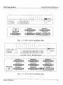
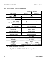
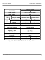
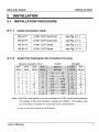
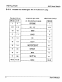
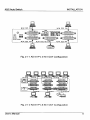
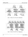
AS/2
AUTO SWITCH
AS-411P / AS-811P / AS-411S / AS-811S
User’s Manual
0 Copyright 1990 ATENB International CO., LTD.
Manual part NO. PAPE-0092-200
NOTICE
This manual is written for the Auto Switch products of AS-41 1 P/41 1 S and
AS-81 1P/811S. Most of the operations of these models are the some, and
differences will be specified. The last character ‘P’ and ‘S’ of each model’s string
means the parallel interface and the serial interface respectively.
In this manual, ‘AS/2’ is used to represent all the models of AS-41 1 P/
AS-41 1 S and AS-81 1 P/81 1 S. When you purchase this product it should contain
the following items.
PACKAGE CHECKLIST
l
An AS/P(any one of AS-41 1 P/AS-41 1 S/AS-81 1 P/AS-81 1 S)
l
The Power Adapter spec. depends on the following product model,
the power adapter supports AS-81 1 P model only.
Model
AS-411P 1
l
Spec.
NONE
-
An AS/2 Auto Switch User’s Manual
QUICK LOOK INTERFACE TABLE
MODEL
I
1
INPUT PORT
1 -- ~~~~
OUTPUT PORT
4 CENTRONICS Female
1
8 CENTRONICS Female
8 RS232C(DCE)
Female
POWER ADAPTER
SUPPORTED
1
BUFFER CARD
SUPPORTED
No/yes*
Yes
1 CENTRONICS Female
Yes
Yes
1 RS-232C(DTE) Male
NO
NO
1 RS-232C(DTE) Male
NO
NO
CENTRONICS Female
*The adapter comes with buffer card.
AS/2 is a trademark of ATEN International Co., Ltd. IBM PC, PC/XT and
PC/AT are trademarks of International Business Machines Corporation.
TABLE OF CONTENTS
FUNCTION OVERVIEW
l-l
Introduction .................................................................................... 1
l-2
Function Specifications ................................................................ 4
1-3 Product Limitation .......................................................................... 6
INSTALLATION
................................................................... 7
2-l
Installation Procedure
2-2
DIP Switch Setting
2-3
As Buffer Card Installation ............................................................ 13
....................................................................... 11
POWER ON PROCEDURE
3-l
Power On Procedure
................................................................. 15
3-2
Auto Switching Mode
.................................................................. 15
3-3
Manual Switching Mode ............................................................... 16
............................................................. 17
APPENDIX A
Trouble Shooting
APPENDIX B
Centronics Interface Timing Chart
APPENDIX C
Preventing Radio &TV Interference
................................. 18
.............................. 19
AS/2 Auto Switch
FUNCTION OVERVIEW
1 FUNCTION OVERVIEW
l-1 INTRODUCTION
The AS/2 is a high performance and low cost printer sharing device
which operates in either auto switching mode or manual switching mode. The
AS/2 allows up to four or eight source devices to share one common destination
devices. In the auto switching mode the AS/2 automatically locks on and
services the source device that requests to link with the common device.
However, in the manual switching mode the AS/2 works exactly the same way
as the conventional data switch.
There are four models, AS-41 1 P, AS-41 1S AS-81 1 P and AS-81 1 S all
belong to the AS/2 auto switch products. These differences can be quickly
understood by reading the following table.
AS-81 1 P
8 CENTRONICS Female
1 CENTRONICS Female
AS-41 1S
4 RS-232C(DCE) Female
1 RS232C(DTE) Male
AS-811s
8 RS-232C(DCE) Female
1 RS-232C(DTE) Male
The AS/2 tremendously improves the efficiency of your switching
applications. We suggest that you take a few moments to carefully read the
following instructions to ensure the maximum benefits and convenience your
AS/2 offers. The following figures are the AS/2's front views and rear views.
User’s Manual
1
FUNCTION OVERVIEW
AS/2 Auto Switch
1-2 FUNCTION SPECIFICATIONS
PARALLEL MODEL
FUNCTIONS
Power Supply
. . Cable Length
CONNECTOR INPUT
I
/
AS-41 1 P
AS-81 1 P
I
D C 9V, 100mA* / DC 9V, 100mA
I
I
(DB-25)Female OUTPUT
6M
4 CENTRONICS
8 CENTRONICS
1 CENTRONICS
1 CENTRONICS
Input Status
LED Printer Ready
Manual
4
8
1
1
1
1
Buffer Care (Extended)
256K/1 M/2M Bytes
Input Arbitration
First Come, First Serve
Function Key
Manual Select
Input Port Selection
Auto or Manual
Time out Selection
5 - 60 sec.
Auto From Feed
Enabled/Disabled
Ooeration Temp. 1
Dimensions
1224xl54x615mm /205x97x230mn
*The adaptor comes with buffer card.
Fig. 1-2-l AS-41 1 P/AS-81 1 P’s Function Specifications
4
User’s Manual
FUNCTION OVERVIEW
AS/2 Auto Switch
SERIAL MODEL
AS-81 1 s
AS-41 1 S
FUNCTIONS
Power Supply
AC 9V, 300mA (spare)
Cable Length
15M
CONNECTOR INPUT (Female) 4 RS-232C (DCE) 8 RS-232C (DCE)
(DB-25)
OUTPUT (Male) 1 RS-232C (DTE) 1 RS-232C (DTE)
1 Input Status
LED
I
Power
4
1
Manual
1
I
8
1
1
Input Arbitration
First Come, First Serve
Function Key
Manual Select
input Port Selection
Auto or Manual
Time out Selection
10-90 sec.
Operation Temp.
5°C - 40°C
Stock T e m p
-20°c - 60°c
I
Humidity
0% - 80%
I
Enclosure
Weight
Dimensions
Metal.
1850g
2520g
224 x 154 x 615mm 205 x 97 x 230mr
Fig. 1-2-l AS-41 1 S/AS-81 1 S’s Function Specifications
User’s Manual
5
FUNCTION OVERVIEW
AS/2 Auto Switch
1-3 PRODUCT LIMITATION
AS/2 is a well designed quality product. Its maximum performance and
limitation is described as follows.
l
AS/2's Auto Switching Mode is only suitable for devices which use
‘Hardware’ Handshaking, Xon-Xoflf Handshaking is not allowed.
l
AS/2's Manual Switching Mode is suitable for all kinds of Handshaking Modes.
l
For models of AS-41 1 P and AS-81 1 P, the cable length is limited to
no more than 6 meters.
l
, For models of AS-41 1 S and AS-81 1 S, the cable length is limited to
no more than 15 meters.
l
The Input Ports and the Output Ports are constantly configured to
be DTE or DCE that are shown in section l-2 Function Specifications. Make sure you are using the right cable to connect your PC
or devices to AS/2.
NOTE: DTE means Data Terminal Equipment.
DCE means Data Communications Equipment.
The Serial Interface and Parallel Interface mentioned in this manual
are RS-232C and Centronics respectively (please refer to Appendix
B).
AS/2 is IBM PC/AT/XT compatible.
6
User’s Manual
AS/2 Auto Switch
INSTALLATION
2-3 AS Buffer Card Installation
AS buffer card has 64K, 256K or 1M bytes of memory and is used to
expand the buffer memory of AS-41 1 P and AS-81 1 P auto switches.
1)
Unscrew the 4 screws on both sides of the case.
2)
Lift up the upper case.
3) Find the 14 x 2 gold pin connector on the PCB
for AS-41 1 P users: see Fig 2-3-l.
for AS-81 1 P users: see Fig 2-3-2.
4) Push the plastic spacers through the PCB to secure the AS Buffer Card
5) Place the upper case back and tighten the 4 screws back.
Fig 2-3-l The AS-41 1 P’s Buffer Card Installation
User’s Manual
13
INSTALLATION
AS/2 Auto Switch
Fig 2-3-2 The AS-81 1 P’s Buffer Card Installation
14
User’s Manual
AS/2 Auto Switch
POWER ON PROCEDURE
3 POWER ON PROCEDURE
3-1
POWER ON PROCEDURE
1) To reset the AS-81 1 P and AS-41 1 P (w/ buffer card), turn off/on power
switch. AS-41 1 P (w/o buffer card) can be reset by recycling printer
power while it is hooked to a printer.
2) After reset, the input channel’s service LEDs are on. Meanwhile, the
AS/2 is ready for operation and it enters the auto switching mode
automatically.
3-2 AUTO SWITCHING MODE
1)
In auto switching mode, all see the input channel’s service LEDs are
on. That means the AS/2 is standing by to get data from all channels.
2)
If any input channel requests to be served, the requested channel
LED will be on and the AS/2 will lock on to that channel. At this moment
the output port of AS/2 will’ only serve the locked input channel until
all the input data from the requested channel has been sent out and
also the time out period is up. The time out setting depends on the
current DIP Switch’s Setting of AS/2.
User’s Manual
15
POWER ON PROCEDURE
AS/2 Auto Switch
3) When the ‘READY’ LED turns off, it indicates
Connectors are not properly connected,
Printer(or output device) is not switched on,
Printer is not in ON-LINE status,
or, Printer is out of paper.
If buffer card installed for output ‘READY’ LED reflects buffer readiness.
4) When the AS/2 is serving a certain input channel, it does not switch to
serve another channel even though the printing gets interrupted by
printer’s power off or printer out of paper, etc.
NOTE:
Only in the Manual Switching Mode user can force the AS/2
to switch to and service another input channel.
3-3 MANUAL SWITCHING MODE
1)
Press the ‘SELECT’ button on the left side of the front panel to see the
corresponding LED comes on and the selected input channel’s LED
remains lit.
2)
Now, the AS/2 is in the Manual Switching Mode. If the manual
selected input channel stays on LED 1, then pressing the ‘SELECT’
button again the AS/2 will switch the input channel to the next channel
LED 2. Pressing the ‘SELECT’ button again, it will switch to the next
channel LED 3, and so on.
3) If the manual selected input channel stays on LED 4 (or LED 8), then
pressing the ‘SELECT’ button the AS/2 will enter Auto Switching Mode
and LED 1 - LED 4 (or LED 8) turned on.
16
User’s Manual
APPENDIX A
TROUBLE SHOOTING
PROBLEM
LED fails to light up
Failure of data
transmission
SOLUTIONS
Check if power is turned ON or not
1. Check if the Connector of each cable is well
plugged or not.
2. Check if PC is turned ON or not.
3. Check if PRINTER is turned ON or not.
4. Check if paper for PRINTER is well prepared
or not.
5. Check if Print command on PC is correct or
not.
6. Check if connector at computer’s end has
been connected in accordance with menu
Data Loss or Error
Check if the Handshake mode between the
$oo$;uter and AS/2 is the Hardware Handshake
If failure of printing still exists upon aforesaid solutions, please
contact your dealer for help.
User’s Manual
17
APPENDIX B
CENTRONICS INTERFACE TIMING CHART
Centronics Interface Timing Chart
I
DATA
,
I
I
I
1
I
-
ACK () -_____-___---______________
(min)
18
User’s Manual
APPENDIX C
PREVENTING RADIO&TV INTERFERENCE
Warning this equipment generates, uses and radiates radio frequency
energy and if not installed and used in accordance with the instruction manual
may cause interference to radio and television reception. It has been tested and
found to comply with the limits for a Class A computing device in accordance
with the specifications in Subpart J of Part 15 of FCC Rules, which are
designed to provide reasonable protection against such interference when
operated in a commercial environment. Operation of this equipment in a
residential area is likely to cause interference, in which case the user at
his own expense will be required to take whatever measures may be required
to correct the interference.
If this equipment does cause interference to radio or television reception,
which can be determined by turning the equipment off and on, the user is
encouraged to try to correct the interference by one or more of the following
measures:
1.
2.
3.
Reorient the reveiving antenna.
Relocate the computer with respect to the receiver.
Move the computer away from the receiver.
4.
Plu the computer into a different outlet so that computer and receiver
an8 on different branch circuits.
5.
Ensure that the mounting screws, attachment connector screws and
ground wires are tightly secured.
Ensure that good quality, shielded and grounded cables are used for
data communications
6.
If necessary, the user should consult the dealer or an experienced
radio/television technician for additional suggestions.
User’s Manual
19